EP1300569B1 - Verfahren und Vorrichtung zur Steuerung einer Brennkraftmaschine - Google Patents
Verfahren und Vorrichtung zur Steuerung einer Brennkraftmaschine Download PDFInfo
- Publication number
- EP1300569B1 EP1300569B1 EP02292416A EP02292416A EP1300569B1 EP 1300569 B1 EP1300569 B1 EP 1300569B1 EP 02292416 A EP02292416 A EP 02292416A EP 02292416 A EP02292416 A EP 02292416A EP 1300569 B1 EP1300569 B1 EP 1300569B1
- Authority
- EP
- European Patent Office
- Prior art keywords
- compression ratio
- engine
- pressure
- torque
- determined
- Prior art date
- Legal status (The legal status is an assumption and is not a legal conclusion. Google has not performed a legal analysis and makes no representation as to the accuracy of the status listed.)
- Expired - Lifetime
Links
Images
Classifications
-
- F—MECHANICAL ENGINEERING; LIGHTING; HEATING; WEAPONS; BLASTING
- F02—COMBUSTION ENGINES; HOT-GAS OR COMBUSTION-PRODUCT ENGINE PLANTS
- F02D—CONTROLLING COMBUSTION ENGINES
- F02D23/00—Controlling engines characterised by their being supercharged
- F02D23/02—Controlling engines characterised by their being supercharged the engines being of fuel-injection type
-
- F—MECHANICAL ENGINEERING; LIGHTING; HEATING; WEAPONS; BLASTING
- F02—COMBUSTION ENGINES; HOT-GAS OR COMBUSTION-PRODUCT ENGINE PLANTS
- F02D—CONTROLLING COMBUSTION ENGINES
- F02D13/00—Controlling the engine output power by varying inlet or exhaust valve operating characteristics, e.g. timing
- F02D13/02—Controlling the engine output power by varying inlet or exhaust valve operating characteristics, e.g. timing during engine operation
-
- Y—GENERAL TAGGING OF NEW TECHNOLOGICAL DEVELOPMENTS; GENERAL TAGGING OF CROSS-SECTIONAL TECHNOLOGIES SPANNING OVER SEVERAL SECTIONS OF THE IPC; TECHNICAL SUBJECTS COVERED BY FORMER USPC CROSS-REFERENCE ART COLLECTIONS [XRACs] AND DIGESTS
- Y02—TECHNOLOGIES OR APPLICATIONS FOR MITIGATION OR ADAPTATION AGAINST CLIMATE CHANGE
- Y02T—CLIMATE CHANGE MITIGATION TECHNOLOGIES RELATED TO TRANSPORTATION
- Y02T10/00—Road transport of goods or passengers
- Y02T10/10—Internal combustion engine [ICE] based vehicles
- Y02T10/12—Improving ICE efficiencies
Definitions
- the present invention relates to a method and a control device of an internal combustion engine, particular of a motor vehicle, making it possible to control the compression ratio of the engine.
- a combustion chamber using the four-stroke cycle (admission, compression, expansion and exhaust), it also defines a rate ⁇ Geo compression determined by the geometry of the chamber and the sliding piston stroke in this chamber.
- This rate ⁇ Geo is equal to the ratio between the maximum volume V Max of the combustion chamber (the piston being at the "bottom dead point") and the minimum volume v Min of this chamber (the piston being at the "top dead center”) .
- Geo geometric ⁇ rate equals the rate ⁇ m where the admission of gas into the combustion chamber is effected during the duration of the piston intake stroke, the piston moving from the top dead center to bottom dead center. Conversely, if the admission time of the gases is less than the duration of the piston intake stroke, a volume V m of gas lower than the maximum volume V Max is introduced into the chamber and the rate ⁇ m decreases to a value V m / V Min less than ⁇ Geo .
- a high compression ratio ⁇ m for example from 10 to 12 for a gasoline engine, improves the efficiency of the combustion of the gases while a low compression ratio ⁇ m reduces the emission of pollutants such as oxides of nitrogen during combustion. It is also known that at high load, that is to say when the cylinder delivers a high torque, a high compression ratio can cause an anticipated combustion of the gases and cause a knock of the engine.
- the compression ratio of an engine is usually set for performance and pollutant emissions from its cylinders are acceptable whatever the operating conditions of the motor, and in particular his torque or his diet. But such average compression ratio does not prevent the rattling of the engine at high load.
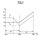
- Curve C 0 represents the pressure of the gases introduced into the chamber of a turbocharged engine not performing relaxation.
- the gas enters the chamber with a pressure P o fixed by the turbocharger and, when the gas inlet is stopped, the piston compresses these admitted gases to a maximum of pressure P e where combustion occurs.
- the turbocharger increases the pressure of the inlet gases to a pressure P 1 (curve C 1 ).
- the duration of the admission of the gases is decreased to perform the same filling, that is to say introduce the same amount of gas into the chamber as during the previously described admission (curve C o ).
- the piston is in the course of intake stroke.
- the admitted gases are thus expanded to a pressure P 2 during the end of the piston intake stroke which, during its compression stroke, compresses the gases to a pressure P e ', less than P e , where their combustion takes place.
- Such relaxation uses the cycle called the Miller cycle.
- the present invention relates to a method for to control the compression ratio of an engine internal combustion engine equipped with a turbocharger and valves controlled by electrical signals. It is characterized in that in real time a rate of optimal compression for engine operation, and controls the valves so that the admission of gases into the combustion chambers of the engine corresponds to this rate of optimal compression, torque and engine speed being kept independent of changes in the rate of compression thanks to a regulation of the gas pressure admitted and / or filling.
- This process makes it possible to adapt the compression ratio from an engine to its operation, for example in establishing a high compression ratio when the load the engine is weak or a low compression ratio when the load is high.
- the benefits of a rate of high compression (good combustion efficiency) and low compression ratio (particle emission reduced, limited risk of rattling) are then accessible to an engine using the process according to the invention.
- the rate of optimal compression according to at least one of following parameters: speed, torque and clatter of the motor.
- a gas inlet pressure adapted to the compression ratio optimal, at engine speed and torque to control the turbocharger.
- a database determining a first pressure of intake adapted to engine speed and torque in the case where a maximum compression ratio would be used, and the pressure adapted to the optimal rate is determined correcting the first pressure determined by a factor corrector determined by cartography.
- the filling is determined the engine according to the optimum compression ratio, engine speed, torque and / or the presence of rattling.
- valve opening time as a function of pressure gas intake, engine filling and fuel optimal compression.
- the compression ratio is decreased.
- the invention also relates to a device for control of an internal combustion engine equipped with electromagnetically controlled valves and a turbocharger, characterized in that it comprises means to determine an optimal compression ratio for the operation of the engine, means for controlling the valves so that the admission of gases into the combustion chambers of the engine corresponds to the rate of optimal compression, and pressure regulation and / or filling to maintain the torque and the speed of the motor independent of compression rate variations.
- the rate of optimal compression is a function of at least one of following parameters: speed, torque and clatter of the motor.
- a gas inlet pressure adapted to the compression ratio optimal, at engine speed and torque to control the turbocharger.
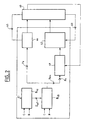
- the method of controlling the compression ratio of a engine described in Figure 2 applies to a cylinder 40 whose intake valves are controlled by an electromechanical actuator 42 (not shown in FIG. detail) which includes, for example, two electromagnets acting on a magnetic tray secured to a rod acting on another rod attached to the valve.
- an electromechanical actuator 42 which includes, for example, two electromagnets acting on a magnetic tray secured to a rod acting on another rod attached to the valve.
- the first electromagnet When the first electromagnet is activated, the rod integral with the valve is separated from the rod secured to the platter and the valve closes the cylinder under the action of a first spring acting on the valve stem.
- the second electromagnet is activated (the first one being rest) the rod secured to the magnetic plate pushes the valve stem so as to position it in opening.
- the activation signals of the electromagnets make it possible to change at will the moments of opening and closing, these moments being calculated as described later.
- the compression ratio of the cylinder 40 is adapted to the operation of the engine in varying the opening time of the intake valves, and therefore the gas filling admitted in the chambers of combustion. Moreover, when rattling is detected, the intake valves and the turbocharger are controlled 44 engine so as to eliminate this rattling by relaxing intake gases (Miller cycle).
- the implementation of the method uses a database B 46 determining the optimum compression rate ⁇ opt of the cylinder 40 as a function of its torque C, its R regime and the presence of clinking C1.
- the data of this database B 46 are obtained beforehand, for example by modeling or using a test bench, according to evaluation parameters such as the combustion efficiency, the emission of pollutants and / or the absence of rattling.
- a variation in the duration of opening of the intake valve changes the amount of gas introduced into the cylinder if the intake pressure is not suitable to compensate for this change.
- the duration of gas admission increases for increase the compression ratio of the engine, the pressure gas intake must decrease to the same amount fuel is introduced into the combustion chamber regardless of the variation of the compression ratio.
- a modification of the duration of opening of the valves would cause a variation unacceptable torque delivered by the engine without the knowledge of driver of the vehicle.
- the determination of the optimal compression ratio the adaptation of the gas inlet pressure to the rooms to compensate for the variation in the admission period gases and provide a torque C and a required R regime.
- a second database B 48 is used which determines the inlet pressure P a and the filling R em adapted to a given compression ratio ⁇ opt , the torque C and the R regime to be maintained.
- the filling is determined by taking into account only the filling R ' em necessary to obtain the torque C.
- f '( ⁇ opt ) is carried out by mapping considering the engine speed and torque as input variables, the mapping being established during engine-specific tests. considered.
- the pressure setpoint P a is transmitted to a turbocharger control module 44 for controlling the gas inlet pressure P a in the cylinder 40.
- This pressure is established by feedback 45 of the pressure measurement of overeating.
- the control of the turbocharger is a function of the difference between the pressure setpoint P a and the measured supply pressure.
- valve actuator 42 requires an intake pressure measurement for its operation.
- the actual pressure measurement has a dynamic that is too slow to satisfy the required accuracy. Therefore, a module 49 is used to estimate the boost pressure from measurements of the flow rate and the temperature of the air at the intake. A correction of this pressure estimate is made as a function of the setpoint pressure from module B 48 and the boost measurement.
- valve control filling control in real time, which makes it possible to compensate for problems of delay of evaluation of the pressure of admission gases.
- the device 42 determines the commands for opening and closing the intake valves for admitting the gas volume required in combustion chambers of the cylinder 40, at the determined pressure, so as to obtain the optimal compression ratio ⁇ opt .
- measurements 60 of the position of the intake valves are transmitted to the actuator 42.
- the invention is susceptible of many variants, for example by considering an engine comprising several cylinders that can be activated or deactivated.
- the valve control also takes into account, to obtain the given compression ratio, of these activations and / or deactivations.
Landscapes
- Engineering & Computer Science (AREA)
- Chemical & Material Sciences (AREA)
- Combustion & Propulsion (AREA)
- Mechanical Engineering (AREA)
- General Engineering & Computer Science (AREA)
- Output Control And Ontrol Of Special Type Engine (AREA)
- Supercharger (AREA)
Claims (10)
- Verfahren zur Regelung eines Motors mit interner Verbrennung, welcher mit durch elektrische Signale gesteuerten Ventilen und einem Turbokompressor (44) ausgerüstet ist, dadurch gekennzeichnet, dass ein für die Funktion des Motors optimaler Kompressionsgrad (τopt) in Echtzeit bestimmt wird, und die Ventile so gesteuert werden, dass das Laden von Gasen in die Verbrennungskammern des Motors diesem optimalen Kompressionsgrad entspricht, wobei das Moment (C) und die Drehzahl (R) des Motors dank einer Regelung des Drucks (Pa) der geladenen Gase und/oder der Füllung (Rem) unabhängig von Variationen des Kompressionsgrads gehalten werden.
- Verfahren nach Anspruch 1, dadurch gekennzeichnet, dass der optimale Kompressionsgrad (τopt) als Funktion wenigstens eines der folgenden Parameter bestimmt wird: die Drehzahl (R), das Moment (C) und das Klingeln (Cl) des Motors.
- Verfahren nach einem der Ansprüche 1 oder 2, dadurch gekennzeichnet, dass ein dem optimalen Kompressionsgrad (τopt), der Drehzahl (R) und dem Moment (C) des Motors angepasster Gasladedruck (Pa) zum Steuern des Turbokompressors (44) bestimmt wird.
- Verfahren nach Anspruch 3, dadurch gekennzeichnet, dass eine Datenbank (B48) verwendet wird, welche einen der Drehzahl (R) und dem Moment (C) des Motors für den Fall, dass ein maximaler Kompressionsgrad verwendet werden soll, angepassten ersten Ladedruck bestimmt, und der dem optimalen Grad (τopt) angepasste Druck bestimmt wird, indem der bestimmte erste Druck durch einen kartografisch bestimmten Korrekturfaktor korrigiert wird.
- Verfahren nach einem der vorhergehenden Ansprüche, dadurch gekennzeichnet, dass der Füllgrad des Motors als Funktion des optimalen Kompressionsgrads, der Motordrehzahl, seines Moments und/oder des Vorliegens von Klingeln bestimmt wird.
- Verfahren nach einem der vorhergehenden Ansprüche, dadurch gekennzeichnet, dass die Öffnungszeit der Ventile als Funktion des Gasladedrucks, der Füllung des Motors und des optimalen Kompressionsgrads bestimmt wird.
- Verfahren nach einem der vorhergehenden Ansprüche, dadurch gekennzeichnet, dass, wenn Klingeln erfasst ist, der Kompressionsgrad verringert wird.
- Vorrichtung zur Regelung eines Motors mit interner Verbrennung, welcher mit elektromagnetisch gesteuerten Ventilen und einem Turbokompressor ausgestattet ist, dadurch gekennzeichnet, dass sie Mittel zum Bestimmen eines für die Funktion des Motors optimalen Kompressionsgrads, Mittel zum Steuern der Ventile, derart, dass das Laden von Gasen in die Verbrennungskammern des Motors dem optimalen Kompressionsgrad entspricht, und eine Regelung des Drucks und/oder der Füllung um das Moment und die Drehzahl des Motors unabhängig von Variationen des Kompressionsgrads zu halten, umfasst
- Vorrichtung nach Anspruch 8, dadurch gekennzeichnet, dass der optimale Kompressionsgrad eine Funktion wenigstens eines der folgenden Parameter ist: die Drehzahl, das Moment und das Klingeln des Motors.
- Vorrichtung nach einem der Ansprüche 8 oder 9, dadurch gekennzeichnet, dass ein dem optimalen Kompressionsgrad, der Drehzahl und dem Motormoment angepasster Gasladedruck zum Regeln des Turbokompressors bestimmt wird.
Applications Claiming Priority (2)
| Application Number | Priority Date | Filing Date | Title |
|---|---|---|---|
| FR0112833 | 2001-10-05 | ||
| FR0112833A FR2830568B1 (fr) | 2001-10-05 | 2001-10-05 | Procede et dispositif de commande d'un moteur a combustion interne |
Publications (2)
| Publication Number | Publication Date |
|---|---|
| EP1300569A1 EP1300569A1 (de) | 2003-04-09 |
| EP1300569B1 true EP1300569B1 (de) | 2004-06-16 |
Family
ID=8867967
Family Applications (1)
| Application Number | Title | Priority Date | Filing Date |
|---|---|---|---|
| EP02292416A Expired - Lifetime EP1300569B1 (de) | 2001-10-05 | 2002-10-02 | Verfahren und Vorrichtung zur Steuerung einer Brennkraftmaschine |
Country Status (4)
| Country | Link |
|---|---|
| EP (1) | EP1300569B1 (de) |
| AT (1) | ATE269487T1 (de) |
| DE (1) | DE60200643T2 (de) |
| FR (1) | FR2830568B1 (de) |
Family Cites Families (3)
| Publication number | Priority date | Publication date | Assignee | Title |
|---|---|---|---|---|
| JP2662277B2 (ja) * | 1988-12-26 | 1997-10-08 | 本田技研工業株式会社 | エンジンの制御装置 |
| US5255637A (en) * | 1992-04-30 | 1993-10-26 | Ford Motor Company | Internal combustion engine with adaptive control of compression ratio |
| EP0945606A3 (de) * | 1998-03-27 | 2001-02-14 | Isuzu Ceramics Research Institute Co., Ltd. | Gasbrennkraftmaschine mit Turbolader und Motorgenerator |
-
2001
- 2001-10-05 FR FR0112833A patent/FR2830568B1/fr not_active Expired - Fee Related
-
2002
- 2002-10-02 DE DE60200643T patent/DE60200643T2/de not_active Expired - Lifetime
- 2002-10-02 AT AT02292416T patent/ATE269487T1/de not_active IP Right Cessation
- 2002-10-02 EP EP02292416A patent/EP1300569B1/de not_active Expired - Lifetime
Also Published As
| Publication number | Publication date |
|---|---|
| FR2830568B1 (fr) | 2004-01-23 |
| DE60200643T2 (de) | 2005-06-23 |
| DE60200643D1 (de) | 2004-07-22 |
| EP1300569A1 (de) | 2003-04-09 |
| FR2830568A1 (fr) | 2003-04-11 |
| ATE269487T1 (de) | 2004-07-15 |
Similar Documents
| Publication | Publication Date | Title |
|---|---|---|
| EP2925987A1 (de) | Verfahren zur steuerung einer doppelten suprageladenen brennkraftmaschine | |
| FR2884559A1 (fr) | Dispositif de commande d'un moteur a combustion interne | |
| FR2744173A1 (fr) | Procede permettant de commander un dispositif de recyclage des gaz d'echappement dans un moteur a combustion interne | |
| EP1300569B1 (de) | Verfahren und Vorrichtung zur Steuerung einer Brennkraftmaschine | |
| FR2758590A1 (fr) | Dispositif de commande d'un moteur a combustion interne a allumage commande et injection directe | |
| FR2761113A1 (fr) | Procede et systeme de regulation d'injection de carburant | |
| FR2916799A1 (fr) | Procede et dispositif de commande de soupape avec plusieurs phases de levee, procede d'alimentation d'un moteur | |
| FR3044359A1 (fr) | Procede de commande d'un moteur a combustion interne. | |
| EP2452060B1 (de) | Verfahren zur steuerung des in einen motor injizierten luftstroms, anordnung mit einem computer zur umsetzung des verfahrens und fahrzeug mit der anordnung | |
| FR2796421A1 (fr) | Procede de commande d'un moteur a combustion en vue de compenser la defaillance d'une soupape | |
| FR2835569A1 (fr) | Procede et dispositif de commande d'une unite d'entrainement comprenant un moteur a combustion interne | |
| FR2885389A1 (fr) | Procede de reduction des emissions d'hydrocarbures d'un moteur froid et dispositif et moteur mettant en oeuvre ce procede | |
| FR2947866A1 (fr) | Procede de controle d'un debit d'air injecte dans un moteur, ensemble comprenant un calculateur mettant en œuvre ce procede et vehicule comportant un tel ensemble | |
| EP1163437B1 (de) | Methode für das regeln der leerlaufdrehzahl einer verbrennungsmaschine mit ventilen ohne nockenwellen | |
| US20060243232A1 (en) | Plant control | |
| FR2868472A1 (fr) | Procede et dispositif de gestion d'un moteur a combustion interne | |
| FR2798963A1 (fr) | Procede de commande d'un moteur a combustion interne equipe d'un dispositif de recyclage des gaz d'echappement, et fonctionnant avec une charge stratifiee | |
| FR3149348A1 (fr) | Procédé de pilotage d’une pompe à air disposée dans un circuit d’air secondaire | |
| FR2851298A1 (fr) | Procede de commande d'un moteur thermique, appareil de commande et/ou de regulation pour un moteur thermique, programme d'ordinateur et support de memoire electrique d'un moteur thermique | |
| EP1601867A2 (de) | Verfahren zur steuerung eines motors mit eigenzündung mit homogener ladung | |
| FR2934643A1 (fr) | Procede de pilotage du phasage d'un arbre a cames d'un moteur en fonction de l'altitude | |
| FR2892459A3 (fr) | Moteur a combustion interne a taux de compression variable | |
| EP3475556B1 (de) | Verfahren zur bestimmung der zündvorverstellung eines verbrennungsmotors und verfahren zur steuerung eines motors mittels eines solchen verfahrens | |
| FR2870887A1 (fr) | Procede de gestion d'un moteur a combustion interne | |
| EP2044312A2 (de) | Verfahren zur reduktion von hc-emissionen aus einem kältemotor mit externer kraftstoffeinspritzung und motor zur ausführung dieses verfahrens |
Legal Events
| Date | Code | Title | Description |
|---|---|---|---|
| PUAI | Public reference made under article 153(3) epc to a published international application that has entered the european phase |
Free format text: ORIGINAL CODE: 0009012 |
|
| AK | Designated contracting states |
Kind code of ref document: A1 Designated state(s): AT BE BG CH CY CZ DE DK EE ES FI FR GB GR IE IT LI LU MC NL PT SE SK TR Designated state(s): AT BE BG CH CY CZ DE DK EE ES FI FR GB GR IE IT LI LU MC NL PT SE SK TR |
|
| AX | Request for extension of the european patent |
Extension state: AL LT LV MK RO SI |
|
| 17P | Request for examination filed |
Effective date: 20030919 |
|
| GRAP | Despatch of communication of intention to grant a patent |
Free format text: ORIGINAL CODE: EPIDOSNIGR1 |
|
| AKX | Designation fees paid |
Designated state(s): AT BE BG CH CY CZ DE DK EE ES FI FR GB GR IE IT LI LU MC NL PT SE SK TR |
|
| GRAS | Grant fee paid |
Free format text: ORIGINAL CODE: EPIDOSNIGR3 |
|
| GRAA | (expected) grant |
Free format text: ORIGINAL CODE: 0009210 |
|
| AK | Designated contracting states |
Kind code of ref document: B1 Designated state(s): AT BE BG CH CY CZ DE DK EE ES FI FR GB GR IE IT LI LU MC NL PT SE SK TR |
|
| PG25 | Lapsed in a contracting state [announced via postgrant information from national office to epo] |
Ref country code: AT Free format text: LAPSE BECAUSE OF FAILURE TO SUBMIT A TRANSLATION OF THE DESCRIPTION OR TO PAY THE FEE WITHIN THE PRESCRIBED TIME-LIMIT Effective date: 20040616 Ref country code: EE Free format text: LAPSE BECAUSE OF FAILURE TO SUBMIT A TRANSLATION OF THE DESCRIPTION OR TO PAY THE FEE WITHIN THE PRESCRIBED TIME-LIMIT Effective date: 20040616 Ref country code: TR Free format text: LAPSE BECAUSE OF FAILURE TO SUBMIT A TRANSLATION OF THE DESCRIPTION OR TO PAY THE FEE WITHIN THE PRESCRIBED TIME-LIMIT Effective date: 20040616 Ref country code: IE Free format text: LAPSE BECAUSE OF FAILURE TO SUBMIT A TRANSLATION OF THE DESCRIPTION OR TO PAY THE FEE WITHIN THE PRESCRIBED TIME-LIMIT Effective date: 20040616 Ref country code: CZ Free format text: LAPSE BECAUSE OF FAILURE TO SUBMIT A TRANSLATION OF THE DESCRIPTION OR TO PAY THE FEE WITHIN THE PRESCRIBED TIME-LIMIT Effective date: 20040616 Ref country code: SK Free format text: LAPSE BECAUSE OF FAILURE TO SUBMIT A TRANSLATION OF THE DESCRIPTION OR TO PAY THE FEE WITHIN THE PRESCRIBED TIME-LIMIT Effective date: 20040616 Ref country code: CY Free format text: LAPSE BECAUSE OF FAILURE TO SUBMIT A TRANSLATION OF THE DESCRIPTION OR TO PAY THE FEE WITHIN THE PRESCRIBED TIME-LIMIT Effective date: 20040616 Ref country code: BG Free format text: LAPSE BECAUSE OF FAILURE TO SUBMIT A TRANSLATION OF THE DESCRIPTION OR TO PAY THE FEE WITHIN THE PRESCRIBED TIME-LIMIT Effective date: 20040616 Ref country code: NL Free format text: LAPSE BECAUSE OF FAILURE TO SUBMIT A TRANSLATION OF THE DESCRIPTION OR TO PAY THE FEE WITHIN THE PRESCRIBED TIME-LIMIT Effective date: 20040616 Ref country code: FI Free format text: LAPSE BECAUSE OF FAILURE TO SUBMIT A TRANSLATION OF THE DESCRIPTION OR TO PAY THE FEE WITHIN THE PRESCRIBED TIME-LIMIT Effective date: 20040616 |
|
| REG | Reference to a national code |
Ref country code: GB Ref legal event code: FG4D Free format text: NOT ENGLISH |
|
| REG | Reference to a national code |
Ref country code: CH Ref legal event code: EP |
|
| REF | Corresponds to: |
Ref document number: 60200643 Country of ref document: DE Date of ref document: 20040722 Kind code of ref document: P |
|
| REG | Reference to a national code |
Ref country code: IE Ref legal event code: FG4D Free format text: FRENCH |
|
| GBT | Gb: translation of ep patent filed (gb section 77(6)(a)/1977) |
Effective date: 20040729 |
|
| PG25 | Lapsed in a contracting state [announced via postgrant information from national office to epo] |
Ref country code: SE Free format text: LAPSE BECAUSE OF FAILURE TO SUBMIT A TRANSLATION OF THE DESCRIPTION OR TO PAY THE FEE WITHIN THE PRESCRIBED TIME-LIMIT Effective date: 20040916 Ref country code: DK Free format text: LAPSE BECAUSE OF FAILURE TO SUBMIT A TRANSLATION OF THE DESCRIPTION OR TO PAY THE FEE WITHIN THE PRESCRIBED TIME-LIMIT Effective date: 20040916 Ref country code: GR Free format text: LAPSE BECAUSE OF FAILURE TO SUBMIT A TRANSLATION OF THE DESCRIPTION OR TO PAY THE FEE WITHIN THE PRESCRIBED TIME-LIMIT Effective date: 20040916 |
|
| PG25 | Lapsed in a contracting state [announced via postgrant information from national office to epo] |
Ref country code: ES Free format text: LAPSE BECAUSE OF FAILURE TO SUBMIT A TRANSLATION OF THE DESCRIPTION OR TO PAY THE FEE WITHIN THE PRESCRIBED TIME-LIMIT Effective date: 20040927 |
|
| PG25 | Lapsed in a contracting state [announced via postgrant information from national office to epo] |
Ref country code: LU Free format text: LAPSE BECAUSE OF NON-PAYMENT OF DUE FEES Effective date: 20041002 |
|
| PG25 | Lapsed in a contracting state [announced via postgrant information from national office to epo] |
Ref country code: MC Free format text: LAPSE BECAUSE OF NON-PAYMENT OF DUE FEES Effective date: 20041031 Ref country code: BE Free format text: LAPSE BECAUSE OF NON-PAYMENT OF DUE FEES Effective date: 20041031 |
|
| NLV1 | Nl: lapsed or annulled due to failure to fulfill the requirements of art. 29p and 29m of the patents act | ||
| REG | Reference to a national code |
Ref country code: IE Ref legal event code: FD4D |
|
| PLBE | No opposition filed within time limit |
Free format text: ORIGINAL CODE: 0009261 |
|
| STAA | Information on the status of an ep patent application or granted ep patent |
Free format text: STATUS: NO OPPOSITION FILED WITHIN TIME LIMIT |
|
| BERE | Be: lapsed |
Owner name: PEUGEOT CITROEN AUTOMOBILES SA Effective date: 20041031 |
|
| 26N | No opposition filed |
Effective date: 20050317 |
|
| PG25 | Lapsed in a contracting state [announced via postgrant information from national office to epo] |
Ref country code: CH Free format text: LAPSE BECAUSE OF NON-PAYMENT OF DUE FEES Effective date: 20061031 Ref country code: LI Free format text: LAPSE BECAUSE OF NON-PAYMENT OF DUE FEES Effective date: 20061031 |
|
| REG | Reference to a national code |
Ref country code: GB Ref legal event code: 746 Effective date: 20070119 |
|
| REG | Reference to a national code |
Ref country code: CH Ref legal event code: PL |
|
| BERE | Be: lapsed |
Owner name: S.A. *PEUGEOT CITROEN AUTOMOBILES Effective date: 20041031 |
|
| PG25 | Lapsed in a contracting state [announced via postgrant information from national office to epo] |
Ref country code: PT Free format text: LAPSE BECAUSE OF NON-PAYMENT OF DUE FEES Effective date: 20041116 |
|
| REG | Reference to a national code |
Ref country code: FR Ref legal event code: PLFP Year of fee payment: 15 |
|
| REG | Reference to a national code |
Ref country code: FR Ref legal event code: PLFP Year of fee payment: 16 |
|
| REG | Reference to a national code |
Ref country code: FR Ref legal event code: CA Effective date: 20180312 Ref country code: FR Ref legal event code: CD Owner name: PEUGEOT CITROEN AUTOMOBILES SA, FR Effective date: 20180312 |
|
| REG | Reference to a national code |
Ref country code: FR Ref legal event code: PLFP Year of fee payment: 17 |
|
| PGFP | Annual fee paid to national office [announced via postgrant information from national office to epo] |
Ref country code: FR Payment date: 20190919 Year of fee payment: 18 Ref country code: IT Payment date: 20190918 Year of fee payment: 18 |
|
| PGFP | Annual fee paid to national office [announced via postgrant information from national office to epo] |
Ref country code: GB Payment date: 20190923 Year of fee payment: 18 |
|
| PGFP | Annual fee paid to national office [announced via postgrant information from national office to epo] |
Ref country code: DE Payment date: 20190918 Year of fee payment: 18 |
|
| REG | Reference to a national code |
Ref country code: DE Ref legal event code: R119 Ref document number: 60200643 Country of ref document: DE |
|
| GBPC | Gb: european patent ceased through non-payment of renewal fee |
Effective date: 20201002 |
|
| PG25 | Lapsed in a contracting state [announced via postgrant information from national office to epo] |
Ref country code: FR Free format text: LAPSE BECAUSE OF NON-PAYMENT OF DUE FEES Effective date: 20201031 Ref country code: DE Free format text: LAPSE BECAUSE OF NON-PAYMENT OF DUE FEES Effective date: 20210501 |
|
| PG25 | Lapsed in a contracting state [announced via postgrant information from national office to epo] |
Ref country code: GB Free format text: LAPSE BECAUSE OF NON-PAYMENT OF DUE FEES Effective date: 20201002 |
|
| PG25 | Lapsed in a contracting state [announced via postgrant information from national office to epo] |
Ref country code: IT Free format text: LAPSE BECAUSE OF NON-PAYMENT OF DUE FEES Effective date: 20201002 |