EP1300593A2 - Vane compressor - Google Patents
Vane compressor Download PDFInfo
- Publication number
- EP1300593A2 EP1300593A2 EP02256837A EP02256837A EP1300593A2 EP 1300593 A2 EP1300593 A2 EP 1300593A2 EP 02256837 A EP02256837 A EP 02256837A EP 02256837 A EP02256837 A EP 02256837A EP 1300593 A2 EP1300593 A2 EP 1300593A2
- Authority
- EP
- European Patent Office
- Prior art keywords
- oil
- pressure chamber
- rotor shaft
- side block
- vane
- Prior art date
- Legal status (The legal status is an assumption and is not a legal conclusion. Google has not performed a legal analysis and makes no representation as to the accuracy of the status listed.)
- Withdrawn
Links
- 239000000314 lubricant Substances 0.000 claims abstract description 19
- 238000004891 communication Methods 0.000 claims description 3
- 238000007789 sealing Methods 0.000 abstract description 5
- 238000003754 machining Methods 0.000 description 10
- 239000003507 refrigerant Substances 0.000 description 10
- 230000002093 peripheral effect Effects 0.000 description 6
- 230000006835 compression Effects 0.000 description 5
- 238000007906 compression Methods 0.000 description 5
- 230000006866 deterioration Effects 0.000 description 4
- 238000010276 construction Methods 0.000 description 3
- 230000000694 effects Effects 0.000 description 2
- 230000033001 locomotion Effects 0.000 description 2
- 230000000717 retained effect Effects 0.000 description 2
- 239000004615 ingredient Substances 0.000 description 1
- 238000009434 installation Methods 0.000 description 1
- 238000000034 method Methods 0.000 description 1
- 238000000926 separation method Methods 0.000 description 1
- 230000003746 surface roughness Effects 0.000 description 1
Images




Classifications
-
- F—MECHANICAL ENGINEERING; LIGHTING; HEATING; WEAPONS; BLASTING
- F04—POSITIVE - DISPLACEMENT MACHINES FOR LIQUIDS; PUMPS FOR LIQUIDS OR ELASTIC FLUIDS
- F04C—ROTARY-PISTON, OR OSCILLATING-PISTON, POSITIVE-DISPLACEMENT MACHINES FOR LIQUIDS; ROTARY-PISTON, OR OSCILLATING-PISTON, POSITIVE-DISPLACEMENT PUMPS
- F04C29/00—Component parts, details or accessories of pumps or pumping installations, not provided for in groups F04C18/00 - F04C28/00
- F04C29/02—Lubrication; Lubricant separation
- F04C29/028—Means for improving or restricting lubricant flow
-
- F—MECHANICAL ENGINEERING; LIGHTING; HEATING; WEAPONS; BLASTING
- F01—MACHINES OR ENGINES IN GENERAL; ENGINE PLANTS IN GENERAL; STEAM ENGINES
- F01C—ROTARY-PISTON OR OSCILLATING-PISTON MACHINES OR ENGINES
- F01C21/00—Component parts, details or accessories not provided for in groups F01C1/00 - F01C20/00
- F01C21/08—Rotary pistons
- F01C21/0809—Construction of vanes or vane holders
- F01C21/0818—Vane tracking; control therefor
- F01C21/0854—Vane tracking; control therefor by fluid means
- F01C21/0872—Vane tracking; control therefor by fluid means the fluid being other than the working fluid
-
- F—MECHANICAL ENGINEERING; LIGHTING; HEATING; WEAPONS; BLASTING
- F01—MACHINES OR ENGINES IN GENERAL; ENGINE PLANTS IN GENERAL; STEAM ENGINES
- F01C—ROTARY-PISTON OR OSCILLATING-PISTON MACHINES OR ENGINES
- F01C21/00—Component parts, details or accessories not provided for in groups F01C1/00 - F01C20/00
- F01C21/10—Outer members for co-operation with rotary pistons; Casings
- F01C21/104—Stators; Members defining the outer boundaries of the working chamber
- F01C21/108—Stators; Members defining the outer boundaries of the working chamber with an axial surface, e.g. side plates
-
- F—MECHANICAL ENGINEERING; LIGHTING; HEATING; WEAPONS; BLASTING
- F04—POSITIVE - DISPLACEMENT MACHINES FOR LIQUIDS; PUMPS FOR LIQUIDS OR ELASTIC FLUIDS
- F04C—ROTARY-PISTON, OR OSCILLATING-PISTON, POSITIVE-DISPLACEMENT MACHINES FOR LIQUIDS; ROTARY-PISTON, OR OSCILLATING-PISTON, POSITIVE-DISPLACEMENT PUMPS
- F04C18/00—Rotary-piston pumps specially adapted for elastic fluids
- F04C18/30—Rotary-piston pumps specially adapted for elastic fluids having the characteristics covered by two or more of groups F04C18/02, F04C18/08, F04C18/22, F04C18/24, F04C18/48, or having the characteristics covered by one of these groups together with some other type of movement between co-operating members
- F04C18/34—Rotary-piston pumps specially adapted for elastic fluids having the characteristics covered by two or more of groups F04C18/02, F04C18/08, F04C18/22, F04C18/24, F04C18/48, or having the characteristics covered by one of these groups together with some other type of movement between co-operating members having the movement defined in group F04C18/08 or F04C18/22 and relative reciprocation between the co-operating members
- F04C18/344—Rotary-piston pumps specially adapted for elastic fluids having the characteristics covered by two or more of groups F04C18/02, F04C18/08, F04C18/22, F04C18/24, F04C18/48, or having the characteristics covered by one of these groups together with some other type of movement between co-operating members having the movement defined in group F04C18/08 or F04C18/22 and relative reciprocation between the co-operating members with vanes reciprocating with respect to the inner member
- F04C18/3446—Rotary-piston pumps specially adapted for elastic fluids having the characteristics covered by two or more of groups F04C18/02, F04C18/08, F04C18/22, F04C18/24, F04C18/48, or having the characteristics covered by one of these groups together with some other type of movement between co-operating members having the movement defined in group F04C18/08 or F04C18/22 and relative reciprocation between the co-operating members with vanes reciprocating with respect to the inner member the inner and outer member being in contact along more than one line or surface
-
- F—MECHANICAL ENGINEERING; LIGHTING; HEATING; WEAPONS; BLASTING
- F04—POSITIVE - DISPLACEMENT MACHINES FOR LIQUIDS; PUMPS FOR LIQUIDS OR ELASTIC FLUIDS
- F04C—ROTARY-PISTON, OR OSCILLATING-PISTON, POSITIVE-DISPLACEMENT MACHINES FOR LIQUIDS; ROTARY-PISTON, OR OSCILLATING-PISTON, POSITIVE-DISPLACEMENT PUMPS
- F04C2240/00—Components
- F04C2240/60—Shafts
-
- F—MECHANICAL ENGINEERING; LIGHTING; HEATING; WEAPONS; BLASTING
- F04—POSITIVE - DISPLACEMENT MACHINES FOR LIQUIDS; PUMPS FOR LIQUIDS OR ELASTIC FLUIDS
- F04C—ROTARY-PISTON, OR OSCILLATING-PISTON, POSITIVE-DISPLACEMENT MACHINES FOR LIQUIDS; ROTARY-PISTON, OR OSCILLATING-PISTON, POSITIVE-DISPLACEMENT PUMPS
- F04C29/00—Component parts, details or accessories of pumps or pumping installations, not provided for in groups F04C18/00 - F04C28/00
- F04C29/02—Lubrication; Lubricant separation
- F04C29/026—Lubricant separation
Definitions
- the present invention relates to a gas compressor used in a vehicle or the like as a part of an air conditioner.
- a vane type gas compressor for use in an air conditioner, a refrigerator or the like is known.
- the gas compressor will be described with reference to Fig. 4.
- a suction chamber 2 In one side portion of a casing 1, there is formed a suction chamber 2, and, adjacent to the suction chamber 2, there is provided a gas compressing portion.
- a tubular cylinder 3 In the gas compressing portion, there is provided a tubular cylinder 3 having an inner peripheral surface which is substantially elliptical in longitudinal section perpendicular to the axial direction, and a front side block 4 and a rear side block 5 fastened to the axial end surfaces thereof so as to be parallel to each other.
- a rotatable rotor 6 supported by a rotor shaft 10.
- this rotor 6 there are radially formed a plurality of (five in the example shown) vane grooves 7, and a vane 8 is slidably fitted into each vane groove 7 and retained therein.
- vane back pressure chambers 9 are formed so as to communicate with the grooves, and oil is supplied to the vane back pressure chamber 9 to aid the advancing and retreating motions of the vanes 8.
- a cyclone block 14 for separating oil component from compressed refrigerant gas, and a high pressure chamber 15 is formed on the rear side of the rear side block 5 and the cyclone block 14.
- the casing 1 has a discharge port (not shown) formed so as to communicate with the high pressure chamber 15, and at the bottom of the high pressure chamber 15, there is provided an oil sump portion 17.
- the refrigerant gas compressed in the cylinder 3 is discharged into the high pressure chamber 15 through the rear side block 5 and the cyclone block 14, and the high pressure refrigerant gas discharged into the high pressure chamber 15 is supplied to the exterior through the discharge port. Further, the oil obtained by separation through the cyclone block 14 falls onto the oil sump portion 17.
- the oil in the oil sump portion 17 is under the action of the discharge pressure of the high pressure refrigerant gas discharged into the high pressure chamber 15, and lubricant oil is supplied from the oil sump portion 17 through oil supply passages 20, 21, and 22 respectively formed in the cylinder 3, the front side block 4, and the rear side block 5 to the plain bearing portion of the rotor shaft 10 to lubricate the plain bearing portion. Further, a portion of the oil supplied to the plain bearing portions at the front and rear ends of the rotor shaft 10 is supplied to a small space 30 formed by the rear end surface of the rotor shaft 10 and the cyclone block 14 to prevent seizure of the rear end surface of the rotor shaft.
- the oil supplied to this small space 30 passes through the gap between the rear end surface of the rear side block 5 and the front end surface of the cyclone block 14, and, further, passes through an oil passage 23 formed in the rear side block 5 to be supplied to one flat groove 26 to supply the vane back pressure chamber 9 with oil.
- the small space 30 of the rear end surface portion of the rotor shaft is formed by the rear side block 6 and the cyclone block 14, so that to cut off the small space 30 from the discharge pressure space outside the cyclone block 14, an o-ring 31 is arranged for sealing between the rear side block 6 and the cyclone block 14 so as to surround the small space 30.
- the space of the rear end surface portion of the rotor shaft is filled with oil having a high temperature, and there exists gas or oil at high temperature and high pressure in the discharge pressure space outside the cyclone block, so that the O-ring is subject to deterioration due to heat, making it disadvantageously impossible to maintain an appropriate vane back pressure.
- the present invention has been made in view of the above problem. It is an object of the present invention to provide a compressor in which the need for installation of an O-ring around the small space is eliminated, thereby eliminating the problem due to the deterioration in the O-ring.
- a gas compressor comprising a tubular cylinder, a front side block and a rear side block situated at the axial ends of the cylinder, a rotor rotatably arranged in the cylinder, a vane groove provided in the rotor, a vane back pressure chamber provided so as to communicate with an inner peripheral-side end portion of the vane groove, a vane accommodated in the vane groove so as to be capable of advancing and retreating, a rotor shaft for rotating the rotor, a high pressure chamber into which compressed gas is discharged from the interior of the cylinder, and an oil sump portion in which oil is stored and to which the pressure of the high pressure chamber is applied, and is characterized in that there is provided a lubricant oil space inside the rear side block and on the side of the rear end surface of the rotor shaft, there being provided an oil supply passage for supplying oil from the oil sump portion to the lubricant oil space, and that there is
- the gas compressor is characterized in that there is formed in the front end surface of the rear side block a flat groove communicating with the vane back pressure chamber, and that the flat groove is connected to the oil passage to establish communication between the oil passage and the vane back pressure chamber.
- the gas compressor is characterized in that the vane back pressure chamber is formed in the rotor shaft along the axial direction, and that the oil passage is radially deflected on the cylinder side to communicate with the vane back pressure chamber, there being arranged in the oil passage a throttle valve for limiting the opening area of the oil passage by a force sucking oil toward the vane backpressure chamber generated in the oil passage.
- a small space is formed between the rear end portion of the rotor shaft and the rear side block, and the oil supplied to the small space is supplied to a vane back pressure chamber through an oil passage formed in the rear side block or the rotor shaft, so that it is possible to cut off the small space from the high pressure chamber without using any O-ring, making it possible to abolish the O-ring and supply oil to the vane back pressure chamber under an appropriate pressure .
- the above oil passage may be formed in the rear side block and connected as it is to the flat groove, etc. It is also possible to provide the oil passage so as to communicate with the small space and extend along the axial direction inside the rotor shaft, causing it to be once deflected toward the interior of the rear side block to be connected to the flat groove, etc.
- the centrifugal force acting in the oil passage portion extending along the radial direction increases as the RPM of the rotor shaft increases, and the force causing the oil in the oil passage move to the outer peripheral side, that is, the force sucking the oil toward the vane back pressure chamber is strongly applied to the oil in the rotor shaft, so that there is the danger of an excessive amount of oil being extracted from the lubricant oil space on the rotor shaft rear end portion side.
- Fig. 1 shows the general construction of a gas compressor.
- the gas compressor includes a casing 1 having at one end a suction port (not shown) and a discharge port (not shown). Connected to the suction port is a suction pipe (not shown) for sucking from outside the refrigerant gas to be compressed, and connected to the discharge port is a discharge pipe (not shown) for supplying the compressed refrigerant to a condenser or the like (not shown).
- a suction chamber 2 which communicates with the suction port.
- a tubular cylinder 3 having a substantially elliptical inner peripheral surface in longitudinal section perpendicular to the axial direction, a front side block 4 (suction port side) fastened to the axial end surfaces of the cylinder 3 so as to be parallel to each other, and a rear side block 5 (discharge port side).
- a rotatable rotor 6 supported by a rotor shaft 10, and this rotor 6 has a plurality of vane grooves 7 radially formed, a vane 8 being slidably fitted into each of them and retained therein. Further, a vane back pressure chamber 9 is formed so as to communicate with the inner peripheral-side end portion of each vane groove 7.
- the rotor shaft 10 is connected to an electromagnetic clutch 11, and the drive force of a vehicle engine is transmitted to the rotor shaft 10 through the electromagnetic clutch 11 to rotate the rotor 6, whereby the vanes 8 advance and retreat in the vane grooves 7 by their centrifugal force and the hydraulic pressure of the lubricant oil due to the back pressure chambers 9, rotating while being held in close contact with the inner peripheral wall of the cylinder 3. Due to the rotation of the rotor 6, the interior of the cylinder 3 is partitioned by the rotor 6 and the vanes 8 to form a compression chamber 3a.
- an opening (not shown) is provided on the front side block 4 side so as to communicate with the compression chamber 3a, and a discharge hole (not shown) is formed on the rear side block 5 side; the gas taken in the compression chamber 3a through the opening is compressed, and the compressed gas compressed in the compression chamber 3a is discharged into the high pressure chamber 15 through the discharge hole and a passage (not shown) formed in the rear side block 5.
- a cyclone block 141 is mounted to the rear end side of the rear side block 5, and, in this cyclone block 141, the oil ingredient is separated from the compressed gas.
- the high pressure chamber 15 is formed, and a discharge port is formed in the casing 1 so as to communicate with the high pressure chamber 15. Further, at the bottom of the high pressure chamber 15, the oil sump portion 17 is provided.
- an oil supply passage 20 for moving oil from the oil sump portion 17 is formed so as to be directed toward the shaft center at the rear end of the rotor shaft 10, so that oil can be supplied to the plain bearing portion at the rear end of the rotor shaft 10.
- the oil supply passage 20 communicates with an oil supply passage 21 formed in the cylinder 3 along the axial direction
- the oil supply passage 21 communicates with an oil supply passage 22 formed in the front side block 4.
- the oil supply passage 22 extends toward the front end of the rotor shaft 10, making it possible to supply oil to the plain bearing portion at the front end of the rotor shaft 10.
- flat grooves 25 and 26 are respectively formed in the rear end surface of the front side block 4 held in contact with the rotor shaft 10 and the front end surface of the rear side block 5; in the flat grooves 25 and 26, the oil supplied to the plain bearing portions of the rotor shaft 10 flows in, and oil is supplied to the vane back pressure chambers 9. Further, in the rear side block 5, a boss configuration is imparted to the rear end surface side of the rotor shaft 10 so that a small space 35 for lubricant oil may be formed, and a recess is provided in the inner surface thereof. That is, the small space 35 is formed inside the rear side block 5.
- a vane back pressure chamber oil passage 40 whose one end communicates with the small space 35 for lubricant oil is formed so as to extend obliquely and substantially along the axial direction; the other end of the vane back pressure passage 40 is connected to the flat groove 26 and communicates with the vane back pressure chambers 9.
- the refrigerant gas is sucked into the suction chamber 2, and sucked into the cylinder 3 through an opening (not shown).
- the refrigerant gas is successively compressed by the compression chamber 3a formed by the rotor 6 and the vanes 8 continuing to rotate.
- the compressed refrigerant gas is discharged from a discharge opening (not shown) formed in the cylinder 3 into a compressed gas passage (not shown) formed in the rear side block 5.
- the compressed gas discharged moves successively through the compressed gas passage, and oil is separated therefrom in the cyclone block 141 before it is discharged into the high pressure chamber 15.
- the compressed gas discharged into the high pressure chamber 15 is successively discharged from the high pressure chamber 15 to an external condenser or the like through the discharge port of casing 1. On the other hand, the separated oil drips into the oil sump portion 17.
- lubricant oil is supplied to the oil supply passage 20, and is supplied to the plain bearing portion at the rear end of the rotor shaft 10 to lubricate the plain bearing portion. Further, a part of the oil in the oil supply passage 20 diverts to the oil passage 21 of the cylinder 3, and is supplied to the plain bearing portion at the forward end of the rotor shaft 10 by way of the oil passage 22 of the front side block 4 to lubricate that plain bearing, too.
- the oil supplied to the plain bearing portions at the front and rear ends of the rotor shaft 10 is throttled when passing the plain bearing portions to undergo a reduction in pressure, and is then supplied to the vane back pressure chambers 9 through the pair of flat grooves 25 and 26 provided in the rotor side end surfaces of the front side block 4 and the rear side block 5 to aid the advancement and retreating of the vanes 8.
- the oil supplied to the plain bearing portion at the rear end of the rotor shaft partly moves forwards to be supplied to the flat groove 26 as described above, and partly moves backwards to be supplied to the small space 35 formed by the rear end surface of the rotor shaft 10 and the cyclone block 14 to prevent seizure of the rear end surface of the rotor shaft.
- the oil supplied to this small space 35 passes through the vane back pressure chamber oil passage 40 and is supplied to the flat groove 26 to supply oil to the vane back pressure chambers 9.
- the small space 35 for accommodating oil in the rotor shaft rear end surface is cut off from the high pressure chamber 15 due to the boss configuration of the rear side block 5, so that there is no need to effect cutting-off by an O-ring as in the prior art. Thus, no problem due to a deterioration of the O-ring is involved.
- a vane back pressure chamber oil passage allowing communication between the small space on the rotor shaft rear end surface side and the flat groove is formed in the rotor shaft.
- a boss configuration is imparted to the rear side block 5 at a position at the rear of the rear end surface of the rotor shaft 10, and a small space 36 is formed between the rear end surface of the rotor shaft 10 and the inner surface of the rear side block 5.
- a vane back pressure oil passage 41 extending along the axial direction, its one end being formed in the small space 36.
- the oil passage 41 is radially deflected immediately before the side end surface of the rotor 6, and extends to the outer periphery to be connected to the flat groove 26.
- gas is compressed, and compressed gas is discharged from the discharge port.
- the oil in the oil sump portion 17 is supplied to the plain bearing portion of the rotor shaft 10 as in Embodiment 1 to lubricate the plain bearing portion.
- a portion of the oil is supplied to the small space 36 on the rotor shaft rear end surface side to prevent seizure of the rear end surface of the rotor shaft 10.
- the oil supplied to the small space 36 moves within the rotor shaft 10 through the oil passage 41, and is radially deflected on the rotor 6 side to be supplied to the flat groove 26 to thereby supply oil to the vane back pressure chambers.
- the small space 36 on the rotor shaft rear end surface is cut off from the high pressure chamber 15 by the boss portion of the rear side block, so that there is no need to provide an O-ring, which means it is possible to prevent a problem due to a deterioration in the O-ring.
- the oil passage 41 is provided inside the rotor shaft 10, so that there is no need to secure a thick-walled portion for forming the passage on the rear side block 5 side, and the wall thickness, size, etc. of the boss portion are reduced, whereby the volume of the rear side block is reduced. As a result, it is possible to increase the volume of the high pressure chamber.
- a plain bearing is used in the bearing portion for the rotor shaft 10.
- a hole forming the plain bearing requires a finish-machining of higher accuracy than in the case of a bearing hole for a ball bearing or a needle bearing.
- accuracy refers, for example, to the out-of-roundness and cylindricity of the hole, the surface roughness of the inner surface thereof, etc.
- the disposal of the chips and shavings generated at the time of machining is an important issue.
- the bearing hole is a through-hole.
- the chips and shavings generated when finish-machining this through-hole can be easily discharged to the exterior of the hole.
- the chips and shavings have practically no influence on the finishing accuracy of the hole.
- this bearing hole is a blind hole.
- the chips and shavings generated at the time of finish-machining are not easily discharged from the hole, and it is impossible to achieve a high accuracy finishing by the same machining method as that for a through-hole.
- the hole of the oil passage 40 is formed by machining beforehand so that the chips and shavings generated when finish-machining the bearing hole can be discharged through the hole of the oil passage 40.
- holes are provided in the cutting tool and the grinding tool for finish-machining the bearing hole, and the chips and shavings are discharged through these holes.
- the second embodiment in which the oil passage is formed inside the rotor shaft, is improved.
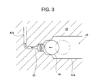
- the vane back pressure chamber oil passage 42 is formed at the axial center inside the rotor shaft 10 so as to extend along the axial direction, and is radially deflected toward the outer periphery on the rotor 6 side. That is, the oil passage is composed of an axial portion 42a and a radial portion 42b.
- the axial portion 42a is reduced stepwise in diameter as it extends toward the rotor side at the connection portion where it is connected to the radial portion 42b; at the connection portion, there is arranged in the radial portion 42b a coil spring 45 so as to extend backwards along the axial direction, and a spherical valve body 46 is fixed to the rear end portion thereof.
- this valve body 46 is situated in the large diameter portion of the axial portion 42a to secure a large opening area in the axial portion 42a.
- the valve body moves to the small diameter side of the axial portion 42a to diminish the opening of the axial portion 42a.
- the construction of this embodiment is the same as that of the second embodiment, and a description thereof will be omitted.
- the present invention provides a gas compressor comprising, a tubular cylinder, a front side block and a rear side block situated at the axial ends of the cylinder, a rotor rotatably arranged in the cylinder; a vane groove provided in the rotor, a vane back pressure chamber provided so as to communicate with an inner peripheral-side end portion of the vane groove, a vane accommodated in the vane groove so as to be capable of advancing and retreating, a rotor shaft for rotating the rotor, a high pressure chamber into which compressed gas is discharged from the interior of the cylinder; and an oil sump portion in which oil is stored and to which the pressure of the high pressure chamber is applied, wherein there is provided a lubricant oil space inside the rear side block and on the side of the rear end surface of the rotor shaft, there being provided an oil supply passage for supplying oil from the oil sump portion to the lubricant oil space, and that there is formed in the rear side block or in the rotor shaft
Landscapes
- Engineering & Computer Science (AREA)
- Mechanical Engineering (AREA)
- General Engineering & Computer Science (AREA)
- Rotary Pumps (AREA)
- Applications Or Details Of Rotary Compressors (AREA)
Abstract
Description
Claims (3)
- A gas compressor comprising:a cylinder;a front side block and a rear side block situated at the axial ends of the cylinder;a rotor rotatably arranged in the cylinder;a vane groove provided in the rotor;a vane back pressure chamber provided to an inner peripheral-side of the vane groove;a vane accommodated in the vane groove so as to be capable of advancing and retreating;a rotor shaft for rotating the rotor;a high pressure chamber into which compressed gas is discharged from the cylinder;an oil sump portion in which oil is stored and to which the pressure of the high pressure chamber is applied;a lubricant oil space arranged inside the rear side block and on the side of the rear end surface of the rotor shaft;an oil supply passage for supplying oil from the oil sump portion to the lubricant oil space; andan oil passage formed in the rear side block or in the rotor shaft, one end of the oil passage communicating with the lubricant oil space and the other end communicating with the vane back pressure chamber.
- A gas compressor according to Claim 1, wherein there is formed in the front end surface of the rear side block a flat groove communicating with the vane back pressure chamber, and that the flat groove is connected to the oil passage to establish communication between the oil passage and the vane back pressure chamber.
- A gas compressor according to Claim 1, wherein the vane back pressure chamber is formed in the rotor shaft along the axial direction, and that the oil passage is radially deflected on the cylinder side to communicate with the vane back pressure chamber, there being arranged in the oil passage a throttle valve for limiting the opening area of the oil passage by a force sucking oil toward the vane back pressure chamber generated in the oil passage.
Applications Claiming Priority (2)
| Application Number | Priority Date | Filing Date | Title |
|---|---|---|---|
| JP2001307281 | 2001-10-03 | ||
| JP2001307281A JP2003113787A (en) | 2001-10-03 | 2001-10-03 | Gas compressor |
Publications (2)
| Publication Number | Publication Date |
|---|---|
| EP1300593A2 true EP1300593A2 (en) | 2003-04-09 |
| EP1300593A3 EP1300593A3 (en) | 2003-04-16 |
Family
ID=19126771
Family Applications (1)
| Application Number | Title | Priority Date | Filing Date |
|---|---|---|---|
| EP02256837A Withdrawn EP1300593A3 (en) | 2001-10-03 | 2002-10-01 | Vane compressor |
Country Status (4)
| Country | Link |
|---|---|
| US (1) | US20030063991A1 (en) |
| EP (1) | EP1300593A3 (en) |
| JP (1) | JP2003113787A (en) |
| CN (1) | CN1409013A (en) |
Cited By (1)
| Publication number | Priority date | Publication date | Assignee | Title |
|---|---|---|---|---|
| DE102016211913A1 (en) * | 2016-06-30 | 2018-01-18 | Schwäbische Hüttenwerke Automotive GmbH | Vane pump with pressurizable underwing area |
Families Citing this family (11)
| Publication number | Priority date | Publication date | Assignee | Title |
|---|---|---|---|---|
| AU2004247229B2 (en) * | 2003-06-09 | 2006-12-14 | Saint-Gobain Ceramics & Plastics, Inc. | Fused zirconia-based solid oxide fuel cell |
| US9185538B2 (en) * | 2005-05-31 | 2015-11-10 | Qualcomm Incorporated | Wireless subscriber application and content distribution and differentiated pricing |
| DE102012103888A1 (en) * | 2012-05-03 | 2013-11-21 | Zf Lenksysteme Gmbh | Displacement pump for conveying of pressurizing agent to consumer, particularly vane-type or roller pump for transmission of motor vehicle, has pump packet with rotor, cam ring and multiple working slides |
| JP5949386B2 (en) * | 2012-09-24 | 2016-07-06 | 株式会社豊田自動織機 | Vane type compressor |
| JP6171482B2 (en) * | 2013-03-28 | 2017-08-02 | 株式会社豊田自動織機 | Vane type compressor |
| WO2015104930A1 (en) * | 2014-01-09 | 2015-07-16 | カルソニックカンセイ株式会社 | Gas compressor |
| ES2612232T3 (en) * | 2014-06-05 | 2017-05-12 | Wabco Europe Bvba | Vacuum pump and system of a vacuum pump and an engine |
| JP6350294B2 (en) * | 2015-01-15 | 2018-07-04 | 株式会社デンソー | Fuel pump |
| CN106481555B (en) * | 2015-08-25 | 2018-09-07 | 珠海格力节能环保制冷技术研究中心有限公司 | A kind of horizontal compressor and temperature equipment |
| KR102180179B1 (en) * | 2018-11-09 | 2020-11-18 | 엘지전자 주식회사 | Vain rotary compressor |
| CN113978206B (en) * | 2021-11-15 | 2023-07-21 | 常州康普瑞汽车空调有限公司 | Front cyclone blade type automobile air conditioner compressor |
Family Cites Families (6)
| Publication number | Priority date | Publication date | Assignee | Title |
|---|---|---|---|---|
| JPS609436Y2 (en) * | 1976-05-15 | 1985-04-03 | 株式会社ボッシュオートモーティブ システム | Movable vane rotary compressor |
| JPS5874890A (en) * | 1981-10-30 | 1983-05-06 | Hitachi Ltd | Rotary vane compressor |
| US4507065A (en) * | 1982-05-13 | 1985-03-26 | Diesel Kiki Co., Ltd. | Vane compressor having drive shaft journalled by roller bearings |
| JPS60132086A (en) * | 1983-12-19 | 1985-07-13 | Toyoda Autom Loom Works Ltd | Sliding vane compressor |
| JPS60192891A (en) * | 1984-03-14 | 1985-10-01 | Hitachi Ltd | vane compressor |
| JP2840818B2 (en) * | 1995-08-31 | 1998-12-24 | セイコー精機株式会社 | Gas compressor |
-
2001
- 2001-10-03 JP JP2001307281A patent/JP2003113787A/en active Pending
-
2002
- 2002-09-30 US US10/261,635 patent/US20030063991A1/en not_active Abandoned
- 2002-10-01 EP EP02256837A patent/EP1300593A3/en not_active Withdrawn
- 2002-10-03 CN CN02152917A patent/CN1409013A/en active Pending
Cited By (1)
| Publication number | Priority date | Publication date | Assignee | Title |
|---|---|---|---|---|
| DE102016211913A1 (en) * | 2016-06-30 | 2018-01-18 | Schwäbische Hüttenwerke Automotive GmbH | Vane pump with pressurizable underwing area |
Also Published As
| Publication number | Publication date |
|---|---|
| JP2003113787A (en) | 2003-04-18 |
| CN1409013A (en) | 2003-04-09 |
| EP1300593A3 (en) | 2003-04-16 |
| US20030063991A1 (en) | 2003-04-03 |
Similar Documents
| Publication | Publication Date | Title |
|---|---|---|
| KR101290005B1 (en) | Scroll compressor | |
| EP1300593A2 (en) | Vane compressor | |
| MXPA01001177A (en) | Scroll compressor. | |
| JP2005256684A (en) | Vane pump for gas and operation method thereof | |
| CN111247343A (en) | Lubricant supply channel for compressor | |
| US5823755A (en) | Rotary compressor with discharge chamber pressure relief groove | |
| US4484868A (en) | Vane compressor having improved cooling and lubrication of drive shaft-seal means and bearings | |
| JP5707337B2 (en) | Lubricating oil supply structure for vane compressor | |
| EP0683321A1 (en) | Swinging rotary compressor | |
| US4104010A (en) | Rotary compressor comprising improved rotor lubrication system | |
| JP4806262B2 (en) | Compressor | |
| US9556872B2 (en) | Gas compressor formed with a high-pressure supply hole | |
| US4086041A (en) | Rotary compressor comprising improved rotor lubrication system | |
| US4408969A (en) | Vane compressor having improved rotor supporting means | |
| CN102966543A (en) | Vane-type compressor | |
| US11668308B2 (en) | Compressor having sliding portion provided with oil retainer | |
| JPH11247761A (en) | Hermetic compressor | |
| JP3616056B2 (en) | Rotary compressor | |
| JP2004190510A (en) | Gas compressor | |
| JP4436185B2 (en) | Compressor | |
| JPH10252674A (en) | Gas compressor | |
| JP2004190509A (en) | Gas compressor | |
| US11674514B2 (en) | Compressor with a fitted shaft portion having two sliding surfaces and an oil retainer | |
| JP2008008259A (en) | Gas compressor | |
| EP2857688B1 (en) | Rotary compressor |
Legal Events
| Date | Code | Title | Description |
|---|---|---|---|
| PUAI | Public reference made under article 153(3) epc to a published international application that has entered the european phase |
Free format text: ORIGINAL CODE: 0009012 |
|
| PUAL | Search report despatched |
Free format text: ORIGINAL CODE: 0009013 |
|
| AK | Designated contracting states |
Kind code of ref document: A2 Designated state(s): AT BE BG CH CY CZ DE DK EE ES FI FR GB GR IE IT LI LU MC NL PT SE SK TR Designated state(s): AT BE BG CH CY CZ DE DK EE ES FI FR GB GR IE IT LI LU MC NL PT SE SK TR |
|
| AX | Request for extension of the european patent |
Extension state: AL LT LV MK RO SI |
|
| AK | Designated contracting states |
Designated state(s): AT BE BG CH CY CZ DE DK EE ES FI FR GB GR IE IT LI LU MC NL PT SE SK TR |
|
| AX | Request for extension of the european patent |
Extension state: AL LT LV MK RO SI |
|
| 17P | Request for examination filed |
Effective date: 20031016 |
|
| D17P | Request for examination filed (deleted) | ||
| AKX | Designation fees paid | ||
| REG | Reference to a national code |
Ref country code: DE Ref legal event code: 8566 |
|
| STAA | Information on the status of an ep patent application or granted ep patent |
Free format text: STATUS: THE APPLICATION IS DEEMED TO BE WITHDRAWN |
|
| 18D | Application deemed to be withdrawn |
Effective date: 20031017 |