EP1300603B1 - Radauswuchtgewicht für ein Zweirad - Google Patents
Radauswuchtgewicht für ein Zweirad Download PDFInfo
- Publication number
- EP1300603B1 EP1300603B1 EP02256905A EP02256905A EP1300603B1 EP 1300603 B1 EP1300603 B1 EP 1300603B1 EP 02256905 A EP02256905 A EP 02256905A EP 02256905 A EP02256905 A EP 02256905A EP 1300603 B1 EP1300603 B1 EP 1300603B1
- Authority
- EP
- European Patent Office
- Prior art keywords
- clip
- weight body
- weight
- balance weight
- wheel
- Prior art date
- Legal status (The legal status is an assumption and is not a legal conclusion. Google has not performed a legal analysis and makes no representation as to the accuracy of the status listed.)
- Expired - Lifetime
Links
- 238000003466 welding Methods 0.000 claims description 20
- XEEYBQQBJWHFJM-UHFFFAOYSA-N Iron Chemical compound [Fe] XEEYBQQBJWHFJM-UHFFFAOYSA-N 0.000 claims description 18
- 229910052742 iron Inorganic materials 0.000 claims description 9
- 239000002184 metal Substances 0.000 claims description 8
- 229910052751 metal Inorganic materials 0.000 claims description 8
- 229910001208 Crucible steel Inorganic materials 0.000 claims description 7
- 230000008878 coupling Effects 0.000 claims description 7
- 238000010168 coupling process Methods 0.000 claims description 7
- 238000005859 coupling reaction Methods 0.000 claims description 7
- 229910000639 Spring steel Inorganic materials 0.000 claims description 6
- 229910001141 Ductile iron Inorganic materials 0.000 claims description 5
- 238000005266 casting Methods 0.000 description 6
- 238000010438 heat treatment Methods 0.000 description 5
- 238000000034 method Methods 0.000 description 5
- 229910000831 Steel Inorganic materials 0.000 description 4
- 230000007613 environmental effect Effects 0.000 description 4
- 239000010959 steel Substances 0.000 description 4
- 239000000463 material Substances 0.000 description 3
- RYGMFSIKBFXOCR-UHFFFAOYSA-N Copper Chemical compound [Cu] RYGMFSIKBFXOCR-UHFFFAOYSA-N 0.000 description 2
- 229910052802 copper Inorganic materials 0.000 description 2
- 239000010949 copper Substances 0.000 description 2
- 230000000694 effects Effects 0.000 description 2
- -1 for example Inorganic materials 0.000 description 2
- 238000004519 manufacturing process Methods 0.000 description 2
- 238000002844 melting Methods 0.000 description 2
- 230000008018 melting Effects 0.000 description 2
- 150000002739 metals Chemical class 0.000 description 2
- 229910001018 Cast iron Inorganic materials 0.000 description 1
- 229910000905 alloy phase Inorganic materials 0.000 description 1
Images

Classifications
-
- F—MECHANICAL ENGINEERING; LIGHTING; HEATING; WEAPONS; BLASTING
- F16—ENGINEERING ELEMENTS AND UNITS; GENERAL MEASURES FOR PRODUCING AND MAINTAINING EFFECTIVE FUNCTIONING OF MACHINES OR INSTALLATIONS; THERMAL INSULATION IN GENERAL
- F16F—SPRINGS; SHOCK-ABSORBERS; MEANS FOR DAMPING VIBRATION
- F16F15/00—Suppression of vibrations in systems; Means or arrangements for avoiding or reducing out-of-balance forces, e.g. due to motion
- F16F15/32—Correcting- or balancing-weights or equivalent means for balancing rotating bodies, e.g. vehicle wheels
- F16F15/324—Correcting- or balancing-weights or equivalent means for balancing rotating bodies, e.g. vehicle wheels the rotating body being a vehicle wheel
- F16F15/326—Correcting- or balancing-weights or equivalent means for balancing rotating bodies, e.g. vehicle wheels the rotating body being a vehicle wheel specially adapted for attachment to spokes
-
- B—PERFORMING OPERATIONS; TRANSPORTING
- B60—VEHICLES IN GENERAL
- B60B—VEHICLE WHEELS; CASTORS; AXLES FOR WHEELS OR CASTORS; INCREASING WHEEL ADHESION
- B60B11/00—Units comprising multiple wheels arranged side by side; Wheels having more than one rim or capable of carrying more than one tyre
- B60B11/08—Arrangements of balancing mechanisms enabling a uniform distribution of load to tyres
Definitions
- the present invention relates to a balance weight used for a wheel of a two-wheel vehicle.
- a balance weight is mounted on a wheel of a two-wheel vehicle for removing a rotational imbalance of the wheel.
- a conventional balance weight for a wheel of a two-wheel vehicle includes a weight body made from lead and made in the form of a bar and a clip having one end embedded in the weight body.
- the balance weight is fixed to the wheel by attaching the clip to a rib of a wheel rim of the wheel.
- the weight body is a cast of lead.
- the clip is made from spring-steel having elasticity.
- the clip is fixed to the weight body by embedding one end of the clip in the weight body during casting of the weight body.
- the clip is heat-treated before the one end of the clip is embedded in the weight body. Since the melting point of lead is lower than the heat-treatment temperature of the clip, the spring elasticity of the clip is not lost during casting of the weight body with the one end of the clip in the weight body.
- the conventional balance weight for a wheel of a two-wheel vehicle has an environmental problem because the weight body is made from lead.
- An object of the present invention is to provide a balance weight for a wheel of a two-wheel vehicle capable of changing a material of a weight body to metal other than lead and capable of maintaining a spring-elasticity of a clip as high as that of a clip of a conventional balance weight with a lead weight body.
- a balance weight for a wheel of a two-wheel vehicle according to the present invention is set out in claim 1.
- the weight body may have a transverse cross-section of the form of U-letter and a groove for mounting the clip therein.
- Each of the pair of arms may include a third, guide portion connected to the second portion and extending in a direction away from the opposite arm of the pair of arms and in the direction away from the bottom portion of the clip.
- the weight body may be of iron, for example, cast iron and cast steel.
- the coupling may be achieved by spot-welding or projection-welding.
- the balance weight is mounted to a wheel rim of the wheel of a two-wheel vehicle by inserting a rib of the wheel rim into the clip of the balance weight.
- the pair of arms of the clip hold the rib between them due to the spring-elasticity of the clip and is fixed to the rib. Since the balance weight can be mounted only by inserting the rib into the clip, the mounting of the balance weight to the wheel is easy.
- the weight body is made from metal other than lead, the environmental problem existing in the conventional balance weight having a lead weight body is removed.
- the weight body is made from iron, for example, ductile cast iron or cast steel, a sufficient amount of weight is assured even by a weight body of a relatively small size, so that a balance weight of a low cost is provided.
- the weight body is made from ductile cast iron or cast steel
- the weight body can be coupled with the clip by various methods, such as caulking, spot-welding, and projection-welding. Therefore, the spring-elasticity of the clip is not lowered.
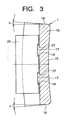
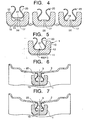
- a balance weight for a wheel of a two-wheel vehicle will be explained with reference to FIGS. 1 - 7.
- a total weight of a balance weight 1 for a wheel of a two-wheel vehicle can be determined by conducting a balancing test of the wheel of a two-wheel vehicle mounted with a tire.
- a length L in an axial direction of the balance weight 1 i.e., a longitudinal direction thereof, which is the same as a circumferential direction of a wheel rim
- a width W of the balance weight 1 are determined depending on the total weight of the balance weight 1.
- the balance weight 1 is mounted to a rib 3 which protrudes inwardly in a radial direction of a wheel rim 2.
- the rib 3 extends in a circumferential direction of the wheel rim 2 at a width center of the wheel rim 2 so as to reinforce the wheel rim 2.
- the balance weight 1 as illustrated in FIGS. 1 - 5, includes a weight body 10 and a clip 20.
- the weight body 10 is made from metal other than lead having a relative high specific density, for example, iron and copper.
- the weight body 10 is preferably made from cast steel, for example, JIS • FCD400, or ductile cast iron, where the weight body 10 is manufactured by casting.
- the material is not limited to cast steel, but may be forged steel. Accordingly, the balance weight 1 according to the present invention contains no lead.
- the weight body 10 includes a groove bottom wall 11 and a pair of groove side walls 12 connected to opposite width ends of the groove bottom wall 11.
- the weight body 10 includes a groove 13 for mounting the clip 20 therein.
- the groove 13 extends over an entire length of the weight body 10 in a longitudinal direction thereof and has a transverse cross-section of the form of a U-letter.
- the clip 20 is made from spring-steel and is preferably made from, for example, a material equivalent to JIS • SK5.
- the clip 20 is manufactured in the form of, for example, a spring plate that is provided with spring-elasticity, and has a thickness of 0.4mm and a hardness of HRC 42-60 at a surface of the spring plate after heat-treated.
- the clip 20 includes a bottom portion 21 and a pair of arms 22 connected to opposite width ends of the bottom portion 21.
- Each of the pair of arms 22 includes (a) a first, inclining portion 23 extending toward an opposite arm of the pair of arms 22 and in a direction away from the bottom portion 21 of the clip 20, (b) a second, rib-holding portion 24 connected to the first portion 23 and located closest to the opposite arm of the pair of arms 22, and (c) a third, guide portion 25 connected to the second portion 24 and extending in a direction away from the opposite arm of the pair of arms 22 and in the direction away from the clip bottom portion 21.
- the clip 20 is mounted to the weight body 10 at the groove 13 of the weight body 10.
- the third, guide portion 25 is located outside the groove 13 of the weight body 10.
- the clip 20 is mounted to the groove bottom wall 11 of the weight body 10 with the bottom portion 21 of the clip 20 contacting closely to the groove bottom wall 11 of the weight body 10, and is fixed to the groove bottom wall 11 at the bottom portion 21 of the clip 20.
- a connecting portion between the bottom portion 21 and the arm 22 includes a curved portion 26.
- the curved portion 26 contacts closely to a curved inner surface 14 of a connecting portion between the groove bottom wall 11 and a corresponding one of the pair of the groove side walls 12 of the weight body 10, and is also held by the curved inner surface 14.
- the distance between a pair of the rib-holding portions 24 of the clip 20 is smaller than the thickness of the rib 3.
- the pair of rib-holding portions 24 of the clip 20 hold the rib 3 therebetween with the spring-elasticity thereof.
- the groove bottom wall 11 of the weight body 10 has an outside surface 15, opposite to the groove 13, which is curved in a longitudinal direction of the weight body 10.
- the curved configuration includes the shape of an arc coaxial with the wheel, which makes the balance weight 1 fit to the wheel rim 2 when mounted to the rib 3.
- an inclination angle ⁇ is provided such that a distance between the opposite longitudinal ends 16 increases in a radially outward direction of the wheel.
- the inclination angle ⁇ facilitates a die to release from the weight body 10 when the weight body 10 is cast or forged.
- the inclination angle ⁇ is preferably 2-3°.
- the environmental problem existing in the conventional balance weight is removed, since the weight body 10 and the clip 20 are made from metals other than lead, for example, iron and steel.
- the balance weight 1 is mounted to the rib 3 of the wheel rim 2 of a two-wheel vehicle by inserting the rib 30 into the clip 20 of the balance weight 2. Since the pair of guide portions 25 are provided in the opposite end portions of the clip 20 and the pair of guide portions 25 are inclined in a direction away from each other, the rib 3 can be smoothly inserted into the clip 20.
- the rib-holding portions 24 of the clip 20 can hold the rib 3 therebetween with spring-elasticity.
- the balance weight 1 can be mounted to the wheel rim 2 of the wheel of a two-wheel vehicle only by inserting the rib 3 into the clip 20, thereby making the mounting of the balance weight 1 to the wheel easy. Further, after the balance weight 1 is mounted to the wheel, the balance weight 1 does not drop from the rib 3, since the clip 20 holds the rib 3 with the spring-elasticity.
- the rib 3 has such a cross-section that a rib end portion, that is, an innermost portion of the rib 3 in a radial direction of the wheel, is formed wider than a remaining portion of the rib 3, which makes coupling of the balance weight 1 to the rib 3 more reliable.
- the rib 3 may have a cross-sectional shape having a constant thickness. In the case of the constant thickness, since a centrifugal force acts on the balance weight 1 during rotation of the wheel, the balance weight 1 is pushed toward the wheel rim 2 and is prevented from dropping from the rib 3.
- the weight body 10 includes at least one protrusion 17 for coupling the clip 20 at the groove bottom wall 11.
- the height of the protrusion 17 is greater than the thickness of the clip 20.
- the diameter of the aperture 27 is equal to or slightly greater than that of the protrusion 17.
- the clip 20 is coupled to the weight body 10, as follows:
- the clip 20 is lined-up with the weight body 10 such that the aperture 27 of the clip 20 is centered on the protrusion 17 of the weight body 10.
- the protrusion 17 of the weight body 10 is then inserted into the aperture 27 of the clip 20, and the bottom portion 21 of the clip 20 is contacted closely to the groove bottom wall 12 of the weight body 10.
- the protrusion 17 of the weight body 10 is then caulked so that a caulked portion 18 has a diameter greater than that of the aperture 27, thereby making the clip 20 undetachably coupled to the weight body 10.
- a projection may be formed at the groove bottom wall 11 of the weight body 10, then the bottom portion 21 of the clip 20 is pushed to the projection. Thereafter, the groove bottom wall 11 of the weight body 10 and the bottom portion 21 of the clip 20 are fixed to each other by projection-welding 41.
- the welding may be conducted before the clip 20 is heat-treated, and then, the clip 20 is heat-treated. This is because if spring steel were welded after the heat-treatment of the clip 20, the spring steel would be tempered due to welding-heat and the spring-elasticity of the spring steel would be lowered. However, since thermal effects due to welding-heat is local in spot-welding 40 and projection-welding 41, the clip 20 may be first heat-treated and then welded to the weight body 10 by spot-welding 40 or by projection-welding 41.
- the clip 20 Since the clip 20 is fixed to the weight body 10 by spot-welding 40 or by projection-welding 41, the spring-elasticity is lost only at a portion of the clip 20. In the case where the welding is first conducted and then the clip 20 is heat-treated, the problem of loss of the spring-elasticity in the clip 20 is absolutely removed.
Landscapes
- Engineering & Computer Science (AREA)
- General Engineering & Computer Science (AREA)
- Mechanical Engineering (AREA)
- Physics & Mathematics (AREA)
- Acoustics & Sound (AREA)
- Aviation & Aerospace Engineering (AREA)
- Tires In General (AREA)
- Clamps And Clips (AREA)
- Vehicle Body Suspensions (AREA)
- Motorcycle And Bicycle Frame (AREA)
- Golf Clubs (AREA)
- Connection Of Plates (AREA)
Claims (9)
- Auswuchtgewicht (1) für ein Rad eines zweirädrigen Fahrzeugs, umfassend:einen Gewichtskörper (10) aus einem anderen Metall als Blei; undeine Klemme (20) aus Federstahl,wobei der Gewichtskörper (10) eine Nut (13) zum Befestigen der Klemme (20) in dieser aufweist und der Gewichtskörper (10) eine Nutenbodenwand (11) und ein Paar Nutenseitenwände (12), die mit gegenüberliegenden Breitseiten der Nutenbodenwand (11) verbunden sind, beinhaltet,wobei die Klemme (20) einen Bodenabschnitt (21) und ein Paar Schenkeln (22), die mit gegenüberliegenden Breitseiten des Bodenabschnitts (21) der Klemme (20) verbunden sind, wobei jeder Schenkel (22) des Paars einen ersten, schrägen Abschnitt (23), der sich in eine vom Bodenabschnitt (21) der Klemme (20) weg führende Richtung zu einem gegenüberliegenden Schenkel des Schenkelpaars (22) erstreckt, und einen zweiten, rippenhaltenden Abschnitt (24) umfasst, der mit dem ersten Abschnitt (23) verbunden ist und am nächsten zum gegenüberliegenden Schenkel des Schenkelpaars (22) angeordnet ist,wobei die Klemme (20) an der Nutenbodenwand (11) des Gewichtskörpers (10) angebracht ist, und wobei der Bodenabschnitt (21) der Klemme (20) die Nutenbodenwand (11) des Gewichtskörpers (10) eng anliegend berührt und wobei die Klemme (20) am Bodenabschnitt (21) der Klemme (20) an der Nutenbodenwand (11) des Gewichtskörpers (10) fixiert ist,wobei der Gewichtskörper (10) einen Vorsprung (17) aufweist, um die Klemme (20) an der Nutenbodenwand (11) des Gewichtskörpers (10) durch Verstemmen des Vorsprungs (17) zu koppeln,
dadurch gekennzeichnet, dass die Klemme (20) eine im Bodenabschnitt (21) der Klemme (20) ausgebildete Öffnung (27) aufweist, wobei die Klemme (20) und der Gewichtskörper (10) durch Einführen des Vorsprungs (17) des Gewichtskörpers (10) in die Öffnung (27) der Klemme (20) vor dem Verstemmen des Gewichtskörpers (10) miteinander gekoppelt sind.2. Auswuchtgewicht (1) nach Anspruch 1, worin der Gewichtskörper (10) aus Eisen hergestellt ist.3. Auswuchtgewicht (1) nach Anspruch 1 oder 2, worin der Gewichtskörper (10) aus duktilem Gusseisen hergestellt ist.4. Auswuchtgewicht (1) nach Anspruch 1, worin der Gewichtskörper (10) aus Gussstahl hergestellt ist.5. Auswuchtgewicht (1) nach einem der Ansprüche 1 bis 4, worin die Klemme (20) und der Gewichtskörper (10) durch Punktschweißen des Bodenabschnitts (21) der Klemme (20) und der Nutenbodenwand (11) des Gewichtskörpers (10) aneinander befestigt sind.6. Auswuchtgewicht (1) nach einem der Ansprüche 1 bis 4, worin die Klemme (20) und der Gewichtskörper (10) durch Buckelschweißen des Bodenabschnitts (21) der Klemme (20) und der Nutenbodenwand (11) des Gewichtskörpers (10) aneinander befestigt sind.7. Auswuchtgewicht (1) nach einem der Ansprüche 1 bis 6, worin die Nutenbodenwand (11) des Gewichtskörpers (10) eine Außenoberfläche (15) aufweist, die in der Längsrichtung des Gewichtskörpers (10) gekrümmt ist.8. Auswuchtgewicht (1) nach einem der Ansprüche 1 bis 7, worin der Gewichtskörper (10) einen U-förmigen Querschnitt aufweist.9. Auswuchtgewicht (1) nach einem der Ansprüche 1 bis 8, worin jeder Schenkel (22) des Paars zudem einen dritten Führungsabschnitt (25) aufweist, der mit dem zweiten Abschnitt (24) verbunden ist und sich in eine vom gegenüberliegenden Schenkel des Schenkelpaars (22) weg führende Richtung und in eine vom Bodenabschnitt (21) der Klemme (20) weg führende Richtung erstreckt.
Applications Claiming Priority (2)
| Application Number | Priority Date | Filing Date | Title |
|---|---|---|---|
| JP2001308680A JP2003113900A (ja) | 2001-10-04 | 2001-10-04 | 二輪車車輪用バランスウエイト |
| JP2001308680 | 2001-10-04 |
Publications (3)
| Publication Number | Publication Date |
|---|---|
| EP1300603A2 EP1300603A2 (de) | 2003-04-09 |
| EP1300603A3 EP1300603A3 (de) | 2003-11-19 |
| EP1300603B1 true EP1300603B1 (de) | 2006-12-13 |
Family
ID=19127950
Family Applications (1)
| Application Number | Title | Priority Date | Filing Date |
|---|---|---|---|
| EP02256905A Expired - Lifetime EP1300603B1 (de) | 2001-10-04 | 2002-10-03 | Radauswuchtgewicht für ein Zweirad |
Country Status (7)
| Country | Link |
|---|---|
| US (1) | US6729694B2 (de) |
| EP (1) | EP1300603B1 (de) |
| JP (1) | JP2003113900A (de) |
| KR (1) | KR100471103B1 (de) |
| CN (1) | CN1279298C (de) |
| DE (1) | DE60216691T2 (de) |
| TW (1) | TW534875B (de) |
Families Citing this family (18)
| Publication number | Priority date | Publication date | Assignee | Title |
|---|---|---|---|---|
| US7093907B2 (en) * | 2002-07-15 | 2006-08-22 | Hennessy Industries, Inc. | Vehicle wheel balance weights |
| US7566101B2 (en) | 2002-07-15 | 2009-07-28 | Hennessy Industries, Inc. | Vehicle wheel balance weights |
| JP4188030B2 (ja) * | 2002-08-23 | 2008-11-26 | 横浜ゴム株式会社 | タイヤ用ホイール |
| WO2004090495A2 (de) * | 2003-04-11 | 2004-10-21 | Franken Industrie Werke Ernst Stenz Gmbh & Co.Kg | Fahrzeugräder-auswuchtgewicht mit konkav oder konvex gekrümmter anlageseite sowie verfahren zu dessen herstellung |
| JP4333616B2 (ja) * | 2005-03-28 | 2009-09-16 | トヨタ自動車株式会社 | 回転体バランス修正部材および回転体バランス修正方法 |
| JP4680729B2 (ja) * | 2005-09-15 | 2011-05-11 | 川崎重工業株式会社 | 車両のホイール |
| DE102006039485A1 (de) * | 2006-08-23 | 2008-02-28 | Dionys Hofmann Gmbh | Ausgleichsgewicht für den Unwuchtausgleich eines Fahrzeugrades |
| JP5265110B2 (ja) * | 2006-12-28 | 2013-08-14 | 上海新明源汽▲車▼配件有限公司 | 自動車車輪用釣合錘及びその製造方法 |
| EP2286111A1 (de) * | 2008-05-02 | 2011-02-23 | Trax Jh Ltd. | Verfahren zur herstellung einer radausgleichsanordnung |
| US7878599B2 (en) * | 2008-07-09 | 2011-02-01 | Perfect Equipment Inc. | Wheel balancing weights with body and mounting clip |
| US7976107B2 (en) * | 2009-01-30 | 2011-07-12 | Lance Okada | Vehicle wheel rim having lateral balance plane |
| US8353670B2 (en) * | 2009-07-30 | 2013-01-15 | Pratt & Whitney Canada Corp. | Axial balancing clip weight for rotor assembly and method for balancing a rotor assembly |
| DE202009013115U1 (de) * | 2009-09-29 | 2010-04-08 | Wagner Federn Gmbh | Wuchtmittel zur Anordnung an rotierende Bauteile, insbesondere an Schaufeln von Ventilatoren und zugehöriger Baukasten |
| US20120067162A1 (en) * | 2010-09-17 | 2012-03-22 | Steven Kollmann | Steering Wheel Armature Weight |
| WO2012119236A1 (en) | 2011-03-08 | 2012-09-13 | Plombco Inc. | Overmolded wheel-balancing weight |
| US9169895B2 (en) | 2011-11-29 | 2015-10-27 | Hennessy Industries, Inc. | Vehicle wheel balance weights |
| USD737116S1 (en) | 2012-03-08 | 2015-08-25 | Plombco Inc. | Wheel-securing clip |
| CN108495534B (zh) * | 2018-05-22 | 2019-11-19 | 湖州旭源电气科技有限公司 | 一种机箱的散热组件及其制造方法 |
Family Cites Families (15)
| Publication number | Priority date | Publication date | Assignee | Title |
|---|---|---|---|---|
| US1889577A (en) * | 1928-08-04 | 1932-11-29 | Packard Motor Car Co | Motor vehicle |
| US2433762A (en) | 1944-08-14 | 1947-12-30 | Harley C Loney Company | Airplane wheel balancing weight |
| FR1114880A (fr) | 1954-08-11 | 1956-04-17 | Perfectionnements apportés à la fixation des masses d'équilibrage des roues de véhicules | |
| US5350220A (en) * | 1993-11-22 | 1994-09-27 | Chrysler Corporation | Vehicle wheel with balance weights |
| US5564792A (en) * | 1994-12-13 | 1996-10-15 | Hayes Wheels International, Inc. | Balancing weight attachment system for a vehicle wheel |
| KR200151132Y1 (ko) * | 1995-12-28 | 1999-07-15 | 정몽규 | 타이어 휠의 밸런스 웨이트 부착구조 |
| KR19980030285A (ko) * | 1996-10-29 | 1998-07-25 | 김영귀 | 밸런스웨이트가 일체로 형성된 타이어휠 |
| KR19980031694U (ko) * | 1996-11-30 | 1998-08-17 | 양재신 | 자동차용 휠의 밸런스 웨이트 |
| JP3847974B2 (ja) | 1998-10-12 | 2006-11-22 | 大豊工業株式会社 | ホイールバランスウェイト |
| EP1069340B1 (de) * | 1999-07-15 | 2004-04-14 | Topy Kogyo Kabushiki Kaisha | Radauswuchtgewicht |
| DE60000713T2 (de) * | 1999-08-20 | 2003-07-03 | Sumitomo Rubber Industries Ltd., Kobe | Radauswuchtgewicht |
| JP2001280423A (ja) | 2000-01-28 | 2001-10-10 | Topy Ind Ltd | 二輪車車輪用バランスウエイト |
| JP2001221289A (ja) | 2000-02-04 | 2001-08-17 | Topy Ind Ltd | 二輪車車輪用バランスウエイト |
| JP2002286097A (ja) * | 2001-01-18 | 2002-10-03 | Topy Ind Ltd | 二輪車車輪用バランスウエイト |
| JP2002257197A (ja) | 2001-02-27 | 2002-09-11 | Topy Ind Ltd | 二輪車車輪用バランスウエイト |
-
2001
- 2001-10-04 JP JP2001308680A patent/JP2003113900A/ja active Pending
-
2002
- 2002-08-30 TW TW091119853A patent/TW534875B/zh not_active IP Right Cessation
- 2002-09-24 KR KR10-2002-0057819A patent/KR100471103B1/ko not_active Expired - Fee Related
- 2002-09-27 CN CNB021435340A patent/CN1279298C/zh not_active Expired - Fee Related
- 2002-10-03 DE DE60216691T patent/DE60216691T2/de not_active Expired - Fee Related
- 2002-10-03 US US10/262,866 patent/US6729694B2/en not_active Expired - Fee Related
- 2002-10-03 EP EP02256905A patent/EP1300603B1/de not_active Expired - Lifetime
Also Published As
| Publication number | Publication date |
|---|---|
| DE60216691T2 (de) | 2007-10-18 |
| CN1410285A (zh) | 2003-04-16 |
| CN1279298C (zh) | 2006-10-11 |
| US20030067208A1 (en) | 2003-04-10 |
| DE60216691D1 (de) | 2007-01-25 |
| EP1300603A3 (de) | 2003-11-19 |
| KR100471103B1 (ko) | 2005-03-08 |
| TW534875B (en) | 2003-06-01 |
| US6729694B2 (en) | 2004-05-04 |
| JP2003113900A (ja) | 2003-04-18 |
| KR20030029016A (ko) | 2003-04-11 |
| EP1300603A2 (de) | 2003-04-09 |
Similar Documents
| Publication | Publication Date | Title |
|---|---|---|
| EP1300603B1 (de) | Radauswuchtgewicht für ein Zweirad | |
| EP1069340B1 (de) | Radauswuchtgewicht | |
| US5913735A (en) | Metallic golf club head having a weight and method of manufacturing the same | |
| US5935019A (en) | Metallic hollow golf club head | |
| US6572088B2 (en) | Vibration isolating bushing | |
| US20090278397A1 (en) | Vehicle wheel balance weights | |
| EP1110756B1 (de) | Rollenträger für Rad und Herstellungsverfahren | |
| US20050104439A1 (en) | Wheel weight with body having recess and clip secured therein | |
| US20020125382A1 (en) | One-piece mounting bracket and vehicle damper assembly and mounting method | |
| EP1225367B1 (de) | Auswuchtsgewicht für Zweiradfahrzeug | |
| US6454060B1 (en) | Vehicle suspension monotube strut base cup assembly | |
| JPH04102710A (ja) | 万能連結器 | |
| EP3943209A1 (de) | Verfahren zur herstellung eines stabilisators | |
| US6394472B1 (en) | Steering knuckle | |
| US5934876A (en) | Blower wheel assembly with steel hub having cold-headed lugs, and method of making same | |
| JP3663066B2 (ja) | バランスウエイト部材 | |
| JPH11294541A (ja) | ホイールバランシングウエイト | |
| US7117982B2 (en) | Shock absorber | |
| JPH11257435A (ja) | ホイールバランシングウエイト | |
| JPH04351335A (ja) | 防振ゴム取付構造 | |
| EP1197352A2 (de) | Radnabe und Herstellungsverfahren einer Radnabeneinheit | |
| JP2002257197A (ja) | 二輪車車輪用バランスウエイト | |
| JP2000046120A (ja) | ホイ−ル用バランスウェイト | |
| JP3112148U (ja) | ホイールバランスウエイト | |
| JP2001221290A (ja) | 二輪車車輪用バランスウエイト |
Legal Events
| Date | Code | Title | Description |
|---|---|---|---|
| PUAI | Public reference made under article 153(3) epc to a published international application that has entered the european phase |
Free format text: ORIGINAL CODE: 0009012 |
|
| 17P | Request for examination filed |
Effective date: 20021023 |
|
| AK | Designated contracting states |
Kind code of ref document: A2 Designated state(s): AT BE BG CH CY CZ DE DK EE ES FI FR GB GR IE IT LI LU MC NL PT SE SK TR Designated state(s): AT BE BG CH CY CZ DE DK EE ES FI FR GB GR IE IT LI LU MC NL PT SE SK TR |
|
| AX | Request for extension of the european patent |
Extension state: AL LT LV MK RO SI |
|
| PUAL | Search report despatched |
Free format text: ORIGINAL CODE: 0009013 |
|
| AK | Designated contracting states |
Kind code of ref document: A3 Designated state(s): AT BE BG CH CY CZ DE DK EE ES FI FR GB GR IE IT LI LU MC NL PT SE SK TR |
|
| AX | Request for extension of the european patent |
Extension state: AL LT LV MK RO SI |
|
| 17Q | First examination report despatched |
Effective date: 20040317 |
|
| AKX | Designation fees paid |
Designated state(s): DE FR GB IT |
|
| GRAP | Despatch of communication of intention to grant a patent |
Free format text: ORIGINAL CODE: EPIDOSNIGR1 |
|
| GRAS | Grant fee paid |
Free format text: ORIGINAL CODE: EPIDOSNIGR3 |
|
| GRAA | (expected) grant |
Free format text: ORIGINAL CODE: 0009210 |
|
| AK | Designated contracting states |
Kind code of ref document: B1 Designated state(s): DE FR GB IT |
|
| REG | Reference to a national code |
Ref country code: GB Ref legal event code: FG4D |
|
| REF | Corresponds to: |
Ref document number: 60216691 Country of ref document: DE Date of ref document: 20070125 Kind code of ref document: P |
|
| ET | Fr: translation filed | ||
| PLBE | No opposition filed within time limit |
Free format text: ORIGINAL CODE: 0009261 |
|
| STAA | Information on the status of an ep patent application or granted ep patent |
Free format text: STATUS: NO OPPOSITION FILED WITHIN TIME LIMIT |
|
| 26N | No opposition filed |
Effective date: 20070914 |
|
| PGFP | Annual fee paid to national office [announced via postgrant information from national office to epo] |
Ref country code: DE Payment date: 20071025 Year of fee payment: 6 |
|
| PGFP | Annual fee paid to national office [announced via postgrant information from national office to epo] |
Ref country code: IT Payment date: 20071030 Year of fee payment: 6 |
|
| PGFP | Annual fee paid to national office [announced via postgrant information from national office to epo] |
Ref country code: GB Payment date: 20071019 Year of fee payment: 6 Ref country code: FR Payment date: 20071024 Year of fee payment: 6 |
|
| GBPC | Gb: european patent ceased through non-payment of renewal fee |
Effective date: 20081003 |
|
| REG | Reference to a national code |
Ref country code: FR Ref legal event code: ST Effective date: 20090630 |
|
| PG25 | Lapsed in a contracting state [announced via postgrant information from national office to epo] |
Ref country code: IT Free format text: LAPSE BECAUSE OF NON-PAYMENT OF DUE FEES Effective date: 20081003 Ref country code: DE Free format text: LAPSE BECAUSE OF NON-PAYMENT OF DUE FEES Effective date: 20090501 |
|
| PG25 | Lapsed in a contracting state [announced via postgrant information from national office to epo] |
Ref country code: FR Free format text: LAPSE BECAUSE OF NON-PAYMENT OF DUE FEES Effective date: 20081031 |
|
| PG25 | Lapsed in a contracting state [announced via postgrant information from national office to epo] |
Ref country code: GB Free format text: LAPSE BECAUSE OF NON-PAYMENT OF DUE FEES Effective date: 20081003 |