EP1300611B1 - Verfahren zum Verwalten einer Getriebesteuereinheit im Kickdown-Modus - Google Patents
Verfahren zum Verwalten einer Getriebesteuereinheit im Kickdown-Modus Download PDFInfo
- Publication number
- EP1300611B1 EP1300611B1 EP20020292455 EP02292455A EP1300611B1 EP 1300611 B1 EP1300611 B1 EP 1300611B1 EP 20020292455 EP20020292455 EP 20020292455 EP 02292455 A EP02292455 A EP 02292455A EP 1300611 B1 EP1300611 B1 EP 1300611B1
- Authority
- EP
- European Patent Office
- Prior art keywords
- value
- stage
- speed
- vehicle
- during
- Prior art date
- Legal status (The legal status is an assumption and is not a legal conclusion. Google has not performed a legal analysis and makes no representation as to the accuracy of the status listed.)
- Expired - Lifetime
Links
- 238000000034 method Methods 0.000 title claims description 22
- 230000005540 biological transmission Effects 0.000 title description 2
- XDDAORKBJWWYJS-UHFFFAOYSA-N glyphosate Chemical compound OC(=O)CNCP(O)(O)=O XDDAORKBJWWYJS-UHFFFAOYSA-N 0.000 title description 2
- 238000012360 testing method Methods 0.000 claims description 51
- 230000009467 reduction Effects 0.000 claims description 16
- 230000001133 acceleration Effects 0.000 claims description 10
- 230000015654 memory Effects 0.000 claims description 8
- 230000006870 function Effects 0.000 claims description 7
- 230000008859 change Effects 0.000 claims description 5
- 230000008569 process Effects 0.000 claims description 4
- 238000004364 calculation method Methods 0.000 claims description 3
- 230000004044 response Effects 0.000 claims description 2
- 238000003860 storage Methods 0.000 description 5
- 238000010010 raising Methods 0.000 description 4
- 230000000881 depressing effect Effects 0.000 description 2
- 238000001514 detection method Methods 0.000 description 2
- 238000011084 recovery Methods 0.000 description 2
- 230000008901 benefit Effects 0.000 description 1
- 230000001965 increasing effect Effects 0.000 description 1
- 230000010354 integration Effects 0.000 description 1
- 230000007704 transition Effects 0.000 description 1
- 230000001960 triggered effect Effects 0.000 description 1
Images
Classifications
-
- F—MECHANICAL ENGINEERING; LIGHTING; HEATING; WEAPONS; BLASTING
- F16—ENGINEERING ELEMENTS AND UNITS; GENERAL MEASURES FOR PRODUCING AND MAINTAINING EFFECTIVE FUNCTIONING OF MACHINES OR INSTALLATIONS; THERMAL INSULATION IN GENERAL
- F16H—GEARING
- F16H61/00—Control functions within control units of change-speed- or reversing-gearings for conveying rotary motion ; Control of exclusively fluid gearing, friction gearing, gearings with endless flexible members or other particular types of gearing
- F16H61/02—Control functions within control units of change-speed- or reversing-gearings for conveying rotary motion ; Control of exclusively fluid gearing, friction gearing, gearings with endless flexible members or other particular types of gearing characterised by the signals used
- F16H61/0202—Control functions within control units of change-speed- or reversing-gearings for conveying rotary motion ; Control of exclusively fluid gearing, friction gearing, gearings with endless flexible members or other particular types of gearing characterised by the signals used the signals being electric
- F16H61/0204—Control functions within control units of change-speed- or reversing-gearings for conveying rotary motion ; Control of exclusively fluid gearing, friction gearing, gearings with endless flexible members or other particular types of gearing characterised by the signals used the signals being electric for gearshift control, e.g. control functions for performing shifting or generation of shift signal
- F16H61/0213—Control functions within control units of change-speed- or reversing-gearings for conveying rotary motion ; Control of exclusively fluid gearing, friction gearing, gearings with endless flexible members or other particular types of gearing characterised by the signals used the signals being electric for gearshift control, e.g. control functions for performing shifting or generation of shift signal characterised by the method for generating shift signals
-
- F—MECHANICAL ENGINEERING; LIGHTING; HEATING; WEAPONS; BLASTING
- F16—ENGINEERING ELEMENTS AND UNITS; GENERAL MEASURES FOR PRODUCING AND MAINTAINING EFFECTIVE FUNCTIONING OF MACHINES OR INSTALLATIONS; THERMAL INSULATION IN GENERAL
- F16H—GEARING
- F16H59/00—Control inputs to control units of change-speed- or reversing-gearings for conveying rotary motion
- F16H59/14—Inputs being a function of torque or torque demand
- F16H59/18—Inputs being a function of torque or torque demand dependent on the position of the accelerator pedal
- F16H59/20—Kickdown
Definitions
- the invention relates to a method for managing a calculator controlling the passage of reports of a box of motor vehicle speeds according to characteristics of the preamble of claim 1.
- kick-down security function which allows to downgrade one or more reports of transmission for the vehicle to benefit from a recovery of power, for example to perform an overshoot.
- This function is usually triggered when the driver of the vehicle depresses the vehicle's accelerator pedal fully.
- the passage of the reports of the boxes of automatic speeds in normal mode is governed by a calculator operating according to a map comprising zones each associated with the commitment of a specific report.
- the calculator determines the operating point of the vehicle, which is defined in particular by the speed of the vehicle and the position of the accelerator pedal, which is itself expressed in the form a percentage between 0 and 100%, the percentage nil corresponding to the relaxed position of the accelerator pedal and the percentage of 100%, corresponding to the position of maximum depression of the accelerator pedal slowly.
- the calculator controls the passage of the corresponding report.
- Each area associated with a report is separated from the area neighbor by a curve associated with a law of passage, this law being comparable to a curve which is also a function of the speed of the vehicle and the position of the accelerator pedal.
- this configuration has the disadvantage of can only allow a simple downshift since, for a determined speed of the vehicle, the calculator can not, when maximum and rapid depression of the accelerator pedal or "kick" is detected, that break down the report shift into one switch to normal mode followed by a switch to kick mode. At during this last passage in kick mode, the calculator determines the passage of an operating point, located at the limit of the last encountered area associated with a report in normal mode, to another operating point located in the kick box associated with rank report immediately inferior.
- the invention proposes a method of managing a computer of the type described above which operates independently of the laws of passage associated with the normal operating mode.
- the method comprises at least one mode of normal operation "NORM" in which the passage of each report is governed by an associated law which is a function of the position of a vehicle accelerator pedal and speed instantaneous vehicle.
- the passage of reports in mode Normal "NORM" is indexed on a map (no represented) with zones each associated with commitment to a specific relationship.
- the calculator determines the point of operation of the vehicle, which is defined in particular by the speed of the vehicle and the position of the accelerator pedal, which is expressed as a percentage between 0 and 100%, the null percentage corresponding to the relaxed position the accelerator pedal and the percentage of 100%, corresponding to the position of maximum depression of the pedal accelerator performed slowly.
- the calculator controls the passage of the corresponding report. This configuration being known from the state of the art, it will not be not developed more explicitly in the present description.
- the method comprises at least one kick mode of operation "KICK", in which, in response an information "kick (t)" representative of a depression maximum of the accelerator pedal, the computer controls the transition from lower order relationships to that which would be determined by the calculator in "NORM” mode of normal operation to cause maximum acceleration of the vehicle.
- KICK kick mode of operation
- the course of the steps "ET1" and “'ET2” requires the entry of the information "kick (t)” representative of the detection of a maximum depression of the accelerator pedal and information “Vinst (t)” representative of the instantaneous speed of vehicle.
- the information “kick (t)” can take the unit values “1” or zero “0” according to a maximum depression of the pedal accelerator is detected or not, and the information “Vinst (t)" representative of the instantaneous speed of the vehicle can take all values in the speed value range according to which the vehicle is likely to roll.
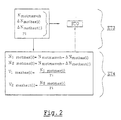
- the method comprises a third step “ET3" independent memory, preliminary to the first and second steps “ET1” and “ET2”, during which the calculator stores in a memory "STO” different values, and a fourth computing step “ET4" during which the calculator calculates other values according to the values previously obtained during the third stage "ET3" then the stores in the memory "STO".
- the "RCL” set of these values can then be recalled during the first and second stages “ET1" and “ET2" to allow the flow of the process.
- the computer stores in the memory "STO” a value "N motmaxveh " representative of a maximum allowable engine speed of the vehicle. This value corresponds to the maximum speed value that the engine of the vehicle can theoretically provide.
- the computer also stores in the memory "STO” a lower speed threshold value " ⁇ N motbas (i) " associated with each report “i” of reduction.
- This threshold value is intended, as will be seen later, to lower, according to each report “i", the value “N motmaxveh " representative of the maximum allowable engine speed of the vehicle, and it will be particularly used during the second step “ET2" of the method.
- the computer also stores in the memory "STO” a higher speed threshold value “ ⁇ N mothaut (i) " associated with each report “i” of reduction.
- This threshold value is intended, as will be seen later, to lower, according to each report “i", the value “N motmaxveh " representative of the maximum allowable engine speed of the vehicle, and it will be particularly used during the third step "ET3" of the process.
- the computer stores a reduction value r i "associated with each gear ratio” i ", and a determined speed difference value” V ⁇ ", which will be used during steps “ET1" and "ET2".
- the method comprises a fourth "ET4" calculation step, which is also preliminary to the first and second "ET1" and “ET2” steps, and during which the calculator calculates a value "N1 motmax (i) ", representative of a maximum allowable engine speed for each report "i" during the first step "ET1".
- N1 motmax (i) N motmaxveh - ⁇ N motbas (i) ,
- V1 maxbas (i) is representative of a maximum permissible speed of the vehicle for the ratio (i) during the first step (ET1).
- V1 maxbas (i) is equal to the quotient of the value "N1 motmax (i) ", representative of the maximum allowable engine speed for each ratio “i” by the reduction value "r i " associated with the ratio "i ":
- V1 maxbas (i) N1 motmax (i) / r i ,
- the computer also calculates a value "N2 motmax (i) ", which is representative of a maximum allowable engine speed for each report "i" during the second stage "ET2".
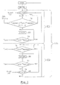
- the first step "ET1" of determination of the objective report first involves a first sub-step “T1" test during which the calculator compare an instant kick (t) kick value associated with depressing the accelerator pedal to the unit value "1".
- the computer commands the return to the "NORM" mode of normal operation if the value "kick (t)" corresponds to the value zero "0", ie if the depression of the pedal is not maximum or if the instant kick (t) kick value is equal to the unit value "1", triggers a second substep "T2" test.
- the calculator determines, by choosing in the values previously calculated in step "ET4", the value "V1 maxbas (i) " of maximum permissible speed of the vehicle which is the most immediately higher than the value "Vinst (t)" representative of the instantaneous speed of the vehicle.
- Vsbas (i ET1 ) V1 maxbas (i) - V ⁇ ,
- Vinst (t) representative of the instantaneous speed of the vehicle is greater than the value of the speed "Vsbas (i ET1 )" of admissible threshold, the computer triggers the second stage “ET2" of upshifting, or otherwise it returns to the fourth sub-test step "T4" previously described.
- the second step “ET2" raising reports firstly comprises a fifth sub-step “T5" test during which, the value “Vinst (t)” having been introduced again in the calculator, it determines, by choosing from the values previously calculated in step "ET4", the value "V2 max high (i) " representative of the maximum permissible speed of the vehicle which is the most immediately lower than the value "Vinst (t)” representative the instantaneous speed of the vehicle.
- the computer compares the value "Vinst (t)" representative of the instantaneous speed of the vehicle to a speed value "Vsbas (i ET2 )" of admissible threshold during the second stage (ET2).
- Vsbas (i ET2 ) of admissible threshold during the second stage (ET2).
- Vsbas (i ET2 ) V2 maxhaut (i) + V ⁇ ,
- Vinst (t) representative of the instantaneous vehicle speed is greater than the value of the "Vshaut (i ET2 )" threshold speed, the computer triggers an eighth test sub-step “T8" or else otherwise it returns to the sixth substep "E6" execution.
- the eighth sub-step “T8" test is a step of check during which the calculator checks that the "kick” is always requested by the driver of the vehicle. For this purpose, the calculator again compares the instant "kick (t)" value kick associated with depressing the accelerator pedal at the unit value "1". It triggers the return to the fifth substep "T5" test, ie the continuation of the rise of reports, if the instant kick (t) value of kick is equal to the unit value "1", or else it commands the return to the mode "NORM" of normal operation.
- the invention thus makes it possible to have a method of management of a computer controlling the passage of reports a gearbox of a motor vehicle that frees itself completely laws of passage of said box.
Landscapes
- Engineering & Computer Science (AREA)
- General Engineering & Computer Science (AREA)
- Mechanical Engineering (AREA)
- Control Of Transmission Device (AREA)
Claims (5)
- Verfahren zur Verwaltung eines Rechners, der den Übergang der Gänge eines Getriebes eines Kraftfahrzeugs steuert, von dem Typ, der mindestens einen Normalbetriebsmodus (NORM) aufweist, in dem der Übergang eines jeden Gangs durch eine zugeordnete Regel geregelt wird, die von der Stellung eines Gaspedals des Fahrzeugs und der momentanen Geschwindigkeit des Fahrzeugs abhängt, und von dem Typ, der mindestens einen Betriebsmodus namens "Kick" aufweist, in dem als Antwort auf eine Information (kick(t)), die für ein maximales Durchdrücken des Gaspedals steht, der Rechner den Übergang der Gänge mit einem Rang anweist, der niedrigerer ist, als derjenige, der vom Rechner im Normalbetriebsmodus (NORM) bestimmt würde, um eine maximale Beschleunigung des Fahrzeugs hervorzurufen,
dadurch gekennzeichnet, dass der Betriebsmodus Kick den Übergang der Gänge unabhängig von den Regeln steuert, die ihnen im Normalbetriebsmodus zugeordnet sind, und dadurch, dass er mindestens aufweist:einen ersten Schritt (ET1) der Bestimmung eines objektiven Gangs, der die maximale Beschleunigung des Fahrzeugs unter Berücksichtigung seiner momentanen Geschwindigkeit hervorruft,einen zweiten Schritt (ET2) des Anstiegs der Gänge, im Laufe dessen der Rechner, ausgehend vom objektiven Gang, der zuvor bestimmt wurde, den Anstieg der Gänge unter Berücksichtigung der momentanen Geschwindigkeit des Fahrzeugs steuert, um die maximale Beschleunigung des Fahrzeugs hervorzurufen. - Verfahren gemäß dem vorhergehenden Anspruch, dadurch gekennzeichnet, dass es einen unabhängigen dritten Schritt (ET3) des Speicherns (STO) aufweist, der den ersten und zweiten Schritt vorbereitet, im Laufe dessen der Rechner speichert:einen Wert (Nmotmaxveh), der für eine maximal zulässige Motordrehzahl des Fahrzeugs steht,einen unteren Schwellenwert der Drehzahl (ΔNmotbas(i)), der jedem Untersetzungsverhältnis (i) zugeordnet ist,einen oberen Schwellenwert der Drehzahl (ΔNmothaut(i)), der jedem Untersetzungsverhältnis (i) zugeordnet ist,einen Wert der Verringerung (ri), der jedem Untersetzungsverhältnis (i) zugeordnet ist, undeinen bestimmten Wert (VΔ) der Abweichung der Geschwindigkeit.
- Verfahren gemäß dem vorhergehenden Anspruch, dadurch gekennzeichnet, dass es einen vierten Schritt (ET4) des Berechnens aufweist, der den ersten und zweiten Schritt vorbereitet und der dem dritten Schritt (ET3) folgt und im Laufe dessen der Rechner berechnet:einen Wert (N1motmax(i)), der für eine maximal zulässige Motordrehzahl für jeden Gang (i) während des ersten Schritts (ET1) steht und der gleich der Differenz zwischen dem Wert (Nmotmaxveh), der für die maximal zulässige Motordrehzahl des Fahrzeugs steht, und dem unteren Drehzahlschwellenwert (ΔNmotbas(i)) ist:einen Wert (N2motmax(i)), der für eine maximal zulässige Motordrehzahl für jeden Gang (i) während des zweiten Schritts (ET2) steht, und der gleich der Differnz zwischen dem Wert (Nmotmaxveh), der für die maximal zulässige Motordrehzahl des Fahrzeugs steht, und dem oberen Drehzahlschwellenwert (ΔNmothaut(i)) ist:einen Wert (V1maxbas(i)), der für eine maximal zulässige Geschwindigkeit des Fahrzeugs für den Gang (i) im Lauf des ersten Schritts (ET1) steht, und der gleich dem Quotienten aus dem Wert (N1motmax(i)), der für die maximal zulässige Motordrehzahl für jeden Gang (i) steht, und dem Wert der Verringerung (ri) ist, der dem Gang (i) zugeordnet ist:einen Wert (V2maxhaut(i)), der für eine maximal zulässige Geschwindigkeit des Fahrzeugs für den Gang (i) im Lauf des zweiten Schritts (ET2) steht, und der gleich dem Quotienten aus dem Wert (N2motmax(i)), der für die maximal zulässige Motordrehzahl für jeden Gang (i) steht, und dem Wert der Verringerung (ri) ist, der dem Gang (i) zugeordnet ist:
- Verfahren gemäß dem vorhergehenden Anspruch, dadurch gekennzeichnet, dass der erste Schritt (ET1) der Bestimmung des objektiven Gangs umfasst:einen ersten Unterschritt (T1) des Testens, im Laufe dessen der Rechner einen momentanen Wert (Kick (t)) des Kicks, der dem Drücken des Gaspedals zugeordnet ist, mit einem unitären Wert (1) vergleicht, um einen zweiten Unterschritt (T2) des Testens auszulösen, wenn der momentane Wert (kick(t)) des Kicks gleich dem unitären Wert (1) ist, bzw. andernfalls die Rückkehr in den Normalbetriebsmodus (NORM) anweist,den zweiten Unterschritt (T2) des Testens, im Laufe dessen der Rechner den Wert (V1maxbas(i)) der maximal zulässigen Geschwindigkeit für jeden Gang (iET1) bestimmt, der derjenige ist, der am unmittelbarsten höher ist als ein Wert (Vinst(t)), der für die momentane Geschwindigkeit des Fahrzeugs steht,einen dritten Unterschritt (E3) des Ausführens, im Laufe dessen der Rechner den Übergang des Gangs (iET1) anweist, der dem Wert (V1maxbas(i)) zugeordnet ist, der derjenige ist, der am unmittelbarsten höher ist als der Wert (Vinst(t)), der im zweiten Unterschritt (T2) des Testens bestimmt wurde,einen vierten Unterschritt des Testens (T4), im Laufe dessen der Rechner den Wert (Vinst(t)), der für die momentane Geschwindigkeit des Fahrzeugs steht, mit einem im Lauf des ersten Schritts (ET1) zulässigen Geschwindigkeitsschwellenwert (Vsbas(iET1)) vergleicht, der gleich der Differenz zwischen dem Wert (V1maxbas(i)), der im Lauf des zweiten Unterschritts des Tests bestimmt wird, und dem ermittelten Wert VΔ der Abweichung der Geschwindigkeit ist,
- Verfahren gemäß dem vorhergehenden Anspruch, dadurch gekennzeichnet, dass der zweite Schritt (ET2) des Anstiegs der Gänge umfasst:einen fünften Unterschritt (T5) des Testens, im Laufe dessen der Rechner den Wert (V2maxhaut(i)) bestimmt, der für die maximal zulässige Geschwindigkeit des Fahrzeugs für den Gang (iET2) steht, der derjenige ist, der am unmittelbarsten niedriger ist als der Wert (Vinst(t)), der für die momentane Geschwindigkeit des Fahrzeugs steht,einen sechsten Unterschritt (E6) des Ausführens, im Laufe dessen der Rechner den Übergang des Gangs (iET2) anweist, der dem Wert (V2maxhaut(i)) zugeordnet ist und der für die maximal zulässige Geschwindigkeit des Fahrzeugs steht, der im fünften Unterschritt (T5) bestimmt wurde,einen siebten Unterschritt (T7) des Testens, im Laufe dessen der Rechner den Wert (Vinst(t)), der für die momentane Geschwindigkeit des Fahrzeugs steht, mit einem im Lauf des zweiten Schritts (ET2) zulässigen Geschwindigkeitsschwellenwert (Vshaut(iET2)) vergleicht, der gleich der Summe des Wertes (V2maxhaut(i)), der im Lauf des fünften Unterschritts des Testens (T5) bestimmt wurde, und dem bestimmten Wert VΔ des Abweichens der Geschwindigkeit ist:
Applications Claiming Priority (2)
| Application Number | Priority Date | Filing Date | Title |
|---|---|---|---|
| FR0112741A FR2830595B1 (fr) | 2001-10-04 | 2001-10-04 | Procede de gestion d'un calculateur de boite de vitesses en mode de kick |
| FR0112741 | 2001-10-04 |
Publications (2)
| Publication Number | Publication Date |
|---|---|
| EP1300611A1 EP1300611A1 (de) | 2003-04-09 |
| EP1300611B1 true EP1300611B1 (de) | 2005-07-27 |
Family
ID=8867899
Family Applications (1)
| Application Number | Title | Priority Date | Filing Date |
|---|---|---|---|
| EP20020292455 Expired - Lifetime EP1300611B1 (de) | 2001-10-04 | 2002-10-04 | Verfahren zum Verwalten einer Getriebesteuereinheit im Kickdown-Modus |
Country Status (4)
| Country | Link |
|---|---|
| EP (1) | EP1300611B1 (de) |
| DE (1) | DE60205189T2 (de) |
| ES (1) | ES2242836T3 (de) |
| FR (1) | FR2830595B1 (de) |
Family Cites Families (4)
| Publication number | Priority date | Publication date | Assignee | Title |
|---|---|---|---|---|
| JP2581782B2 (ja) * | 1988-11-28 | 1997-02-12 | 日産自動車株式会社 | 自動変速機の変速制御装置 |
| SE9901349L (sv) * | 1999-04-16 | 2000-03-20 | Scania Cv Ab | Förfarande och anordning för styrning av en automatiserad växellåda |
| US6134495A (en) * | 1999-12-17 | 2000-10-17 | Daimlerchrysler Corporation | Throttle rate desired acceleration kickdowns |
| DE19961979A1 (de) * | 1999-12-22 | 2001-08-09 | Zahnradfabrik Friedrichshafen | Kick-down-Schaltdrehzahloptimierung für ein Automatgetriebe eines Kraftfahrzeugs |
-
2001
- 2001-10-04 FR FR0112741A patent/FR2830595B1/fr not_active Expired - Fee Related
-
2002
- 2002-10-04 EP EP20020292455 patent/EP1300611B1/de not_active Expired - Lifetime
- 2002-10-04 ES ES02292455T patent/ES2242836T3/es not_active Expired - Lifetime
- 2002-10-04 DE DE2002605189 patent/DE60205189T2/de not_active Expired - Fee Related
Also Published As
| Publication number | Publication date |
|---|---|
| FR2830595A1 (fr) | 2003-04-11 |
| ES2242836T3 (es) | 2005-11-16 |
| DE60205189T2 (de) | 2006-04-20 |
| EP1300611A1 (de) | 2003-04-09 |
| DE60205189D1 (de) | 2005-09-01 |
| FR2830595B1 (fr) | 2004-01-16 |
Similar Documents
| Publication | Publication Date | Title |
|---|---|---|
| KR100335916B1 (ko) | 차량용 자동 변속기의 변속 제어 방법 | |
| FR2866088A1 (fr) | Systeme de commande pour transmission variable en continu du type a courroie | |
| FR2732276A1 (fr) | Systeme a boite de vitesses mecanique robotisee | |
| WO1996031712A2 (fr) | Systeme a boite de vitesses mecanique robotisee comprenant des moyens de commande perfectionnes a l'arret du vehicule | |
| FR3074534A1 (fr) | Procede de controle d’un moteur de vehicule automobile | |
| EP1300611B1 (de) | Verfahren zum Verwalten einer Getriebesteuereinheit im Kickdown-Modus | |
| EP0991880B1 (de) | Verfahren zum steuern der zurückschaltungsgänge bei automatikgetrieben | |
| JP3838422B2 (ja) | 車両用自動変速機の変速制御装置およびその方法 | |
| FR2697884A1 (fr) | Dispositif de commutation pour une boîte de vitesses. | |
| EP1733157A1 (de) | Für servobremsung verwendetes verfahren zur steuerung von automatischem oder automatisiertem getriebeherunterschalten | |
| EP1792106B1 (de) | Verfahren zur steuerung im multibedienungsmodus eines automatikgetriebes für ein kraftfahrzeug, besonders für leerlaufbetrieb mit nichtangezogener bremse und dazugehörige vorrichtung | |
| KR100598804B1 (ko) | 자동 변속 차량의 엔진 토크 저감 제어방법 | |
| EP0961890A1 (de) | Verfahren zur erkennung von rutschigen bodenflächen und der blockierung der räder eines fahrzeuges, automatisches getriebe das dieses verfahren anwendet und kraftfahrzeug das mit solchem getriebe ausgestattet ist | |
| EP1791715B1 (de) | Verfahren zur steuerung des mehrbetriebsmodus eines automatikgetriebes für ein kraftfahrzeug, im besonderen für leerlaufbetrieb mit angezogener bremse und dazugehörige vorrichtung | |
| EP1753949B1 (de) | Verfahren und vorrichtung zur steuerung des automatikgetriebes eines kraftfahrzeugs | |
| WO1996031360A1 (fr) | Systeme de commande pour boite de vitesse mecanique comprenant des moyens empechant le derapage des roues | |
| JP2000337503A (ja) | 自動変速機の変速制御装置 | |
| EP1344963B1 (de) | Verfahren und Vorrichtung zur Schaltungssteuerung in einem Automatik- oder automatisierten Getriebe | |
| EP3938261B1 (de) | Verfahren zur regulierung der geschwindigkeit eines fahrzeugs | |
| EP1716033A1 (de) | Vorrichtung und verfahren zum antrieb einer kraftfahrzeug-zugkette, deren übertragungsglieder einen automatisch schaltbaren untersetzungsmodus besitzen, und mit der vorrichtung versehenes kraftfahrzeug | |
| EP1807642B1 (de) | VERFAHREN ZUR STEUERUNG eines AUTOMATIkgetriebes für motorgetriebene KRAFTFAHRZEUGE und einer dementsprechenden Vorrichtung | |
| EP1344964B1 (de) | Verfahren und Vorrichtung zur Hochschaltungssteuerung in einem Automatik- oder automatisierten Getriebe | |
| FR2864601A1 (fr) | Procede de commande d'une transmission automatique de vehicule automobile | |
| WO1998019082A1 (fr) | Procede de commande du passage d'une transmission automatique sur un rapport inferieur | |
| FR2806672A1 (fr) | Procede de commande de differents composants d'un systeme de transmission d'un vehicule automobile |
Legal Events
| Date | Code | Title | Description |
|---|---|---|---|
| PUAI | Public reference made under article 153(3) epc to a published international application that has entered the european phase |
Free format text: ORIGINAL CODE: 0009012 |
|
| AK | Designated contracting states |
Kind code of ref document: A1 Designated state(s): AT BE BG CH CY CZ DE DK EE ES FI FR GB GR IE IT LI LU MC NL PT SE SK TR Designated state(s): AT BE BG CH CY CZ DE DK EE ES FI FR GB GR IE IT LI LU MC NL PT SE SK TR |
|
| AX | Request for extension of the european patent |
Extension state: AL LT LV MK RO SI |
|
| 17P | Request for examination filed |
Effective date: 20031002 |
|
| AKX | Designation fees paid |
Designated state(s): BE DE ES GB IT |
|
| GRAP | Despatch of communication of intention to grant a patent |
Free format text: ORIGINAL CODE: EPIDOSNIGR1 |
|
| GRAS | Grant fee paid |
Free format text: ORIGINAL CODE: EPIDOSNIGR3 |
|
| GRAA | (expected) grant |
Free format text: ORIGINAL CODE: 0009210 |
|
| AK | Designated contracting states |
Kind code of ref document: B1 Designated state(s): BE DE ES GB IT |
|
| REG | Reference to a national code |
Ref country code: GB Ref legal event code: FG4D Free format text: NOT ENGLISH |
|
| REF | Corresponds to: |
Ref document number: 60205189 Country of ref document: DE Date of ref document: 20050901 Kind code of ref document: P |
|
| GBT | Gb: translation of ep patent filed (gb section 77(6)(a)/1977) |
Effective date: 20050815 |
|
| PGFP | Annual fee paid to national office [announced via postgrant information from national office to epo] |
Ref country code: DE Payment date: 20051014 Year of fee payment: 4 |
|
| PGFP | Annual fee paid to national office [announced via postgrant information from national office to epo] |
Ref country code: ES Payment date: 20051018 Year of fee payment: 4 |
|
| PGFP | Annual fee paid to national office [announced via postgrant information from national office to epo] |
Ref country code: BE Payment date: 20051108 Year of fee payment: 4 |
|
| REG | Reference to a national code |
Ref country code: ES Ref legal event code: FG2A Ref document number: 2242836 Country of ref document: ES Kind code of ref document: T3 |
|
| PLBE | No opposition filed within time limit |
Free format text: ORIGINAL CODE: 0009261 |
|
| STAA | Information on the status of an ep patent application or granted ep patent |
Free format text: STATUS: NO OPPOSITION FILED WITHIN TIME LIMIT |
|
| 26N | No opposition filed |
Effective date: 20060428 |
|
| PGFP | Annual fee paid to national office [announced via postgrant information from national office to epo] |
Ref country code: IT Payment date: 20061031 Year of fee payment: 5 |
|
| PG25 | Lapsed in a contracting state [announced via postgrant information from national office to epo] |
Ref country code: DE Free format text: LAPSE BECAUSE OF NON-PAYMENT OF DUE FEES Effective date: 20070501 |
|
| GBPC | Gb: european patent ceased through non-payment of renewal fee |
Effective date: 20061004 |
|
| PG25 | Lapsed in a contracting state [announced via postgrant information from national office to epo] |
Ref country code: GB Free format text: LAPSE BECAUSE OF NON-PAYMENT OF DUE FEES Effective date: 20061004 |
|
| BERE | Be: lapsed |
Owner name: *RENAULT S.A.S. Effective date: 20061031 |
|
| REG | Reference to a national code |
Ref country code: ES Ref legal event code: FD2A Effective date: 20061005 |
|
| PG25 | Lapsed in a contracting state [announced via postgrant information from national office to epo] |
Ref country code: ES Free format text: LAPSE BECAUSE OF NON-PAYMENT OF DUE FEES Effective date: 20061005 |
|
| PG25 | Lapsed in a contracting state [announced via postgrant information from national office to epo] |
Ref country code: IT Free format text: LAPSE BECAUSE OF NON-PAYMENT OF DUE FEES Effective date: 20071004 Ref country code: BE Free format text: LAPSE BECAUSE OF FAILURE TO SUBMIT A TRANSLATION OF THE DESCRIPTION OR TO PAY THE FEE WITHIN THE PRESCRIBED TIME-LIMIT Effective date: 20061031 |