EP1300618A2 - Sanitäreinrichtung - Google Patents
Sanitäreinrichtung Download PDFInfo
- Publication number
- EP1300618A2 EP1300618A2 EP02020737A EP02020737A EP1300618A2 EP 1300618 A2 EP1300618 A2 EP 1300618A2 EP 02020737 A EP02020737 A EP 02020737A EP 02020737 A EP02020737 A EP 02020737A EP 1300618 A2 EP1300618 A2 EP 1300618A2
- Authority
- EP
- European Patent Office
- Prior art keywords
- water
- valve element
- passage opening
- hydraulic line
- cartridge
- Prior art date
- Legal status (The legal status is an assumption and is not a legal conclusion. Google has not performed a legal analysis and makes no representation as to the accuracy of the status listed.)
- Granted
Links
- XLYOFNOQVPJJNP-UHFFFAOYSA-N water Substances O XLYOFNOQVPJJNP-UHFFFAOYSA-N 0.000 claims abstract description 60
- 230000002093 peripheral effect Effects 0.000 claims description 18
- 238000004891 communication Methods 0.000 claims description 3
- 230000006835 compression Effects 0.000 description 5
- 238000007906 compression Methods 0.000 description 5
- 238000007789 sealing Methods 0.000 description 4
- 230000008859 change Effects 0.000 description 3
- 238000010276 construction Methods 0.000 description 3
- 239000000919 ceramic Substances 0.000 description 2
- 238000004519 manufacturing process Methods 0.000 description 2
- 238000012986 modification Methods 0.000 description 2
- 230000004048 modification Effects 0.000 description 2
- 230000009471 action Effects 0.000 description 1
- 238000005516 engineering process Methods 0.000 description 1
- 230000003993 interaction Effects 0.000 description 1
- 239000000463 material Substances 0.000 description 1
- 239000002184 metal Substances 0.000 description 1
- 235000014366 other mixer Nutrition 0.000 description 1
- 238000005406 washing Methods 0.000 description 1
Images


Classifications
-
- F—MECHANICAL ENGINEERING; LIGHTING; HEATING; WEAPONS; BLASTING
- F16—ENGINEERING ELEMENTS AND UNITS; GENERAL MEASURES FOR PRODUCING AND MAINTAINING EFFECTIVE FUNCTIONING OF MACHINES OR INSTALLATIONS; THERMAL INSULATION IN GENERAL
- F16K—VALVES; TAPS; COCKS; ACTUATING-FLOATS; DEVICES FOR VENTING OR AERATING
- F16K31/00—Actuating devices; Operating means; Releasing devices
- F16K31/12—Actuating devices; Operating means; Releasing devices actuated by fluid
-
- F—MECHANICAL ENGINEERING; LIGHTING; HEATING; WEAPONS; BLASTING
- F16—ENGINEERING ELEMENTS AND UNITS; GENERAL MEASURES FOR PRODUCING AND MAINTAINING EFFECTIVE FUNCTIONING OF MACHINES OR INSTALLATIONS; THERMAL INSULATION IN GENERAL
- F16K—VALVES; TAPS; COCKS; ACTUATING-FLOATS; DEVICES FOR VENTING OR AERATING
- F16K11/00—Multiple-way valves, e.g. mixing valves; Pipe fittings incorporating such valves
- F16K11/02—Multiple-way valves, e.g. mixing valves; Pipe fittings incorporating such valves with all movable sealing faces moving as one unit
- F16K11/06—Multiple-way valves, e.g. mixing valves; Pipe fittings incorporating such valves with all movable sealing faces moving as one unit comprising only sliding valves, i.e. sliding closure elements
- F16K11/078—Multiple-way valves, e.g. mixing valves; Pipe fittings incorporating such valves with all movable sealing faces moving as one unit comprising only sliding valves, i.e. sliding closure elements with pivoted and linearly movable closure members
- F16K11/0782—Single-lever operated mixing valves with closure members having flat sealing faces
-
- F—MECHANICAL ENGINEERING; LIGHTING; HEATING; WEAPONS; BLASTING
- F16—ENGINEERING ELEMENTS AND UNITS; GENERAL MEASURES FOR PRODUCING AND MAINTAINING EFFECTIVE FUNCTIONING OF MACHINES OR INSTALLATIONS; THERMAL INSULATION IN GENERAL
- F16K—VALVES; TAPS; COCKS; ACTUATING-FLOATS; DEVICES FOR VENTING OR AERATING
- F16K31/00—Actuating devices; Operating means; Releasing devices
- F16K31/44—Mechanical actuating means
- F16K31/62—Pedals or like operating members, e.g. actuated by knee or hip
Definitions
- This known sanitary device has several disadvantages on: On the one hand, the structure of the mixer tap is proportionate complicated; it is a completely independent one Construction because the swivel chick itself in this way in no other mixer tap. Through the juxtaposition of the changeover element and the water flow determining valve element will be a large variety of parts needed. Furthermore, it is not possible the drain valve in the hold open position.
Landscapes
- Engineering & Computer Science (AREA)
- General Engineering & Computer Science (AREA)
- Mechanical Engineering (AREA)
- Multiple-Way Valves (AREA)
- Infusion, Injection, And Reservoir Apparatuses (AREA)
- Bidet-Like Cleaning Device And Other Flush Toilet Accessories (AREA)
Abstract
Description
Das Auffinden der Stellungen des Ventilelements, an welchen die Peripherieeinrichtung betätigt wird, gelingt dann besonders einfach. So kann beispielsweise die Mischarmatur zunächst geschlossen und dann eine Verschwenkung des Ventilelements in Richtung einer Temperaturveränderung bewirkt werden, die über den normalen Bewegungsweg des Ventilelements hinausgeht. Alternativ kann das Ventilelement auch in Schließrichtung über die Schließstellung hinaus bewegt werden, worauf sich wieder eine Schwenkbewegung in einer Richtung anschließt, die einer Temperaturveränderung entspricht. Der Schwenkwinkel kann in diesem Falle auch verhältnismäßig klein sein.
wobei
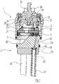
- Figur 1
- eine Axialschnitt durch die Steuerkartusche eines sanitären Einhebelmischventils mit darunter angeordnetem zweiteiligem Boden;
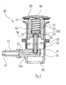
- Figur 2
- in einem gegenüber Figur 1 verkleinertem Maßstab einen Axialschnitt durch ein Ablaufventil, das von der Steuerkartusche der Figur 1 aus hydraulisch betätigt wird;
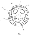
- Figur 3
- in vergrößertem Maßstab die Unteransicht der beweglichen Steuerscheibe der Steuerkartusche von Figur 1;
- Figur 4
- die Draufsicht auf die feststehende Grundscheibe der Steuerkartusche von Figur 1;
- Figur 5
- die Draufsicht auf den Boden der Steuerkartusche von Figur 1;
- Figur 6
- die Unteransicht des in Figur 5 dargestellten Kartuschenbodens;
- Figur 7
- die Draufsicht auf das obere Bodenteil, welches sich in Figur 1 unterhalb der Steuerkartusche befindet.
Der Sinn der beiden Nuten 29, 30 wird weiter unten deutlich werden.
Claims (7)
- Sanitäreinrichtung mitdadurch gekennzeichnet, daßa) einer Mischarmatur, die ihrerseits aufweist:aa) ein Gehäuse, das einen Zulauf für kaltes Wasser, einen Zulauf für warmes Wasser und einen Auslauf für Mischwasser umfaßt;ab) ein in dem Gehäuse angeordnetes, von Hand betätigbares Ventilelement, welches durch Bewegung in unterschiedlichen Richtungen den Fluß von Kalt- und/oder Warmwasser in einstellbarer Weise freigibt;b) einer Peripherieeinrichtung, welche über eine wasserführende Hydraulikleitung mit der Mischarmatur verbunden und von dieser aus betätigbar ist;c) einem in dem Gehäuse der Mischarmatur angeordneten Umstellelement, welches in einer ersten Stellung eine Verbindung zwischen einem Wasserzulauf und der Hydraulikleitung und in einer zweiten Stellung eine Verbindung zwischen dem Auslauf und der Hydraulikleitung herstellt,d) das Ventilelement (27) gleichzeitig als Umstellelement dient und in denjenigem Bereich seiner möglichen Positionen, in denen es die normale Funktion einer Mischarmatur erfüllt, eine Kommunikation der Hydraulikleitung (47) sowohl mit dem Zulauf (55) als auch mit dem Auslauf (39, 40) unterbindet.
- Sanitäreinrichtung nach Anspruch 1, dadurch gekennzeichnet, daß die beiden Stellungen des Ventilelements (27), in denen dieses eine Verbindung zu der Hydraulikleitung (47) herstellt, durch Bewegen des Ventilelements (27) in einer Richtung, die einer Veränderung der Temperatur des auslaufenden Mischwassers entspricht, erreichbar sind.
- Sanitäreinrichtung nach Anspruch 1 oder 2, dadurch gekennzeichnet, daß die beiden Stellungen des Ventilelements (27) durch eine Bewegung des Ventilelements (27) erreichbar sind, die eine Bewegung in Schließrichtung beinhaltet.
- Sanitäreinrichtung nach Anspruch 3, dadurch gekennzeichnet, daß die beiden Stellungen des Ventilelements (27) durch eine Bewegung des Ventilelements (27) erreichbar sind, die eine Bewegung in Schließrichtung über die Schließposition hinaus beinhaltet.
- Sanitäreinrichtung nach einem der Ansprüche 2 bis 4,
dadurch gekennzeichnet, daß eine Einrichtung vorgesehen ist, welche an der Grenze des normalen Bewegungsbereichs des Ventilelements (27) einen überwindbaren Widerstand erzeugt. - Sanitäreinrichtung nach einem der vorhergehenden Ansprüche, dadurch gekennzeichnet, daßa) das bewegliche Ventilelement (27) eine ebene Steuerscheibe ist, die eine Ausnehmung (31) aufweist, welche zumindest teilweise einen Wasserumlenkkanal bildet;b) eine mit der Steuerscheibe (27) zusammenwirkende, feststehende ebene Grundscheibe (21) vorgesehen ist, welche eine Durchtrittsöffnung (22) für Kaltwasser, eine Durchtrittsöffnung (23) für Warmwasser, eine Durchtrittsöffnung (24) für Mischwasser und zwei mit der Hydraulikleitung (47) kommunizierende Durchgangsbohrungen (25, 26) aufweist,
wobeic) die Steuerscheibe (27) in ihrer an der Grundscheibe (21) anliegenden Fläche eine erste Nut (29) aufweist, welche in einer ersten Stellung der Steuerscheibe (27) eine Verbindung zwischen der einen (25) der beiden Durchgangsbohrungen (25, 26) der Grundscheibe (21) mit der Durchtrittsöffnung (22) für Kaltwasser oder der Durchtrittsöffnung (23) für Warmwasser herstellt, und in dieser Fläche eine zweite Nut (30) aufweist, welche in einer zweiten Stellung der Steuerscheibe (27) eine Verbindung zwischen der zweiten (26) der beiden Durchgangsbohrungen (25, 26) der Grundscheibe (21) mit der Durchtrittsöffnung (24) für Mischwasser herstellt. - Sanitäreinrichtung nach Anspruch 6, dadurch gekennzeichnet, daß die Steuerscheibe (27) und die Grundscheibe (21) in einem Kartuschengehäuse (3) angeordnet sind, das nach unten durch einen Kartuschenboden (4) abgeschlossen ist, der ebenfalls eine Durchtrittsöffnung (5) für Kaltwasser, eine Durchtrittsöffnung (6) für Warmwasser, eine Durchtrittsöffnung (7) für Mischwasser und zwei Durchgangsbohrungen (8, 9), welche mit der Hydraulikleitung (47) kommunizieren, aufweist, und daß auf der äußeren Stirnfläche des Kartuschenbodens (4) ein Kanal (18) eingearbeitet ist, welcher die beiden Durchgangsbohrungen (8, 9) miteinander verbindet.
Applications Claiming Priority (2)
| Application Number | Priority Date | Filing Date | Title |
|---|---|---|---|
| DE10149516A DE10149516C1 (de) | 2001-10-08 | 2001-10-08 | Sanitäreinrichtung |
| DE10149516 | 2001-10-08 |
Publications (3)
| Publication Number | Publication Date |
|---|---|
| EP1300618A2 true EP1300618A2 (de) | 2003-04-09 |
| EP1300618A3 EP1300618A3 (de) | 2003-12-17 |
| EP1300618B1 EP1300618B1 (de) | 2005-03-16 |
Family
ID=7701755
Family Applications (1)
| Application Number | Title | Priority Date | Filing Date |
|---|---|---|---|
| EP02020737A Expired - Lifetime EP1300618B1 (de) | 2001-10-08 | 2002-09-16 | Sanitäreinrichtung |
Country Status (3)
| Country | Link |
|---|---|
| EP (1) | EP1300618B1 (de) |
| AT (1) | ATE291189T1 (de) |
| DE (2) | DE10149516C1 (de) |
Citations (1)
| Publication number | Priority date | Publication date | Assignee | Title |
|---|---|---|---|---|
| DE1156713B (de) | 1959-07-15 | 1963-10-31 | Fritz W Post | Mischbatterie mit Eingriffbedienung fuer sanitaere Objekte |
Family Cites Families (6)
| Publication number | Priority date | Publication date | Assignee | Title |
|---|---|---|---|---|
| GB1430234A (en) * | 1972-05-05 | 1976-03-31 | Imi Opella Ltd | Fluid control tap and plug assembly |
| DE2526949A1 (de) * | 1975-03-18 | 1976-09-30 | Ifoe Ab Loensboda | Mischventil |
| DE19523884A1 (de) * | 1995-06-30 | 1997-01-02 | Grohe Armaturen Friedrich | Mischbatterie |
| DE19640509A1 (de) * | 1996-10-01 | 1998-04-02 | Grohe Kg Hans | Sanitärarmatur |
| FR2760812B1 (fr) * | 1997-03-14 | 1999-06-04 | Norton Desmarquest Fine Cerami | Disques pour cartouche de mitigeur a ecoulements separes et cartouche les comportant |
| DE19904705B4 (de) * | 1999-02-05 | 2007-04-12 | Grohe Ag | Ventil |
-
2001
- 2001-10-08 DE DE10149516A patent/DE10149516C1/de not_active Expired - Fee Related
-
2002
- 2002-09-16 DE DE50202466T patent/DE50202466D1/de not_active Expired - Lifetime
- 2002-09-16 AT AT02020737T patent/ATE291189T1/de active
- 2002-09-16 EP EP02020737A patent/EP1300618B1/de not_active Expired - Lifetime
Patent Citations (1)
| Publication number | Priority date | Publication date | Assignee | Title |
|---|---|---|---|---|
| DE1156713B (de) | 1959-07-15 | 1963-10-31 | Fritz W Post | Mischbatterie mit Eingriffbedienung fuer sanitaere Objekte |
Also Published As
| Publication number | Publication date |
|---|---|
| ATE291189T1 (de) | 2005-04-15 |
| DE10149516C1 (de) | 2003-02-20 |
| EP1300618B1 (de) | 2005-03-16 |
| EP1300618A3 (de) | 2003-12-17 |
| DE50202466D1 (de) | 2005-04-21 |
Similar Documents
| Publication | Publication Date | Title |
|---|---|---|
| DE3202040C2 (de) | ||
| DE883082C (de) | Tastervorrichtung fuer eine Kopierfraesmaschine | |
| DE3612988A1 (de) | Mischbatterie | |
| DE68914166T2 (de) | Thermostatisches Mischventil. | |
| DE102006040558B4 (de) | Ventileinrichtung für Sanitätarmatur und Sanitärarmatur | |
| EP1576307B1 (de) | Sanitäre auslaufarmatur | |
| EP0834691A2 (de) | Sanitärarmatur | |
| EP1794377B1 (de) | Sanitäre unterputzarmatur | |
| CH661577A5 (de) | Sanitaerarmatur. | |
| DE3525053A1 (de) | Sanitaeres ventil | |
| DE2804803A1 (de) | Thermostatventil | |
| DE3113653A1 (de) | Mischbatterie | |
| DE10149516C1 (de) | Sanitäreinrichtung | |
| DE2442482A1 (de) | Ventilanordnung zum steuern des wasserzulaufs zu einer oder mehreren wasserabgabestellen | |
| DE2543112C3 (de) | Mischarmatur für sanitäre Anlagen o.dgl. | |
| DE2907565C2 (de) | Kombinierte Selbstschluß- und Mischarmatur | |
| DE1550412A1 (de) | Mischventil | |
| DE102005040159B3 (de) | Sanitäre Auslaufarmatur, insbesondere Einhebelmischer | |
| DE3243268A1 (de) | Wassermischhahn | |
| EP1809822A1 (de) | Sanitäre unterputzarmatur | |
| CH660219A5 (de) | Einhebelmischventil. | |
| DE551977C (de) | Mischventil fuer Kalt- und Warmwasser | |
| WO2004059094A1 (de) | Sanitäre auslaufarmatur | |
| WO2009135326A1 (de) | Handbrause mit einem an einem handgriff angeordneten brausekopf | |
| DE2231702A1 (de) | Fluessigkeitshahn |
Legal Events
| Date | Code | Title | Description |
|---|---|---|---|
| PUAI | Public reference made under article 153(3) epc to a published international application that has entered the european phase |
Free format text: ORIGINAL CODE: 0009012 |
|
| AK | Designated contracting states |
Kind code of ref document: A2 Designated state(s): AT BE BG CH CY CZ DE DK EE ES FI FR GB GR IE IT LI LU MC NL PT SE SK TR |
|
| AX | Request for extension of the european patent |
Extension state: AL LT LV MK RO SI |
|
| PUAL | Search report despatched |
Free format text: ORIGINAL CODE: 0009013 |
|
| AK | Designated contracting states |
Kind code of ref document: A3 Designated state(s): AT BE BG CH CY CZ DE DK EE ES FI FR GB GR IE IT LI LU MC NL PT SE SK TR |
|
| AX | Request for extension of the european patent |
Extension state: AL LT LV MK RO SI |
|
| RIC1 | Information provided on ipc code assigned before grant |
Ipc: 7E 03C 1/22 B Ipc: 7E 03C 1/04 B Ipc: 7F 16K 11/078 A Ipc: 7F 16K 1/12 B Ipc: 7F 16K 31/62 B |
|
| GRAP | Despatch of communication of intention to grant a patent |
Free format text: ORIGINAL CODE: EPIDOSNIGR1 |
|
| 17P | Request for examination filed |
Effective date: 20040503 |
|
| AKX | Designation fees paid |
Designated state(s): AT CH DE FR LI NL |
|
| GRAS | Grant fee paid |
Free format text: ORIGINAL CODE: EPIDOSNIGR3 |
|
| GRAA | (expected) grant |
Free format text: ORIGINAL CODE: 0009210 |
|
| AK | Designated contracting states |
Kind code of ref document: B1 Designated state(s): AT CH DE FR LI NL |
|
| REG | Reference to a national code |
Ref country code: CH Ref legal event code: EP |
|
| REG | Reference to a national code |
Ref country code: IE Ref legal event code: FG4D Free format text: GERMAN |
|
| REF | Corresponds to: |
Ref document number: 50202466 Country of ref document: DE Date of ref document: 20050421 Kind code of ref document: P |
|
| REG | Reference to a national code |
Ref country code: CH Ref legal event code: NV Representative=s name: FREI PATENTANWALTSBUERO |
|
| PLBE | No opposition filed within time limit |
Free format text: ORIGINAL CODE: 0009261 |
|
| STAA | Information on the status of an ep patent application or granted ep patent |
Free format text: STATUS: NO OPPOSITION FILED WITHIN TIME LIMIT |
|
| 26N | No opposition filed |
Effective date: 20051219 |
|
| ET | Fr: translation filed | ||
| PGFP | Annual fee paid to national office [announced via postgrant information from national office to epo] |
Ref country code: DE Payment date: 20101126 Year of fee payment: 9 |
|
| PGFP | Annual fee paid to national office [announced via postgrant information from national office to epo] |
Ref country code: CH Payment date: 20110923 Year of fee payment: 10 |
|
| PGFP | Annual fee paid to national office [announced via postgrant information from national office to epo] |
Ref country code: FR Payment date: 20111003 Year of fee payment: 10 Ref country code: AT Payment date: 20110926 Year of fee payment: 10 |
|
| PGFP | Annual fee paid to national office [announced via postgrant information from national office to epo] |
Ref country code: NL Payment date: 20110927 Year of fee payment: 10 |
|
| REG | Reference to a national code |
Ref country code: NL Ref legal event code: V1 Effective date: 20130401 |
|
| REG | Reference to a national code |
Ref country code: CH Ref legal event code: PL |
|
| REG | Reference to a national code |
Ref country code: AT Ref legal event code: MM01 Ref document number: 291189 Country of ref document: AT Kind code of ref document: T Effective date: 20120916 |
|
| REG | Reference to a national code |
Ref country code: FR Ref legal event code: ST Effective date: 20130531 |
|
| PG25 | Lapsed in a contracting state [announced via postgrant information from national office to epo] |
Ref country code: CH Free format text: LAPSE BECAUSE OF NON-PAYMENT OF DUE FEES Effective date: 20120930 Ref country code: LI Free format text: LAPSE BECAUSE OF NON-PAYMENT OF DUE FEES Effective date: 20120930 Ref country code: DE Free format text: LAPSE BECAUSE OF NON-PAYMENT OF DUE FEES Effective date: 20130403 Ref country code: AT Free format text: LAPSE BECAUSE OF NON-PAYMENT OF DUE FEES Effective date: 20120916 |
|
| PG25 | Lapsed in a contracting state [announced via postgrant information from national office to epo] |
Ref country code: FR Free format text: LAPSE BECAUSE OF NON-PAYMENT OF DUE FEES Effective date: 20121001 Ref country code: NL Free format text: LAPSE BECAUSE OF NON-PAYMENT OF DUE FEES Effective date: 20130401 |
|
| REG | Reference to a national code |
Ref country code: DE Ref legal event code: R119 Ref document number: 50202466 Country of ref document: DE Effective date: 20130403 |