EP1300618B1 - Dispositif sanitaire - Google Patents
Dispositif sanitaire Download PDFInfo
- Publication number
- EP1300618B1 EP1300618B1 EP02020737A EP02020737A EP1300618B1 EP 1300618 B1 EP1300618 B1 EP 1300618B1 EP 02020737 A EP02020737 A EP 02020737A EP 02020737 A EP02020737 A EP 02020737A EP 1300618 B1 EP1300618 B1 EP 1300618B1
- Authority
- EP
- European Patent Office
- Prior art keywords
- water
- valve element
- opening
- hydraulic line
- cartridge
- Prior art date
- Legal status (The legal status is an assumption and is not a legal conclusion. Google has not performed a legal analysis and makes no representation as to the accuracy of the status listed.)
- Expired - Lifetime
Links
- XLYOFNOQVPJJNP-UHFFFAOYSA-N water Substances O XLYOFNOQVPJJNP-UHFFFAOYSA-N 0.000 claims abstract description 59
- 230000002093 peripheral effect Effects 0.000 claims description 18
- 230000008859 change Effects 0.000 claims description 5
- 230000006835 compression Effects 0.000 description 5
- 238000007906 compression Methods 0.000 description 5
- 238000010276 construction Methods 0.000 description 4
- 238000007789 sealing Methods 0.000 description 4
- 238000004891 communication Methods 0.000 description 2
- 239000002131 composite material Substances 0.000 description 2
- 238000012986 modification Methods 0.000 description 2
- 230000004048 modification Effects 0.000 description 2
- 230000004308 accommodation Effects 0.000 description 1
- 230000009471 action Effects 0.000 description 1
- 239000000919 ceramic Substances 0.000 description 1
- 229910010293 ceramic material Inorganic materials 0.000 description 1
- 238000005516 engineering process Methods 0.000 description 1
- 238000011010 flushing procedure Methods 0.000 description 1
- 230000003993 interaction Effects 0.000 description 1
- 238000004519 manufacturing process Methods 0.000 description 1
- 239000002184 metal Substances 0.000 description 1
- 239000000203 mixture Substances 0.000 description 1
- 230000000284 resting effect Effects 0.000 description 1
- 238000005406 washing Methods 0.000 description 1
Images
Classifications
-
- F—MECHANICAL ENGINEERING; LIGHTING; HEATING; WEAPONS; BLASTING
- F16—ENGINEERING ELEMENTS AND UNITS; GENERAL MEASURES FOR PRODUCING AND MAINTAINING EFFECTIVE FUNCTIONING OF MACHINES OR INSTALLATIONS; THERMAL INSULATION IN GENERAL
- F16K—VALVES; TAPS; COCKS; ACTUATING-FLOATS; DEVICES FOR VENTING OR AERATING
- F16K31/00—Actuating devices; Operating means; Releasing devices
- F16K31/12—Actuating devices; Operating means; Releasing devices actuated by fluid
-
- F—MECHANICAL ENGINEERING; LIGHTING; HEATING; WEAPONS; BLASTING
- F16—ENGINEERING ELEMENTS AND UNITS; GENERAL MEASURES FOR PRODUCING AND MAINTAINING EFFECTIVE FUNCTIONING OF MACHINES OR INSTALLATIONS; THERMAL INSULATION IN GENERAL
- F16K—VALVES; TAPS; COCKS; ACTUATING-FLOATS; DEVICES FOR VENTING OR AERATING
- F16K11/00—Multiple-way valves, e.g. mixing valves; Pipe fittings incorporating such valves
- F16K11/02—Multiple-way valves, e.g. mixing valves; Pipe fittings incorporating such valves with all movable sealing faces moving as one unit
- F16K11/06—Multiple-way valves, e.g. mixing valves; Pipe fittings incorporating such valves with all movable sealing faces moving as one unit comprising only sliding valves, i.e. sliding closure elements
- F16K11/078—Multiple-way valves, e.g. mixing valves; Pipe fittings incorporating such valves with all movable sealing faces moving as one unit comprising only sliding valves, i.e. sliding closure elements with pivoted and linearly movable closure members
- F16K11/0782—Single-lever operated mixing valves with closure members having flat sealing faces
-
- F—MECHANICAL ENGINEERING; LIGHTING; HEATING; WEAPONS; BLASTING
- F16—ENGINEERING ELEMENTS AND UNITS; GENERAL MEASURES FOR PRODUCING AND MAINTAINING EFFECTIVE FUNCTIONING OF MACHINES OR INSTALLATIONS; THERMAL INSULATION IN GENERAL
- F16K—VALVES; TAPS; COCKS; ACTUATING-FLOATS; DEVICES FOR VENTING OR AERATING
- F16K31/00—Actuating devices; Operating means; Releasing devices
- F16K31/44—Mechanical actuating means
- F16K31/62—Pedals or like operating members, e.g. actuated by knee or hip
Definitions
- peripherals Near sanitary mixer taps can be found in the bathroom often called "peripherals", which are moved back and forth between two positions have to.
- a prominent example of such a peripheral device is the outlet valve, which is on Floor of the vanity is located, where the mixer tap is mounted.
- Other examples of peripherals are device shut-off valves, which the water flow to a Flushing or washing machine release, the changeover device, which the water flow either to a shower or in releases a bathtub, and more.
- These peripherals are independent of the Hand-operated mixer tap. Increasingly, however, the Wish loud, the peripherals from the mixing faucet from serving, what the latter with the Peripheral device connected via a hydraulic line is.
- a sanitary device of the type mentioned is described in DE-AS 11 56 713.
- the hydraulic operated peripheral device is here a drain valve.
- the mixing valve serves as a hollow cylinder or hollow ball formed valve plug, the order a horizontal axis is pivotable. Through a groove in the lateral surface of this valve plug is always either a connection between the cold water inlet the mixing valve and the hydraulic line or the spout the mixing valve and the hydraulic line ago.
- the drain valve is only open as long as in the hydraulic line Water pressure is pending and closes automatically, when the water pressure is eliminated, for example by corresponding pivoting of the valve plug.
- the valve elements, which the setting of the leaking mixed water serve are obviously inside of the pivotable valve plug and are of this independently.
- This known sanitary device has several disadvantages On: On the one hand, the construction of the mixing valve is proportionate complicated; it is a completely independent one Construction, as the pivoting chick itself found in no other mixing valve in this way. By the juxtaposition of Umstellelement and the water flow determining valve element becomes a great variety needed by parts. Besides, it is not possible without impending water pressure the drain valve in the to hold open position.
- Object of the present invention is a sanitary device of the type mentioned above in such a way that they are cheaper overall and better with already existing constructions of mixing valves compatible is, so that existing structures only minor Changes must be made.
- valve element in that area of his positions, in which it is his "normal” function exercises a communication of the hydraulic line neither with the water inlet still with the outlet permits, changed the position of the movable part of the peripheral device during the "normal" operation of the sanitary fitting not: is the peripheral device not under pressure, Of course, their moving part remains in course this position. Is the peripheral device against it under pressure, this pressure can not be reduced, so that the movable part of the peripheral device also remains in the appropriate position.
- the two positions of the valve element in which this connects to the hydraulic line produced by movement of the valve element in one direction, that of a change in temperature the leaking mixed water corresponds, accessible are.
- the manual actuator the mixing valve so the control handle, to change the temperature is rotated about an approximately vertical axis.
- the two positions of the valve element achievable by a movement of the valve element are, which includes a movement in the closing direction.
- Finding the positions of the valve element, on which the peripheral device is actuated succeeds then especially easy. For example, the mixing valve first closed and then a pivoting the valve element in the direction of a temperature change be effected over the normal path of movement of the Valve element goes out.
- the swivel angle can be in this Trap also be relatively small.
- a device which is at the limit of the normal range of motion the valve element a conquerable resistance generated.
- the user can therefore at the noticeable resistance detect when he is adjusting the valve element leaves the "normal" functional area so that he does not accidentally gets into positions of the valve element, in which this actuates the peripheral device.
- control disk and the base disk arranged in a cartridge case, the bottom completed by a cartridge bottom, which also a passage opening for cold water, a passage opening for hot water, a passage opening for mixed water and two through holes, which communicate with the hydraulic line, wherein on the outer face of the cartridge bottom a channel is incorporated, which the two through holes connects with each other.
- the accommodation of control discs in so-called Steuerkartuschen is widespread, since the An error just occurs the entire control cartridge can be exchanged.
- the last described above Embodiment of the invention can be known from Create control cartridges very simply by that only the cartridge bottom also additional through holes which then gets on the outer cartridge surface be connected to each other. A connection of this Both through holes is advantageous because then the bottom of the outer fitting housing, which is the Control cartridge surrounds, only from a single bore needs to be pierced.
- the outer surface of the Cartridge bottom offers manufacturing technology and geometric reasons for such a connection at..
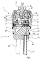
- the reference numeral 1 is a total of Control cartridge referred to in its basic Structure except as described in detail below Details are known.
- This tax carriage 1 is on a composite of two parts 2a, 2b dashboard floor 2 attached.
- the control cartridge 1 comprises a substantially rotationally symmetrical Cartridge housing 3 in which from below to the top of the following described components are housed:
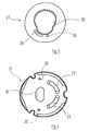
- the cartridge bottom 4, the closer in Figures 5 and 6 is shown in the lower, open end of the Cartridge housing 3 used.
- a larger passage opening 7 formed for mixed water are laterally from the mixed water passage opening 7, slightly below the horizontal equator line of the figure 5 and 6, through the cartridge bottom 4 also two small Through holes 8, 9 passed, the meaning will become clear later.
- the mouths of the Passage openings 5, 6, 7 in the illustrated in Figure 6 Bottom of the cartridge bottom 4 with seals 15, 16, 17 surround.
- the mouth openings of the through holes 8, 9, however, are over an arcuate passage openings 5, 6 encompassing channel 18 connected to each other.
- the channel 18 has in its center a in the space extending between the two passage openings 5, 6 Confiscation 19 on.
- the entire channel 18 including the mouth openings of the through holes 8, 9 is from another correspondingly shaped seal 20 surround.
- FIG. 4 On the above-described cartridge bottom 4 is immovable and a non-rotatable a flat base disk 21.
- the base plate 21 is made in a known manner of ceramic Material and is at its top on high Goodness polished.
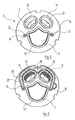
- FIG. 4 also the base disk 21 two through openings 22, 23rd for cold or hot water, taking the form of circular ring segments own, as well as a larger passage opening 24 for mixed water. Laterally from the passage opening 24 pierce the bottom plate 21 again two in diameter small through holes 25, 26, which with the through holes 8, 9 of the cartridge bottom. 4 aligned.
- a level Control disk 27 On the fixed base plate 21 is a level Control disk 27, which in a known manner against the Base disk 21 rotatory and translationally movable is.
- the movable control disk 27 is made of ceramic manufactured and pointing at her down, in Figure 3 shown and resting on the bottom plate 21 Surface polished to high quality.
- the movable control disk 27 is with a large passage opening 28th provided, their exact form in the present context is uninteresting and depending on the relative position the movable control disk 27, the passage openings 22, 23, 24 of the base disk 21 to varying degrees overlaps.
- end face of movable control disk 27 is also a circular arc Groove 29 formed. This is in the closed position the movable control disk 27 on the same Radius, relative to the axis of the base disk 21, on which is also the through holes 25, 26 of the base disk 21 are located.
- Another, in the questionable End face of the movable control disk 27 incorporated Groove 30 begins on the same radius on which the groove 29 is located, and opens to the passage opening 28. The meaning of the two grooves 29, 30 becomes clear below become.
- a plastic driving part 30th arranged, which with the movable control disk 27th is connected so that both parts together rotatory and are translationally displaceable.
- the driving part 30 has a downwardly opening recess 31, which the passage opening 28 of the movable control disk 27 completely covered, so that the passage opening 28 of the movable control disk 27 with the Recess 31 of the driving part 30 a Wasserumlenkund Mix room forms.
- One on the adjacent surfaces the movable control disk 27 and the driving part 30th inset seal 32 prevents between them Divide water in a lateral direction.
- a Mit Spotify 33 molded, in which the head 34th a shaft 35 positively engages.
- the society 35 is by means of a pivot pin 36 at a Guide member 37 pivotally mounted, which in turn the housing 3 of the cartridge closes up and stored in this rotatable about the axis of the housing 3 is.
- the guide part 37 overlaps with two parallel, planar guide surfaces 38, of which only one in the Figure 1 can be seen, two in the upper region of the driving part 30 trained parallel guide surfaces, the both are not visible in the drawing.
- the order is such that by pivoting the shaft 35 to the pivot pin 36 due to the action of the driving head 34 and the entrainment opening 33 that of the movable Control disc 27 and the driving part 30 formed unit linear between the guide surfaces 38 of the guide member 37 is performed while at a rotation of the control shaft 35 around the vertical axis of the control cartridge 1 the unit in question due to the interaction between the guide surfaces 28 of the guide member 37th and the adjacent guide surfaces of the driving part 30 is twisted around just this cartridge axis.
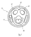
- the upper bottom part 2a of the fitting housing has a sloping channel 39, the mouth opening in the upper, shown in Figure 7 surface with the Passage opening 7 of the cartridge bottom 4 communicates.
- the channel 39 leads into a peripheral surface the bottom part 2a provided groove 40, the common with the bottom part 2a surrounding not shown Valve body limits an annulus, which in turn communicates with the spout of the sanitary fitting.
- the figure 7 shows, run through the upper Floor part 2a also two inlet channels 41, 42, whose Mouth points in the upper, shown in Figure 7 End face of the upper bottom part 2a with the passage openings 5, 6 communicate the cartridge bottom 4.
- the lower bottom part 2b is made of metal. It points two passages on, in the drawing not shown and with the inlet channels 41, 42nd of the upper floor part 2a communicate. In these passages of the lower bottom part 2b are inflow pipes Fortified 45 for cold and hot water, of which one shown in Figure 1. In another through hole 46 of the lower bottom part 2b, which in the lower Area configured as a threaded hole, is the end a hydraulic line 47 screwed, whose function will be clear below.
- the hydraulic line 47 leads to the drain valve of Vanity top to which the single lever mixer tap is attached is.
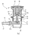
- This drain valve is in Figure 2 in axial section represented and designated overall by the reference numeral 50. It comprises a composite of two parts 51a, 51b Housing 51.
- the lower housing part 51a has a lateral connection 52 for the connecting pipe 47 on, from which a channel 53 to a centered in the interior the lower housing part 51a upwardly opening threaded hole 54 leads.
- the upper apron-like area 55 of the lower housing part 51a widens upwards a clamping flange 56 on which an annular sealing disc 58 lies.
- the upper housing part 51b is screwed in from above.
- the lower housing part 51 a is of the Bottom forth under Inclusion of the sealing washer 58 to the Washbasin introduced while the upper housing part 51b from above through the drain opening of the washbasin is screwed through until the bottom of the vanity clamped between the two flanges 55 and 57 is.
- a guide body 59 guided axially displaceable, on its peripheral surface Having recirculated water from the recesses.
- the Guide body 59 carries on its upper side in the Top view circular disk-shaped head 60, wherein between the head 60 and the guide body 59 a annular sealing disc 61 is braced.
- a nach top opening cylinder bore 62 is provided inside the guide body 59 .
- a piston 63 slidably, the Piston rod 64 through a bore 65 of smaller diameter sealed passed. That in Figure 2 lower end of the piston rod 64 is again sealed, in the threaded bore 54 of the lower housing part 51 a screwed.
- the piston rod 64 is axially of a Bore 66 interspersed, in the immediately below of the piston 63 lying by a plurality of radial directed bores 67 with the below the piston 63 lying part of the cylinder bore 62 communicates.
- a compression spring 68 clamped, which usually the guide body 59 and thus the head 60 upward in the dargestelle in Figure 2 open position suppressed.
- Outflow opening 69 is provided, which with a siphon in known way can be connected.
- the control cartridge 1 can be operated in the usual way: depending on the relative position between the movable control disk 27 and the base plate 21, which by means of the shaft 35 is set, flows more or less cold and / or Hot water through the control cartridge 1 and the channel 39 and the groove 40 of the upper bottom part 2a to the outlet the fitting.
- the user can now the relative position the movable control disk 27 relative to the base disk 21 left again to close the drain valve 50 has led. As the pressure in the below the piston 63 lying cylinder chamber 52 of the drain valve 50 is not can escape, the drain valve 50 remains in his Closed position. The user can now use the Use sanitary fitting as you wish and according to your needs Desired to take cold and / or hot water.
- the user wishes to reopen the drain valve 50, so he proceeds as follows: Again brings the user first the control cartridge 1 in the closed state. He then pivots the movable control disk 27th with the help of the shaft 35 in one direction, the is opposite to that which leads to a closing the drain valve 50 has led. He reaches for this Way a position of the movable control disk 27, at which the introduced on the underside of the groove 30th with the through hole 26 in the base disk 21st Aligns and ultimately over the already several times described flow path with the below the piston 63 of the drain valve 50 lying part of the cylinder chamber 62nd communicated.
- the control cartridge 1 is designed so that between the extreme swivel positions of the control disk 27, the normal operation of the control cartridge. 1 are assigned, and those two positions, in where the drain valve 50 is actuated, a resistor to overcome, for example, not one is illustrated locking device is formed.
Landscapes
- Engineering & Computer Science (AREA)
- General Engineering & Computer Science (AREA)
- Mechanical Engineering (AREA)
- Multiple-Way Valves (AREA)
- Infusion, Injection, And Reservoir Apparatuses (AREA)
- Bidet-Like Cleaning Device And Other Flush Toilet Accessories (AREA)
Claims (7)
- Dispositif sanitaire aveca) une robinetterie mélangeuse, qui présente elle-même :aa) un corps de robinetterie, qui comprend une arrivée d'eau froide, une arrivée d'eau chaude et une sortie d'eau mitigée ;bb) un obturateur disposé dans le corps, pouvant être actionné manuellement, qui par un déplacement dans des directions différentes libère d'une manière réglable le flux d'eau froide et/ou d'eau chaude ;b) un équipement périphérique, qui est relié à la robinetterie mélangeuse par l'intermédiaire d'une conduite hydraulique conduisant de l'eau et qui peut être actionné à partir de ladite robinetterie ;c) un élément de commutation disposé dans le corps de la robinetterie mélangeuse, qui réalise dans une première position une liaison entre une arrivée d'eau et la conduite hydraulique et dans une deuxième position une liaison entre la sortie et la conduite hydraulique,
caractérisé en ce qued) l'obturateur (27) est conçu de telle sorte qu'il sert en même temps d'élément de commutation et que, dans la plage de ses positions possibles dans lesquelles il assure le fonctionnement normal d'une robinetterie mélangeuse, il supprime la communication de la conduite hydraulique (47) tant avec l'arrivée (41, 42) qu'avec la sortie (39, 40). - Dispositif sanitaire selon la revendication 1, caractérisé en ce que les deux positions de l'obturateur (27) dans lesquelles ce dernier réalise une liaison vers la conduite hydraulique (47) peuvent être obtenues par un déplacement de l'obturateur (27) dans une direction qui correspond à une modification de la température de l'eau mitigée obtenue à la sortie.
- Dispositif sanitaire selon la revendication 1 ou 2, caractérisé en ce que les deux positions de l'obturateur (27) peuvent être obtenues par un mouvement de l'obturateur (27) qui inclut un mouvement dans la direction de fermeture.
- Dispositif sanitaire selon la revendication 3, caractérisé en ce que les deux positions de l'obturateur (27) peuvent être obtenues par un mouvement de l'obturateur (27) qui inclut un mouvement dans la direction de fermeture au-delà de la position fermée.
- Dispositif sanitaire selon l'une des revendications 2 à 4, caractérisé en ce qu'il est prévu un équipement qui produit, à la limite de la plage normale de déplacement de l'obturateur (27), une résistance pouvant être surmontée.
- Dispositif sanitaire selon l'une des revendications précédentes, caractérisé en ce quea) l'obturateur mobile (27) est un disque de commande plan, qui présente un évidement (31) qui forme au moins pour partie un canal de déviation d'eau ;b) il est prévu un disque de base plan (21) fixe, qui coopère avec le disque de commande (27) et qui présente une ouverture de passage (22) pour l'eau froide, une ouverture de passage (23) pour l'eau chaude, une ouverture de passage (24) pour l'eau mitigée et deux perçages traversants (25, 26) communiquant avec la conduite hydraulique (47),c) le disque de commande (27) présentant, dans sa face appliquée contre le disque de base (21), une première rainure (29) qui, dans une première position du disque de commande (27), réalise une liaison entre le premier (25) des deux perçages traversants (25, 26) du disque de base (21) et l'ouverture de passage (22) pour l'eau froide ou l'ouverture de passage (23) pour l'eau chaude, et présentant dans cette face une deuxième rainure (30) qui, dans une deuxième position du disque de commande (27), réalise une liaison entre le deuxième (26) des deux perçages traversants (25, 26) du disque de base (21) et l'ouverture de passage (24) pour l'eau mitigée.
- Dispositif sanitaire selon la revendication 6, caractérisé en ce que le disque de commande (27) et le disque de base (21) sont disposés dans un corps de cartouche (3), qui est fermé vers le bas par un fond de cartouche (4) qui présente lui aussi une ouverture de passage (5) pour l'eau froide, une ouverture de passage (6) pour l'eau chaude, une ouverture de passage (7) pour l'eau mitigée et deux perçages traversants (8, 9) qui communiquent avec la conduite hydraulique (47), et en ce qu'un canal (18) est ménagé sur la face frontale extérieure du fond de cartouche (4), canal qui relie entre eux les deux perçages traversants (8, 9).
Applications Claiming Priority (2)
| Application Number | Priority Date | Filing Date | Title |
|---|---|---|---|
| DE10149516A DE10149516C1 (de) | 2001-10-08 | 2001-10-08 | Sanitäreinrichtung |
| DE10149516 | 2001-10-08 |
Publications (3)
| Publication Number | Publication Date |
|---|---|
| EP1300618A2 EP1300618A2 (fr) | 2003-04-09 |
| EP1300618A3 EP1300618A3 (fr) | 2003-12-17 |
| EP1300618B1 true EP1300618B1 (fr) | 2005-03-16 |
Family
ID=7701755
Family Applications (1)
| Application Number | Title | Priority Date | Filing Date |
|---|---|---|---|
| EP02020737A Expired - Lifetime EP1300618B1 (fr) | 2001-10-08 | 2002-09-16 | Dispositif sanitaire |
Country Status (3)
| Country | Link |
|---|---|
| EP (1) | EP1300618B1 (fr) |
| AT (1) | ATE291189T1 (fr) |
| DE (2) | DE10149516C1 (fr) |
Family Cites Families (7)
| Publication number | Priority date | Publication date | Assignee | Title |
|---|---|---|---|---|
| DE1156713B (de) * | 1959-07-15 | 1963-10-31 | Fritz W Post | Mischbatterie mit Eingriffbedienung fuer sanitaere Objekte |
| GB1430234A (en) * | 1972-05-05 | 1976-03-31 | Imi Opella Ltd | Fluid control tap and plug assembly |
| DE2526949A1 (de) * | 1975-03-18 | 1976-09-30 | Ifoe Ab Loensboda | Mischventil |
| DE19523884A1 (de) * | 1995-06-30 | 1997-01-02 | Grohe Armaturen Friedrich | Mischbatterie |
| DE19640509A1 (de) * | 1996-10-01 | 1998-04-02 | Grohe Kg Hans | Sanitärarmatur |
| FR2760812B1 (fr) * | 1997-03-14 | 1999-06-04 | Norton Desmarquest Fine Cerami | Disques pour cartouche de mitigeur a ecoulements separes et cartouche les comportant |
| DE19904705B4 (de) * | 1999-02-05 | 2007-04-12 | Grohe Ag | Ventil |
-
2001
- 2001-10-08 DE DE10149516A patent/DE10149516C1/de not_active Expired - Fee Related
-
2002
- 2002-09-16 DE DE50202466T patent/DE50202466D1/de not_active Expired - Lifetime
- 2002-09-16 AT AT02020737T patent/ATE291189T1/de active
- 2002-09-16 EP EP02020737A patent/EP1300618B1/fr not_active Expired - Lifetime
Also Published As
| Publication number | Publication date |
|---|---|
| ATE291189T1 (de) | 2005-04-15 |
| DE10149516C1 (de) | 2003-02-20 |
| EP1300618A2 (fr) | 2003-04-09 |
| EP1300618A3 (fr) | 2003-12-17 |
| DE50202466D1 (de) | 2005-04-21 |
Similar Documents
| Publication | Publication Date | Title |
|---|---|---|
| DE60209666T2 (de) | Vierteldrehungsthermostatischekartusche mit konzentrischem Antrieb, mit keramischen Scheiben, und eine Mischbatterie die diese enthält | |
| DE68904490T2 (de) | Scheibenventil. | |
| DE69008826T2 (de) | Steuereinheit für Warm- und Kaltwassermischventil. | |
| DE2413420A1 (de) | Mischbatteriesystem | |
| EP1895211B1 (fr) | Dispositif de ventilation pour une armature sanitaire et armature sanitaire | |
| EP0732147A2 (fr) | Pomme de douche multifonction | |
| EP0811184B1 (fr) | Cartouche pour batterie de robinet melangeur avec regulation thermostatique de la temperature | |
| DE3612988A1 (de) | Mischbatterie | |
| DE1550060A1 (de) | Mischventil | |
| CH651119A5 (de) | Mischventil fuer sanitaere einhebel-mischbatterie. | |
| DE102004018277B4 (de) | Mischventil für eine einarmige, nur durch Drehen betätigbare Mischbatterie | |
| WO2022175196A1 (fr) | Soupape sanitaire | |
| EP1576307B1 (fr) | Robinetterie sanitaire d'ecoulement | |
| EP0834691A2 (fr) | Robinet sanitaire | |
| EP0653581B1 (fr) | Robinet mitigeur et d'arrêt | |
| DE3113653C2 (de) | Mischbatterie | |
| EP1300618B1 (fr) | Dispositif sanitaire | |
| AT393154B (de) | Zum vermischen von warmwasser und kaltwasser dienendes mischventil | |
| DE4431435A1 (de) | Einhebelmischventil | |
| DE2804803A1 (de) | Thermostatventil | |
| EP0277584B1 (fr) | Mitigeur | |
| EP1809822B1 (fr) | Robinetterie sanitaire encastree | |
| DE102005040159B3 (de) | Sanitäre Auslaufarmatur, insbesondere Einhebelmischer | |
| DE2907565C2 (de) | Kombinierte Selbstschluß- und Mischarmatur | |
| DE2737478A1 (de) | Einhebelmischbatterie |
Legal Events
| Date | Code | Title | Description |
|---|---|---|---|
| PUAI | Public reference made under article 153(3) epc to a published international application that has entered the european phase |
Free format text: ORIGINAL CODE: 0009012 |
|
| AK | Designated contracting states |
Kind code of ref document: A2 Designated state(s): AT BE BG CH CY CZ DE DK EE ES FI FR GB GR IE IT LI LU MC NL PT SE SK TR |
|
| AX | Request for extension of the european patent |
Extension state: AL LT LV MK RO SI |
|
| PUAL | Search report despatched |
Free format text: ORIGINAL CODE: 0009013 |
|
| AK | Designated contracting states |
Kind code of ref document: A3 Designated state(s): AT BE BG CH CY CZ DE DK EE ES FI FR GB GR IE IT LI LU MC NL PT SE SK TR |
|
| AX | Request for extension of the european patent |
Extension state: AL LT LV MK RO SI |
|
| RIC1 | Information provided on ipc code assigned before grant |
Ipc: 7E 03C 1/22 B Ipc: 7E 03C 1/04 B Ipc: 7F 16K 11/078 A Ipc: 7F 16K 1/12 B Ipc: 7F 16K 31/62 B |
|
| GRAP | Despatch of communication of intention to grant a patent |
Free format text: ORIGINAL CODE: EPIDOSNIGR1 |
|
| 17P | Request for examination filed |
Effective date: 20040503 |
|
| AKX | Designation fees paid |
Designated state(s): AT CH DE FR LI NL |
|
| GRAS | Grant fee paid |
Free format text: ORIGINAL CODE: EPIDOSNIGR3 |
|
| GRAA | (expected) grant |
Free format text: ORIGINAL CODE: 0009210 |
|
| AK | Designated contracting states |
Kind code of ref document: B1 Designated state(s): AT CH DE FR LI NL |
|
| REG | Reference to a national code |
Ref country code: CH Ref legal event code: EP |
|
| REG | Reference to a national code |
Ref country code: IE Ref legal event code: FG4D Free format text: GERMAN |
|
| REF | Corresponds to: |
Ref document number: 50202466 Country of ref document: DE Date of ref document: 20050421 Kind code of ref document: P |
|
| REG | Reference to a national code |
Ref country code: CH Ref legal event code: NV Representative=s name: FREI PATENTANWALTSBUERO |
|
| PLBE | No opposition filed within time limit |
Free format text: ORIGINAL CODE: 0009261 |
|
| STAA | Information on the status of an ep patent application or granted ep patent |
Free format text: STATUS: NO OPPOSITION FILED WITHIN TIME LIMIT |
|
| 26N | No opposition filed |
Effective date: 20051219 |
|
| ET | Fr: translation filed | ||
| PGFP | Annual fee paid to national office [announced via postgrant information from national office to epo] |
Ref country code: DE Payment date: 20101126 Year of fee payment: 9 |
|
| PGFP | Annual fee paid to national office [announced via postgrant information from national office to epo] |
Ref country code: CH Payment date: 20110923 Year of fee payment: 10 |
|
| PGFP | Annual fee paid to national office [announced via postgrant information from national office to epo] |
Ref country code: FR Payment date: 20111003 Year of fee payment: 10 Ref country code: AT Payment date: 20110926 Year of fee payment: 10 |
|
| PGFP | Annual fee paid to national office [announced via postgrant information from national office to epo] |
Ref country code: NL Payment date: 20110927 Year of fee payment: 10 |
|
| REG | Reference to a national code |
Ref country code: NL Ref legal event code: V1 Effective date: 20130401 |
|
| REG | Reference to a national code |
Ref country code: CH Ref legal event code: PL |
|
| REG | Reference to a national code |
Ref country code: AT Ref legal event code: MM01 Ref document number: 291189 Country of ref document: AT Kind code of ref document: T Effective date: 20120916 |
|
| REG | Reference to a national code |
Ref country code: FR Ref legal event code: ST Effective date: 20130531 |
|
| PG25 | Lapsed in a contracting state [announced via postgrant information from national office to epo] |
Ref country code: CH Free format text: LAPSE BECAUSE OF NON-PAYMENT OF DUE FEES Effective date: 20120930 Ref country code: LI Free format text: LAPSE BECAUSE OF NON-PAYMENT OF DUE FEES Effective date: 20120930 Ref country code: DE Free format text: LAPSE BECAUSE OF NON-PAYMENT OF DUE FEES Effective date: 20130403 Ref country code: AT Free format text: LAPSE BECAUSE OF NON-PAYMENT OF DUE FEES Effective date: 20120916 |
|
| PG25 | Lapsed in a contracting state [announced via postgrant information from national office to epo] |
Ref country code: FR Free format text: LAPSE BECAUSE OF NON-PAYMENT OF DUE FEES Effective date: 20121001 Ref country code: NL Free format text: LAPSE BECAUSE OF NON-PAYMENT OF DUE FEES Effective date: 20130401 |
|
| REG | Reference to a national code |
Ref country code: DE Ref legal event code: R119 Ref document number: 50202466 Country of ref document: DE Effective date: 20130403 |