EP1300635A2 - Geräuschdämpfende Einrichtung für die Ausseneinheit einer grossen Klimaanlage - Google Patents
Geräuschdämpfende Einrichtung für die Ausseneinheit einer grossen Klimaanlage Download PDFInfo
- Publication number
- EP1300635A2 EP1300635A2 EP02022121A EP02022121A EP1300635A2 EP 1300635 A2 EP1300635 A2 EP 1300635A2 EP 02022121 A EP02022121 A EP 02022121A EP 02022121 A EP02022121 A EP 02022121A EP 1300635 A2 EP1300635 A2 EP 1300635A2
- Authority
- EP
- European Patent Office
- Prior art keywords
- air conditioner
- outdoor unit
- noise
- reduction structure
- noise reduction
- Prior art date
- Legal status (The legal status is an assumption and is not a legal conclusion. Google has not performed a legal analysis and makes no representation as to the accuracy of the status listed.)
- Granted
Links
Images


Classifications
-
- F—MECHANICAL ENGINEERING; LIGHTING; HEATING; WEAPONS; BLASTING
- F24—HEATING; RANGES; VENTILATING
- F24F—AIR-CONDITIONING; AIR-HUMIDIFICATION; VENTILATION; USE OF AIR CURRENTS FOR SCREENING
- F24F1/00—Room units for air-conditioning, e.g. separate or self-contained units or units receiving primary air from a central station
- F24F1/06—Separate outdoor units, e.g. outdoor unit to be linked to a separate room comprising a compressor and a heat exchanger
- F24F1/46—Component arrangements in separate outdoor units
- F24F1/48—Component arrangements in separate outdoor units characterised by air airflow, e.g. inlet or outlet airflow
- F24F1/52—Component arrangements in separate outdoor units characterised by air airflow, e.g. inlet or outlet airflow with inlet and outlet arranged on the same side, e.g. for mounting in a wall opening
-
- F—MECHANICAL ENGINEERING; LIGHTING; HEATING; WEAPONS; BLASTING
- F24—HEATING; RANGES; VENTILATING
- F24F—AIR-CONDITIONING; AIR-HUMIDIFICATION; VENTILATION; USE OF AIR CURRENTS FOR SCREENING
- F24F1/00—Room units for air-conditioning, e.g. separate or self-contained units or units receiving primary air from a central station
- F24F1/06—Separate outdoor units, e.g. outdoor unit to be linked to a separate room comprising a compressor and a heat exchanger
- F24F1/08—Compressors specially adapted for separate outdoor units
- F24F1/12—Vibration or noise prevention thereof
-
- F—MECHANICAL ENGINEERING; LIGHTING; HEATING; WEAPONS; BLASTING
- F24—HEATING; RANGES; VENTILATING
- F24F—AIR-CONDITIONING; AIR-HUMIDIFICATION; VENTILATION; USE OF AIR CURRENTS FOR SCREENING
- F24F13/00—Details common to, or for air-conditioning, air-humidification, ventilation or use of air currents for screening
- F24F13/24—Means for preventing or suppressing noise
-
- F—MECHANICAL ENGINEERING; LIGHTING; HEATING; WEAPONS; BLASTING
- F04—POSITIVE - DISPLACEMENT MACHINES FOR LIQUIDS; PUMPS FOR LIQUIDS OR ELASTIC FLUIDS
- F04C—ROTARY-PISTON, OR OSCILLATING-PISTON, POSITIVE-DISPLACEMENT MACHINES FOR LIQUIDS; ROTARY-PISTON, OR OSCILLATING-PISTON, POSITIVE-DISPLACEMENT PUMPS
- F04C29/00—Component parts, details or accessories of pumps or pumping installations, not provided for in groups F04C18/00 - F04C28/00
- F04C29/06—Silencing
-
- F—MECHANICAL ENGINEERING; LIGHTING; HEATING; WEAPONS; BLASTING
- F24—HEATING; RANGES; VENTILATING
- F24F—AIR-CONDITIONING; AIR-HUMIDIFICATION; VENTILATION; USE OF AIR CURRENTS FOR SCREENING
- F24F13/00—Details common to, or for air-conditioning, air-humidification, ventilation or use of air currents for screening
- F24F13/24—Means for preventing or suppressing noise
- F24F2013/242—Sound-absorbing material
Definitions
- the present invention relates to an outdoor unit of a large-sized air conditioner provided with a constant-speed compressor and an inverter compressor installed therein, and more particularly to a noise reduction structure of the outdoor unit for the large-sized air conditioner in order to prevent noise generated from the inverter compressor from being transmitted to the outside.
- a large-sized air conditioner is an apparatus for maintaining a comfortable temperature, humidity, and the like of an indoor space.
- the large-sized air conditioner comprises an indoor unit and an outdoor unit.
- the indoor unit is arranged inside the room, and includes an indoor blower and an evaporator.
- the outdoor unit is arranged outside the room, and includes an outdoor blower, a condenser and a compressor.
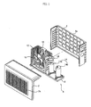
- Fig. 1 is an exploded perspective view of an outdoor unit of a conventional large-sized air conditioner.
- the outdoor unit of the conventional large-sized air conditioner comprises a case 8, an outdoor blast fan 10, a condenser 12, and a compression section 14.
- the case 8 comprises a front panel 2 provided with a heat discharging outlet 2a formed thereon, a back panel 4 provided with a heat absorbing inlet 4a formed thereon, and a base pan 6.
- the front and back panels 2 and 4 are arranged on the upper surface of the base pan 6.
- the outdoor blast fan 10 is installed inside the front panel 2 and serves to forcibly blow outdoor air.
- the condenser 12 is installed inside the back panel 4 and serves to exchange heat between the outdoor air forcibly-blown by the outdoor blast fan 10 and a refrigerant.
- the compression section 14 is arranged near the condenser 12 and serves to compress the refrigerant so as to control air-cooling capacity of the air conditioner, thereby circulating the refrigerant through a refrigerating cycle consisting of compression, condensation, expansion, and evaporation.
- the compression section 14 includes a constant-speed compressor 14a driven at constant speed, and an inverter compressor 14b driven at variable speed. Therefore, the compression section 14 changes its rotational speed according to the change of an input frequency and then controls flow rate of the refrigerant circulated through the refrigerant cycle, thereby variably changing the air-cooling capacity of the air conditioner.
- the rotational speed of the inverter compressor 14b is variably changed according to the air-cooling capacity change and then continuously driven, while the air conditioner operates. Only when a higher air-cooling capacity of the air conditioner is required, the constant-speed compressor 14a is driven.
- the inverter compressor 14b is rotated with a higher speed, thereby increasing the quantity of inflow and outflow of the refrigerant, and effectively controlling the air-cooling capacity of the air conditioner.
- a reference number 16 represents a motor mount fixedly installed on the condenser 12 so as to fix a motor for rotating the outdoor blast fan 10, and a reference number 18 represents a partition wall formed within the case 8, for dividing a space where the constant-speed and inverter compressors 14a and 14b are installed from a space where the condenser 12 is installed.
- the inverter compressor 14b is driven at a higher speed, thereby increasing the flow rate of the refrigerant circulated through the refrigerating cycle.
- the inverter compressor 14b when a signal requiring a much higher air-cooling capacity is inputted to the inverter compressor 14b, the inverter compressor 14b is overloaded. Then, the constant-speed compressor 14a as well as the inverter compressor 14a is driven, thereby further increasing the flow rate of the refrigerant circulated through the refrigerating cycle.
- the rotational speed of the inverter compressor 14b is variably changed according to the change of the input frequency, thereby generating noise due to the pulsation of pressure of the refrigerant and the structural vibration of the inverter compressor 64b.
- the inverter compressor 14b installed on the outdoor unit of the conventional large-sized air conditioner is not installed on a separate space in the manner of another inverter compressor installed on a refrigerator, but is installed on the space divided by the partition wall within the case 8. Therefore, the noise generated due to the driving of the inverter compressor 14b is easily transmitted to the outside.
- the present invention has been made in view of the above problems, and it is an object of the present invention to provide a noise reduction structure of an outdoor unit of a large-sized air conditioner so as to prevent noise generated by an inverter compressor installed on the outdoor unit of the air conditioner from being transmitted to the outside via a case of the outdoor unit.
- a noise reduction structure of an outdoor unit of a large-sized air conditioner comprising a compressor for compressing a refrigerant so as to circulate the refrigerant through a refrigerating cycle, wherein an anti-noise barrier provided with protrusions formed thereon surrounds the compressor so as to prevent noise generated from the compressor from being transmitted to the outside.
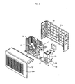
- Fig. 2 is an exploded perspective view of a noise reduction structure of an outdoor unit of a large-sized air conditioner in accordance with an embodiment of the present invention.
- Fig. 3 is a cross-sectional view taken along the line A-A of Fig. 2
- Fig. 4 is a cross-sectional view taken along the line B-B of Fig. 2.
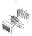
- Fig. 5 is an exploded perspective view of a noise reduction structure of an outdoor unit of a large-sized air conditioner in accordance with another embodiment of the present invention.
- Fig. 6 is a cross-sectional view taken along the line C-C of Fig. 5.
- the noise reduction structure of the outdoor unit of the large-sized air conditioner of the present invention comprises a case 58, an outdoor blast fan 60, a condenser 62, a constant-speed compressor 64a, an inverter compressor 64b, and an anti-noise barrier 70.
- the case 58 comprises a front panel 52 provided with a heat discharging outlet 52a formed thereon, a back panel 54 provided with a heat absorbing inlet 54a formed thereon, and a base pan 56.
- the front and back panels 52 and 54 are arranged on the upper surface of the base pan 56.
- the outdoor blast fan 60 is installed inside the front panel 52 and serves to forcibly blow outdoor air.
- the condenser 62 is installed inside the back panel 54 and serves to exchange heat between the outdoor air forcibly blown by the outdoor blast fan 60 and a refrigerant.
- the constant-speed compressor 64a and the inverter compressor 64b are arranged near the condenser 62.
- the constant-speed compressor 64a is driven at constant speed and the inverter compressor 64b is driven at variable speed so as to compress the refrigerant and to control the flow rate of the refrigerant circulated through the refrigerating cycle according to the air-cooling capacity change.
- the anti-noise barrier 70 surrounds the inverter compressor 64b and is provided with a plurality of protrusions 72 or 74, thereby preventing noise generated from the inverter compressor 64b from being transmitted to the outside.
- the noise reduction structure of the outdoor unit of the large-sized air conditioner of the present invention further comprises a sound absorbing and insulating material (not shown) surrounding the constant-speed compressor 64a.
- the sound absorbing and insulating material is formed by stacking a sound-absorbing material (not shown) made of porous material such as non-woven fabric or foam aerosol, and a sound-insulating material (not shown) made of rubber or metal.
- the inverter compressor 64b changes its rotational speed depending on the air-cooling capacity and then is continuously driven while the air conditioner operates.
- the constant-speed inverter 64a as well as the inverter compressor 64b is driven.
- the rotational speed of the inverter compressor 64b is variably changed according to an input frequency, thereby generating comparatively much noise due to the pulsation of pressure of the refrigerant and the structural vibration of the inverter compressor 64b.
- noise generation characteristics of the inverter compressor 64b are determined.
- the protrusions 72 or 74 are formed on one outer side surface of the anti-noise barrier 70 at a position where the noise is most strongly generated.
- the noise generated from the inverter compressor 64b surrounded with the anti-noise barrier 70 is transmitted in the form of sound waves, the noise is not vertically incident on the anti-noise barrier 70 but is reflected into the inside of the anti-noise barrier 70 by the protrusions 72 and 74 formed on the outer side surface of the anti-noise barrier 70.
- a sound absorbing and insulating material 76 for absorbing the noise generated from the inverter compressor 64b is formed on the inner wall of the anti-noise barrier 70.
- the sound absorbing and insulating material 76 is formed on the whole inner wall of the anti-noise barrier 70 except for the area of the protrusions 72 and 74.
- the sound absorbing and insulating material 76 includes a sound-absorbing material 76a and a sound-insulating material 76b.
- the sound-absorbing material 76a is made of a porous material such as felt, fabric, or foam aerosol in which an air volume is very large relative to its total volume.
- the sound-insulating material 76b is made of rubber or metal and stacked on the sound-absorbing material 76a.
- each of the protrusions 72 formed on one outer side surface of the anti-noise barrier 70 is horizontally extended and has a semi-circular cross section.
- the protrusions 72 formed on the anti-noise barrier 70 are parallelly spaced from each other by a designated distance (h).
- each of other protrusions 74 formed on one outer side surface of the anti-noise barrier 70 is horizontally extended and has an arc-shaped cross section.
- the protrusions 74 formed on the anti-noise barrier 70 are parallelly spaced from each other by a designated distance (h).
- a ventilation hole 74a is formed on the bottom of the protrusions 74 of Fig. 6, thereby emitting heat generated from the inverter compressor 64b to the outside.
- the top surface of the anti-noise barrier 70 is opened and the outdoor blast fan 60 is installed on the upper surface of the inverter compressor 64b, thereby effectively emitting the heat generated from the inverter compressor 64b to the outside.
- the inverter compressor 64b When power is applied, the inverter compressor 64b is driven. Since the rotational speed of the inverter compressor 64b is variably changed according to the air-cooling capacity change, the inverter compressor 64b controls the flow rate of the refrigerant circulated through the refrigerating cycle. As a result, noise is generated from the inverter compressor 64b.
- the noise generated from the inverter compressor 64b is partially absorbed or reduced by the sound absorbing and insulating material 76, and cut off from the outside by the anti-noise barrier 70 surrounding the inverter compressor 64b.
- the noise generated from the inverter compressor 64b is not vertically incident on the anti-noise barrier 70 but is obliquely incident on the anti-noise barrier 70 by the protrusions 72 and 74, the noise is then reflected into the inside of the anti-noise barrier 70, thereby not being transmitted to the outside.
- the heat generated from the inverter compressor 64b is emitted to the outside via the ventilation holes 74a formed on the protrusions 74 of the anti-noise barrier 70.
- the present invention provides a noise reduction structure of an outdoor unit of a large-sized air conditioner, in which an anti-noise barrier provided with protrusions formed thereon surrounds an inverter compressor, thereby preventing noise generated from the inverter compressor from being transmitted to the outside. Therefore, the noise generated from the inverter compressor is reflected into the inside of the anti-noise barrier by the protrusions, thereby reducing noise pollution and increasing performance of the air conditioner product.
Landscapes
- Engineering & Computer Science (AREA)
- Chemical & Material Sciences (AREA)
- Combustion & Propulsion (AREA)
- Mechanical Engineering (AREA)
- General Engineering & Computer Science (AREA)
- Compressor (AREA)
- Other Air-Conditioning Systems (AREA)
- Control Of Positive-Displacement Pumps (AREA)
Applications Claiming Priority (2)
| Application Number | Priority Date | Filing Date | Title |
|---|---|---|---|
| KR2001061460 | 2001-10-05 | ||
| KR10-2001-0061460A KR100420520B1 (ko) | 2001-10-05 | 2001-10-05 | 대형 공기조화기의 실외기용 소음저감구조 |
Publications (3)
| Publication Number | Publication Date |
|---|---|
| EP1300635A2 true EP1300635A2 (de) | 2003-04-09 |
| EP1300635A3 EP1300635A3 (de) | 2006-11-02 |
| EP1300635B1 EP1300635B1 (de) | 2009-09-09 |
Family
ID=19714900
Family Applications (1)
| Application Number | Title | Priority Date | Filing Date |
|---|---|---|---|
| EP02022121A Expired - Lifetime EP1300635B1 (de) | 2001-10-05 | 2002-10-02 | Geräuschdämpfende Einrichtung für die Ausseneinheit einer grossen Klimaanlage |
Country Status (5)
| Country | Link |
|---|---|
| EP (1) | EP1300635B1 (de) |
| JP (1) | JP3723537B2 (de) |
| KR (1) | KR100420520B1 (de) |
| CN (1) | CN1211615C (de) |
| DE (1) | DE60233626D1 (de) |
Cited By (7)
| Publication number | Priority date | Publication date | Assignee | Title |
|---|---|---|---|---|
| FR2879797A1 (fr) * | 2004-12-20 | 2006-06-23 | Valeo Climatisation Sa | Dispositif d'attenuation acoustique d'une installation de traitement d'un flux d'air, agence en grille a aubes |
| FR2909164A1 (fr) * | 2006-11-27 | 2008-05-30 | Harmonie Express Sarl | Dispositif conforme de maniere a pouvoir recouvrir des climatiseurs et sur la surface externe duquel peuvent figurer au moins une denomination et/ou au moins un signe figuratif. |
| WO2013134843A1 (pt) * | 2012-03-15 | 2013-09-19 | Electrolux Do Brasil S.A. | Aparelho condicionador de ar com amortecedor de vibrações |
| EP2472191A3 (de) * | 2010-12-29 | 2014-10-01 | LG Electronics Inc. | Außenraumeinheit für Klimaanlage |
| US20150033785A1 (en) * | 2012-03-20 | 2015-02-05 | Coway Co., Ltd. | Compressor noise suppressing structure and dehumidifier having the same |
| CN105698283A (zh) * | 2015-12-25 | 2016-06-22 | 广东美的制冷设备有限公司 | 压缩机组件、室外机及空调器 |
| CN114877420A (zh) * | 2022-05-24 | 2022-08-09 | 湖南中合科技有限公司 | 一种智能控制独立式中央空调 |
Families Citing this family (15)
| Publication number | Priority date | Publication date | Assignee | Title |
|---|---|---|---|---|
| KR20070039718A (ko) * | 2005-10-10 | 2007-04-13 | 위니아만도 주식회사 | 에어컨의 실외기 패널 구조 |
| KR100765570B1 (ko) * | 2006-02-08 | 2007-10-09 | 엘지전자 주식회사 | 공기조화기의 실외기 |
| CN100436957C (zh) * | 2006-08-16 | 2008-11-26 | 广东科龙电器股份有限公司 | 一种减小运行噪声的静音室外机 |
| CN102384571A (zh) * | 2011-09-29 | 2012-03-21 | Tcl空调器(武汉)有限公司 | 一种空调压缩机消声结构 |
| CN102721165A (zh) * | 2012-07-12 | 2012-10-10 | 王桂林 | 低噪音高效率移动式空调器 |
| CN104748252A (zh) * | 2013-12-25 | 2015-07-01 | 珠海格力电器股份有限公司 | 一种压缩机隔音装置、空调室外机和空调 |
| CN105020140A (zh) * | 2014-04-30 | 2015-11-04 | 杨永坚 | 一种真空压力复合泵泵体 |
| CN104048367A (zh) * | 2014-06-30 | 2014-09-17 | 珠海格力电器股份有限公司 | 压缩机减振降噪装置 |
| WO2017094198A1 (ja) * | 2015-12-04 | 2017-06-08 | 三菱電機株式会社 | 室外機 |
| CN105423445B (zh) * | 2015-12-25 | 2018-07-03 | 广东美的制冷设备有限公司 | 压缩机组件、室外机及空调器 |
| CN106765677A (zh) * | 2016-12-27 | 2017-05-31 | 珠海格力电器股份有限公司 | 一种空调室外机降噪结构及空调室外机 |
| CN109028349B (zh) * | 2018-06-15 | 2021-08-24 | 青岛海信日立空调系统有限公司 | 隔音罩、空调室外机以及降噪方法 |
| CN111656013A (zh) * | 2018-11-21 | 2020-09-11 | Nok株式会社 | 降噪结构 |
| JP7019097B2 (ja) * | 2019-04-03 | 2022-02-14 | 三菱電機株式会社 | 空気調和機の室外機 |
| CN113494771A (zh) * | 2021-06-30 | 2021-10-12 | 杭州金泰环境科技有限公司 | 一种降噪隔音效果好的大型空调机房系统 |
Family Cites Families (8)
| Publication number | Priority date | Publication date | Assignee | Title |
|---|---|---|---|---|
| JPH0267823U (de) * | 1988-07-27 | 1990-05-23 | ||
| US5151018A (en) * | 1990-07-31 | 1992-09-29 | Copeland Corporation | Sound attenuation chamber |
| JPH0836389A (ja) * | 1994-07-21 | 1996-02-06 | Sharp Corp | 圧縮機の取付装置 |
| JP2943676B2 (ja) * | 1995-11-24 | 1999-08-30 | 三菱電機株式会社 | 冷蔵庫 |
| JPH10148362A (ja) * | 1996-11-20 | 1998-06-02 | Fujitsu General Ltd | 空気調和機の吸音材 |
| KR200154185Y1 (ko) * | 1996-12-31 | 1999-08-02 | 윤종용 | 공기조화기의 소음방지장치 |
| KR19990017293U (ko) * | 1997-10-31 | 1999-05-25 | 윤종용 | 공조기기용 실외기 |
| KR100288872B1 (en) * | 1998-01-20 | 2001-02-12 | Samsung Electronics Co Ltd | Noise reduction apparatus for air conditioner outdoor unit |
-
2001
- 2001-10-05 KR KR10-2001-0061460A patent/KR100420520B1/ko not_active Expired - Fee Related
-
2002
- 2002-10-02 DE DE60233626T patent/DE60233626D1/de not_active Expired - Lifetime
- 2002-10-02 EP EP02022121A patent/EP1300635B1/de not_active Expired - Lifetime
- 2002-10-04 JP JP2002292054A patent/JP3723537B2/ja not_active Expired - Fee Related
- 2002-10-05 CN CNB021575118A patent/CN1211615C/zh not_active Expired - Fee Related
Cited By (13)
| Publication number | Priority date | Publication date | Assignee | Title |
|---|---|---|---|---|
| FR2879797A1 (fr) * | 2004-12-20 | 2006-06-23 | Valeo Climatisation Sa | Dispositif d'attenuation acoustique d'une installation de traitement d'un flux d'air, agence en grille a aubes |
| FR2909164A1 (fr) * | 2006-11-27 | 2008-05-30 | Harmonie Express Sarl | Dispositif conforme de maniere a pouvoir recouvrir des climatiseurs et sur la surface externe duquel peuvent figurer au moins une denomination et/ou au moins un signe figuratif. |
| EP2472191A3 (de) * | 2010-12-29 | 2014-10-01 | LG Electronics Inc. | Außenraumeinheit für Klimaanlage |
| US8950208B2 (en) | 2010-12-29 | 2015-02-10 | Lg Electronics Inc. | Outdoor unit for air conditioner |
| US9683754B2 (en) | 2012-03-15 | 2017-06-20 | Electrolux Do Brasil S. A. | Air-conditioning apparatus with vibration-damper |
| WO2013134843A1 (pt) * | 2012-03-15 | 2013-09-19 | Electrolux Do Brasil S.A. | Aparelho condicionador de ar com amortecedor de vibrações |
| US10240811B2 (en) | 2012-03-15 | 2019-03-26 | Electrolux Do Brasil S.A. | Air-conditioning apparatus with vibration-damper |
| US10254006B2 (en) * | 2012-03-20 | 2019-04-09 | Coway Co., Ltd | Compressor noise suppressing structure and dehumidifier having the same |
| US20150033785A1 (en) * | 2012-03-20 | 2015-02-05 | Coway Co., Ltd. | Compressor noise suppressing structure and dehumidifier having the same |
| CN105698283A (zh) * | 2015-12-25 | 2016-06-22 | 广东美的制冷设备有限公司 | 压缩机组件、室外机及空调器 |
| CN105698283B (zh) * | 2015-12-25 | 2019-04-19 | 广东美的制冷设备有限公司 | 压缩机组件、室外机及空调器 |
| CN114877420A (zh) * | 2022-05-24 | 2022-08-09 | 湖南中合科技有限公司 | 一种智能控制独立式中央空调 |
| CN114877420B (zh) * | 2022-05-24 | 2023-09-22 | 湖南中合科技有限公司 | 一种智能控制独立式中央空调 |
Also Published As
| Publication number | Publication date |
|---|---|
| CN1414317A (zh) | 2003-04-30 |
| EP1300635A3 (de) | 2006-11-02 |
| JP2003176935A (ja) | 2003-06-27 |
| JP3723537B2 (ja) | 2005-12-07 |
| CN1211615C (zh) | 2005-07-20 |
| EP1300635B1 (de) | 2009-09-09 |
| DE60233626D1 (de) | 2009-10-22 |
| KR100420520B1 (ko) | 2004-03-02 |
| KR20030028993A (ko) | 2003-04-11 |
Similar Documents
| Publication | Publication Date | Title |
|---|---|---|
| EP1300635B1 (de) | Geräuschdämpfende Einrichtung für die Ausseneinheit einer grossen Klimaanlage | |
| KR102380096B1 (ko) | 일체형 공기 조화기 | |
| KR100299823B1 (ko) | 창문형공기조화기의덕트 | |
| KR100370014B1 (ko) | 공기조화기의 실외기의 소음 저감구조 | |
| US20100247339A1 (en) | Noise-attenuating device for hvac and refrigeration systems | |
| US11971192B2 (en) | Environmental control unit including noise reduction features | |
| KR100867467B1 (ko) | 공기조화기의 진동방지구조 | |
| US20060010896A1 (en) | Air-conditioning system | |
| KR102396084B1 (ko) | 이동형 공기조화기 | |
| JP7134355B2 (ja) | 空気調和機の室外機 | |
| JP7118273B2 (ja) | 空気調和機の室外機 | |
| KR20220099420A (ko) | 에어컨 | |
| KR20010037825A (ko) | 소음저감 창문형 에어컨 | |
| KR20060122351A (ko) | 일체형 공기 조화기 | |
| CN2343512Y (zh) | 一种静音空气调节器 | |
| JP3811953B2 (ja) | 農産業用空気熱源ヒートポンプ式空調機 | |
| US20260009550A1 (en) | Air conditioner and controlling method thereof | |
| KR100611494B1 (ko) | 천장형 공기조화기 | |
| JP2003240261A (ja) | 一体型空気調和機 | |
| KR200272518Y1 (ko) | 에어콘 실내기의 블로워 고정구조 | |
| KR19990017293U (ko) | 공조기기용 실외기 | |
| KR20260039413A (ko) | 공기조화기의 실외기 | |
| KR20010089987A (ko) | 창문형 공기조화기의 방음 장치 | |
| KR19990017292U (ko) | 공조기기용 실외기 | |
| KR20000042324A (ko) | 흡음재가 내장된 창문형 에어컨디셔너의 스크롤 |
Legal Events
| Date | Code | Title | Description |
|---|---|---|---|
| PUAI | Public reference made under article 153(3) epc to a published international application that has entered the european phase |
Free format text: ORIGINAL CODE: 0009012 |
|
| AK | Designated contracting states |
Kind code of ref document: A2 Designated state(s): AT BE BG CH CY CZ DE DK EE ES FI FR GB GR IE IT LI LU MC NL PT SE SK TR |
|
| AX | Request for extension of the european patent |
Extension state: AL LT LV MK RO SI |
|
| PUAL | Search report despatched |
Free format text: ORIGINAL CODE: 0009013 |
|
| AK | Designated contracting states |
Kind code of ref document: A3 Designated state(s): AT BE BG CH CY CZ DE DK EE ES FI FR GB GR IE IT LI LU MC NL PT SE SK TR |
|
| AX | Request for extension of the european patent |
Extension state: AL LT LV MK RO SI |
|
| 17P | Request for examination filed |
Effective date: 20070430 |
|
| AKX | Designation fees paid |
Designated state(s): DE FR GB IT |
|
| 17Q | First examination report despatched |
Effective date: 20080306 |
|
| GRAP | Despatch of communication of intention to grant a patent |
Free format text: ORIGINAL CODE: EPIDOSNIGR1 |
|
| GRAS | Grant fee paid |
Free format text: ORIGINAL CODE: EPIDOSNIGR3 |
|
| GRAA | (expected) grant |
Free format text: ORIGINAL CODE: 0009210 |
|
| AK | Designated contracting states |
Kind code of ref document: B1 Designated state(s): DE FR GB IT |
|
| REG | Reference to a national code |
Ref country code: GB Ref legal event code: FG4D |
|
| REF | Corresponds to: |
Ref document number: 60233626 Country of ref document: DE Date of ref document: 20091022 Kind code of ref document: P |
|
| PLBE | No opposition filed within time limit |
Free format text: ORIGINAL CODE: 0009261 |
|
| STAA | Information on the status of an ep patent application or granted ep patent |
Free format text: STATUS: NO OPPOSITION FILED WITHIN TIME LIMIT |
|
| 26N | No opposition filed |
Effective date: 20100610 |
|
| PG25 | Lapsed in a contracting state [announced via postgrant information from national office to epo] |
Ref country code: IT Free format text: LAPSE BECAUSE OF NON-PAYMENT OF DUE FEES Effective date: 20091002 |
|
| PGRI | Patent reinstated in contracting state [announced from national office to epo] |
Ref country code: IT Effective date: 20110616 |
|
| REG | Reference to a national code |
Ref country code: FR Ref legal event code: PLFP Year of fee payment: 15 |
|
| REG | Reference to a national code |
Ref country code: FR Ref legal event code: PLFP Year of fee payment: 16 |
|
| PGFP | Annual fee paid to national office [announced via postgrant information from national office to epo] |
Ref country code: GB Payment date: 20170906 Year of fee payment: 16 Ref country code: FR Payment date: 20170907 Year of fee payment: 16 |
|
| PGFP | Annual fee paid to national office [announced via postgrant information from national office to epo] |
Ref country code: DE Payment date: 20170905 Year of fee payment: 16 |
|
| PGFP | Annual fee paid to national office [announced via postgrant information from national office to epo] |
Ref country code: IT Payment date: 20171011 Year of fee payment: 16 |
|
| REG | Reference to a national code |
Ref country code: DE Ref legal event code: R119 Ref document number: 60233626 Country of ref document: DE |
|
| GBPC | Gb: european patent ceased through non-payment of renewal fee |
Effective date: 20181002 |
|
| PG25 | Lapsed in a contracting state [announced via postgrant information from national office to epo] |
Ref country code: DE Free format text: LAPSE BECAUSE OF NON-PAYMENT OF DUE FEES Effective date: 20190501 |
|
| PG25 | Lapsed in a contracting state [announced via postgrant information from national office to epo] |
Ref country code: FR Free format text: LAPSE BECAUSE OF NON-PAYMENT OF DUE FEES Effective date: 20181031 |
|
| PG25 | Lapsed in a contracting state [announced via postgrant information from national office to epo] |
Ref country code: GB Free format text: LAPSE BECAUSE OF NON-PAYMENT OF DUE FEES Effective date: 20181002 Ref country code: IT Free format text: LAPSE BECAUSE OF NON-PAYMENT OF DUE FEES Effective date: 20181002 |