EP1300636A2 - Echangeur de chaleur pour chaudière à gaz, spécialement chaudière à condensation - Google Patents
Echangeur de chaleur pour chaudière à gaz, spécialement chaudière à condensation Download PDFInfo
- Publication number
- EP1300636A2 EP1300636A2 EP02022402A EP02022402A EP1300636A2 EP 1300636 A2 EP1300636 A2 EP 1300636A2 EP 02022402 A EP02022402 A EP 02022402A EP 02022402 A EP02022402 A EP 02022402A EP 1300636 A2 EP1300636 A2 EP 1300636A2
- Authority
- EP
- European Patent Office
- Prior art keywords
- liquid
- channels
- exhaust gas
- heat exchanger
- section
- Prior art date
- Legal status (The legal status is an assumption and is not a legal conclusion. Google has not performed a legal analysis and makes no representation as to the accuracy of the status listed.)
- Withdrawn
Links
Images


Classifications
-
- F—MECHANICAL ENGINEERING; LIGHTING; HEATING; WEAPONS; BLASTING
- F28—HEAT EXCHANGE IN GENERAL
- F28D—HEAT-EXCHANGE APPARATUS, NOT PROVIDED FOR IN ANOTHER SUBCLASS, IN WHICH THE HEAT-EXCHANGE MEDIA DO NOT COME INTO DIRECT CONTACT
- F28D7/00—Heat-exchange apparatus having stationary tubular conduit assemblies for both heat-exchange media, the media being in contact with different sides of a conduit wall
- F28D7/10—Heat-exchange apparatus having stationary tubular conduit assemblies for both heat-exchange media, the media being in contact with different sides of a conduit wall the conduits being arranged one within the other, e.g. concentrically
- F28D7/103—Heat-exchange apparatus having stationary tubular conduit assemblies for both heat-exchange media, the media being in contact with different sides of a conduit wall the conduits being arranged one within the other, e.g. concentrically consisting of more than two coaxial conduits or modules of more than two coaxial conduits
-
- F—MECHANICAL ENGINEERING; LIGHTING; HEATING; WEAPONS; BLASTING
- F24—HEATING; RANGES; VENTILATING
- F24H—FLUID HEATERS, e.g. WATER OR AIR HEATERS, HAVING HEAT-GENERATING MEANS, e.g. HEAT PUMPS, IN GENERAL
- F24H1/00—Water heaters, e.g. boilers, continuous-flow heaters or water-storage heaters
- F24H1/22—Water heaters other than continuous-flow or water-storage heaters, e.g. water heaters for central heating
- F24H1/40—Water heaters other than continuous-flow or water-storage heaters, e.g. water heaters for central heating with water tube or tubes
-
- F—MECHANICAL ENGINEERING; LIGHTING; HEATING; WEAPONS; BLASTING
- F28—HEAT EXCHANGE IN GENERAL
- F28F—DETAILS OF HEAT-EXCHANGE AND HEAT-TRANSFER APPARATUS, OF GENERAL APPLICATION
- F28F1/00—Tubular elements; Assemblies of tubular elements
- F28F1/02—Tubular elements of cross-section which is non-circular
- F28F1/022—Tubular elements of cross-section which is non-circular with multiple channels
-
- F—MECHANICAL ENGINEERING; LIGHTING; HEATING; WEAPONS; BLASTING
- F24—HEATING; RANGES; VENTILATING
- F24H—FLUID HEATERS, e.g. WATER OR AIR HEATERS, HAVING HEAT-GENERATING MEANS, e.g. HEAT PUMPS, IN GENERAL
- F24H8/00—Fluid heaters characterised by means for extracting latent heat from flue gases by means of condensation
-
- F—MECHANICAL ENGINEERING; LIGHTING; HEATING; WEAPONS; BLASTING
- F28—HEAT EXCHANGE IN GENERAL
- F28F—DETAILS OF HEAT-EXCHANGE AND HEAT-TRANSFER APPARATUS, OF GENERAL APPLICATION
- F28F2255/00—Heat exchanger elements made of materials having special features or resulting from particular manufacturing processes
- F28F2255/16—Heat exchanger elements made of materials having special features or resulting from particular manufacturing processes extruded
-
- Y—GENERAL TAGGING OF NEW TECHNOLOGICAL DEVELOPMENTS; GENERAL TAGGING OF CROSS-SECTIONAL TECHNOLOGIES SPANNING OVER SEVERAL SECTIONS OF THE IPC; TECHNICAL SUBJECTS COVERED BY FORMER USPC CROSS-REFERENCE ART COLLECTIONS [XRACs] AND DIGESTS
- Y02—TECHNOLOGIES OR APPLICATIONS FOR MITIGATION OR ADAPTATION AGAINST CLIMATE CHANGE
- Y02B—CLIMATE CHANGE MITIGATION TECHNOLOGIES RELATED TO BUILDINGS, e.g. HOUSING, HOUSE APPLIANCES OR RELATED END-USER APPLICATIONS
- Y02B30/00—Energy efficient heating, ventilation or air conditioning [HVAC]
Definitions
- the invention relates to a heat exchanger for a gas heater, in particular a condensing boiler that has exhaust gas channels and liquid channels, in which the exhaust gases emitted by the gas heater flow through the exhaust gas ducts and give off heat to the liquid flowing through the liquid channels.
- Heat exchangers for condensing boilers usually consist of aluminum sand castings, Finned tubes made of aluminum or stainless steel tubes and heating surfaces. Heat exchangers manufactured on this basis are not only very expensive to produce Manufacturing but also limited in shape.
- the object of the invention is in a heat exchanger mentioned above Type of heat exchange between the exhaust gases and the liquid to be heated, e.g. Heating or domestic water, and improve the production to simplify the same, the condensation of water vapor and the corrosion of the flue-side heating surfaces are also taken into account.
- This object is achieved according to the invention in that it is a section of a Extruded profile is formed, the at least one axially extending Has liquid channel and at least one axially extending exhaust gas channel.
- the extruded profile is inexpensive to manufacture with high dimensional accuracy, what to reduce costs compared to a known aluminum sand casting heat exchanger leads. This also applies to the other known pipe or Plate heat exchanger.
- With the exhaust gas channels grouped around the liquid channels their heat exchange area can be made very large without to needlessly increase the space required for the heat exchanger. This is important because the heat transfer from the exhaust gas to the wall of the heat exchanger is much worse than that from the wall to that in the Heat exchanger flowing liquid.
- the surface of the heat exchanger on the flue gas side is easy to do with this section of an extruded profile increase significantly, which contributes to an improvement in efficiency.
- the extrusion profile required for the heat exchanger is in large quantities producible at low tool costs.
- Filigree structures are the Channels can be easily implemented and freely selected.
- liquid channels on the exhaust gas inlet side are sealed liquid-tight.
- connection between the heat exchanger and a burner is made an embodiment simplified and solved in that on the exhaust gas inlet side by processing the section a combustion chamber for receiving a burner or a combustion chamber on the section of the Extruded profile is placed.
- the cross section of the extruded profile is designed such that that the section has one or more round inner walls and one Outer wall has that the inner walls enclose liquid channels and that between the inner walls and the outer wall webs a variety of Form exhaust gas channels.
- the walls of these exhaust ducts are aligned with the exhaust gases in heat exchange contact; their area can be very large.
- a particularly compact form of the heat exchanger results from one configuration in that the section has a round cross section, that in Center a round inner wall enclosing a fluid channel and that Ridges running radially to the round outer wall form the exhaust gas ducts.
- the webs over the circumference of the section are evenly distributed and the exhaust ducts are the same size in cross section form to include all partial flows of the exhaust gases evenly in the heat exchange.
- the extruded profile can also be designed such that the section square cross-section has a round inner wall in the center encloses a liquid channel and that radially to the frame-like Ridges running along the outer wall form the exhaust gas ducts in order to achieve equally good results to achieve without complicating the manufacture.
- This structure of the extruded profile can also be higher for heat exchangers Apply performance when the execution is expanded to include multiple Sections lined up to form a one-piece overall section are, the abutting sides to a common partition are summarized.
- section or the entire section on the Exhaust gas inlet side with the extended outer wall a chamber for receiving of a burner, then is simple for the burner a molded combustion chamber is created on the heat exchanger.
- connection of the liquid return and the liquid flow becomes open easily solved in that the section or the whole section on the exhaust gas outlet side with the extended inner walls of the liquid channels are led through an exhaust gas collecting pan and connections for the Form liquid return and that the liquid pipes with their ends out protrude the ends of the inner walls and for connecting the liquid flow are summarized.
- the heat exchanger thus works in the counterflow principle between the exhaust gases and the liquid to be heated that the exhaust gases in the exhaust channels flow from top to bottom and that the liquid of the flow into the annular liquid supply channels from bottom to top and in the liquid tube are directed from top to bottom.
- the heat exchanger is completed by the section or the The entire section is cut to length from an extruded aluminum profile and that the chamber for the Burner is incorporated while on the exhaust side the inner walls of the liquid channels are exposed, with the aluminum itself as the material has already proven itself in the known heat exchangers.
- the removal of the Exhaust gases emerging from the exhaust gas channels is made possible by the exhaust gas outlet side is completed with an exhaust manifold that by the Inner walls of the liquid channels with the liquid pipes used is crossed. For trouble-free operation it is necessary that the Liquid channels sealed with the inner walls to the exhaust gas collection chamber are.
- the contact areas of the exhaust gas ducts with the exhaust gases can thereby be enlarged that the the inner walls of the liquid channels with the outer wall connecting webs are provided with ribs.
- the efficiency of the heat exchanger can be improved in that Flow baffles in at least one of the exhaust gas ducts to generate Turbulence are arranged.
- the arrangement of the channels in the extruded profile can also be selected that the exhaust gas ducts in the center of the section of the extruded profile are arranged and that on the outer walls of the exhaust gas channels liquid channels are molded.
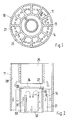
- Radially aligned webs 13 connect the outer wall 11 to the inner wall 12 and divide exhaust ducts 21, which are evenly distributed in large numbers distribute the circumference of section 10 in the desired dimension is cut to length from the extruded aluminum profile. On the webs 13 can protruding ribs 14 to enlarge the surfaces in the exhaust gas channels 21 be molded.
- the upper end face of the cut Section 10 are processed so that only the outer wall 1 are left remains and encloses a combustion chamber 28 which the gas-fed burner 25th receives.
- the subsequent unprocessed part of section 10 is in the area of the liquid channel 20 with a closure plate 26 and a sealing element 27 closed liquid-tight.
- the outgoing from the burner 25 hot exhaust gas enters the exhaust channels 21 and gives heat to the large area Heat exchanger.
- the further heat exchange takes place via the inner wall 12 with the liquid taking place from the bottom, i.e. Exhaust gas outlet side, in the annular liquid inlet channel 31 between the inner wall 12 and the liquid pipe 30 arrives as a liquid return.
- the liquid supplied by the Liquid return increases in the liquid feed channel 31 in countercurrent up to the exhaust gas and gets into the liquid pipe 30, since this with the upper End face is held at a distance from the closure plate 26 and is open.
- the Appropriately heated, liquid reaches the inner receptacle 32 of the liquid tube 30 and flows down to the liquid flow. Doing so the exhaust gas outlet side by reworking section 10 only the Inner wall 12 may be exposed above, so that this itself as a connection for the liquid return can be used.
- the liquid tube 30 itself forms the connection on the exhaust gas outlet side for the liquid flow.
- the section 10 ' essentially of two square base sections 10, which become one integral overall section 10 'are strung together.
- the basic sections 10 each have a liquid channel 20 and a plurality of exhaust gas channels 21 on which each enclose the liquid channel 20. So this square Base sections 10 can be strung together, forms the outer wall 11 a square frame, which in the one-piece design of the entire section 10 'becomes rectangular. Form the adjacent sides of the base side 10 a partition 15.
- the webs 13, which divide the exhaust ducts 21, run in the base sections 10 each radially to the frame walls 11 or to the partition 15, as FIG. 4 clearly shows.
- the burner 25 extends over the entire upper end face of the overall section 10 ', the elongated frame-like outer wall 11 again Can enclose combustion chamber 28.
- a liquid tube 30 is used, which at the top Exhaust gas inlet end again at a distance from the closing plates 26.
- the upper end faces of the liquid tubes 30 are open and end at a distance from associated closure plate 26 so that the liquid transitions from the annular liquid channels 31 into the interior 32 of the liquid tubes 30 is possible.
- the liquid channels are on the lower exhaust gas outlet side of the overall section 10 ' 20, i.e. the inner walls 12 partially exposed and can be used as Connection for the common liquid return 36 can be used while the annular liquid supply channels 31 with the liquid flow 35 are connected.
- the inner walls 12 and the liquid tubes 30 passed through an exhaust manifold 40 covering the entire section 10 'on the exhaust gas outlet side and with one not closer Exhaust system shown and explained in connection.
- the section 10 of the extruded profile also have the exhaust gas channel or channels 21 in the center, wherein liquid channels 20 are formed on the outer walls.
- the exhaust ducts can divide 21 chambers to improve the heat transfer.
- the exhaust gas inlet side is recessed as a combustion chamber 28 around the To be able to record burner 25.
- the direction of flow of the liquid is preferably aligned in counterflow to the direction of the exhaust gas.
Landscapes
- Engineering & Computer Science (AREA)
- Physics & Mathematics (AREA)
- Thermal Sciences (AREA)
- Mechanical Engineering (AREA)
- General Engineering & Computer Science (AREA)
- Chemical & Material Sciences (AREA)
- Combustion & Propulsion (AREA)
- Geometry (AREA)
- Heat-Exchange Devices With Radiators And Conduit Assemblies (AREA)
- Instantaneous Water Boilers, Portable Hot-Water Supply Apparatuses, And Control Of Portable Hot-Water Supply Apparatuses (AREA)
- Details Of Heat-Exchange And Heat-Transfer (AREA)
Applications Claiming Priority (2)
| Application Number | Priority Date | Filing Date | Title |
|---|---|---|---|
| DE10149330 | 2001-10-06 | ||
| DE10149330A DE10149330A1 (de) | 2001-10-06 | 2001-10-06 | Wärmetauscher für ein Gasheizgerät, insbesondere ein Brennwertgerät |
Publications (2)
| Publication Number | Publication Date |
|---|---|
| EP1300636A2 true EP1300636A2 (fr) | 2003-04-09 |
| EP1300636A3 EP1300636A3 (fr) | 2004-04-07 |
Family
ID=7701623
Family Applications (1)
| Application Number | Title | Priority Date | Filing Date |
|---|---|---|---|
| EP02022402A Withdrawn EP1300636A3 (fr) | 2001-10-06 | 2002-10-04 | Echangeur de chaleur pour chaudière à gaz, spécialement chaudière à condensation |
Country Status (2)
| Country | Link |
|---|---|
| EP (1) | EP1300636A3 (fr) |
| DE (1) | DE10149330A1 (fr) |
Families Citing this family (2)
| Publication number | Priority date | Publication date | Assignee | Title |
|---|---|---|---|---|
| CN101676649B (zh) * | 2008-09-16 | 2012-06-27 | 贾祖仪 | 一种热水交换机 |
| DE202008012523U1 (de) | 2008-09-20 | 2010-02-11 | Robert Bosch Gmbh | Wärmetauscher, insbesondere für ein Heizgerät |
Family Cites Families (7)
| Publication number | Priority date | Publication date | Assignee | Title |
|---|---|---|---|---|
| DE1751347A1 (de) * | 1968-05-15 | 1971-10-07 | Steinmueller Gmbh L & C | Stranggepresste Hohlprofile ohne Laengsschweissnaehte an den druckfuehrenden Querschnitten zur Herstellung von dichtgeschweissten Heiz- oder Kuehlflaechen |
| NL8903078A (nl) * | 1989-12-15 | 1991-07-01 | Daalderop Bv | Warmtewisselaar voor een gastoestel, alsmede gastoestel voorzien van een dergelijke warmtewisselaar. |
| GB9012080D0 (en) * | 1990-05-31 | 1990-07-18 | Servotomic Ltd | Improvements in or relating to heat exchangers |
| AT401431B (de) * | 1992-08-11 | 1996-09-25 | Steyr Nutzfahrzeuge | Wärmetauscher |
| NL1001374C2 (nl) * | 1995-10-06 | 1997-04-08 | Holding J H Deckers N V | Warmtewisselaar voor combiketel met centrale verbrandingsruimte. |
| DE69713724T2 (de) * | 1996-12-03 | 2002-11-14 | Calsonic Kansei Corp., Tokio/Tokyo | Befestigungsvorrichtung für Ölkühler und Verfahren zur Befestigung eines Ölkühlers |
| DE19729725A1 (de) * | 1997-07-11 | 1999-01-14 | Hoecker Hans Peter Dipl Ing Fh | Vorrichtung zum Austausch von Wärme |
-
2001
- 2001-10-06 DE DE10149330A patent/DE10149330A1/de not_active Ceased
-
2002
- 2002-10-04 EP EP02022402A patent/EP1300636A3/fr not_active Withdrawn
Also Published As
| Publication number | Publication date |
|---|---|
| EP1300636A3 (fr) | 2004-04-07 |
| DE10149330A1 (de) | 2003-04-17 |
Similar Documents
| Publication | Publication Date | Title |
|---|---|---|
| DE3924411A1 (de) | Rippenrohrwaermetauscher | |
| EP0271434A2 (fr) | Chaudière de chauffage d'acier | |
| EP1136764B1 (fr) | Echangeur de chaleur pour chaudière à gaz à haut rendement | |
| EP2313698B1 (fr) | Chaudière sectionnée en fonte ou en aluminium | |
| DE2742839C2 (fr) | ||
| EP2507562A2 (fr) | Appareil de chauffage | |
| DE102017002038A1 (de) | Kreuzgegenstrom- Wärmeübertrager | |
| EP1278025A2 (fr) | Echangeur de chaleur pour chaudière à gaz, esp. chaudière à condensation | |
| EP1300636A2 (fr) | Echangeur de chaleur pour chaudière à gaz, spécialement chaudière à condensation | |
| EP0177904B1 (fr) | Dispositif pour l'échange de chaleur entre deux gaz en flux croisé | |
| DE3247392C2 (fr) | ||
| DE3428829A1 (de) | Oel/gas-heizkessel | |
| AT396176B (de) | Waermetauscher fuer einen wasserheizer | |
| DE69805841T2 (de) | Flüssigkeitserhitzer | |
| DE4406030C2 (de) | Brennwertkessel | |
| EP1602886B1 (fr) | Chaudière | |
| DE2742745C3 (de) | Wärmetauscher | |
| EP0230982B1 (fr) | Echangeur de chaleur cylindrique, fabriqué avec des éléments de construction préfabriqués, en particulier récupérateur sur cheminée | |
| DE1679301B1 (de) | Rohrregisterheizkoerper mit im Querschnitt H-foermigen Gliedern aus Leichtmetall | |
| WO2011150920A2 (fr) | Echangeur de chaleur | |
| DE3741798A1 (de) | Stahlheizkessel | |
| AT404756B (de) | Wärmetauscher | |
| DE102009032121A1 (de) | Brennwertkessel | |
| AT154624B (de) | Dampferzeuger. | |
| AT5587U1 (de) | Wärmetauscher für einen heizkessel |
Legal Events
| Date | Code | Title | Description |
|---|---|---|---|
| PUAI | Public reference made under article 153(3) epc to a published international application that has entered the european phase |
Free format text: ORIGINAL CODE: 0009012 |
|
| AK | Designated contracting states |
Kind code of ref document: A2 Designated state(s): AT BE BG CH CY CZ DE DK EE ES FI FR GB GR IE IT LI LU MC NL PT SE SK TR Designated state(s): AT BE BG CH CY CZ DE DK EE ES FI FR GB GR IE IT LI LU MC NL PT SE SK TR |
|
| AX | Request for extension of the european patent |
Extension state: AL LT LV MK RO SI |
|
| PUAL | Search report despatched |
Free format text: ORIGINAL CODE: 0009013 |
|
| AK | Designated contracting states |
Kind code of ref document: A3 Designated state(s): AT BE BG CH CY CZ DE DK EE ES FI FR GB GR IE IT LI LU MC NL PT SE SK TR |
|
| AX | Request for extension of the european patent |
Extension state: AL LT LV MK RO SI |
|
| RIC1 | Information provided on ipc code assigned before grant |
Ipc: 7F 28D 7/10 B Ipc: 7F 24H 1/40 A |
|
| AKX | Designation fees paid | ||
| REG | Reference to a national code |
Ref country code: DE Ref legal event code: 8566 |
|
| STAA | Information on the status of an ep patent application or granted ep patent |
Free format text: STATUS: THE APPLICATION IS DEEMED TO BE WITHDRAWN |
|
| 18D | Application deemed to be withdrawn |
Effective date: 20041008 |