EP1300672A1 - Amélioration des performances d'appareils de mesure de transmission optique - Google Patents
Amélioration des performances d'appareils de mesure de transmission optique Download PDFInfo
- Publication number
- EP1300672A1 EP1300672A1 EP02256997A EP02256997A EP1300672A1 EP 1300672 A1 EP1300672 A1 EP 1300672A1 EP 02256997 A EP02256997 A EP 02256997A EP 02256997 A EP02256997 A EP 02256997A EP 1300672 A1 EP1300672 A1 EP 1300672A1
- Authority
- EP
- European Patent Office
- Prior art keywords
- light
- transmissometer
- visibility
- receiver unit
- unit
- Prior art date
- Legal status (The legal status is an assumption and is not a legal conclusion. Google has not performed a legal analysis and makes no representation as to the accuracy of the status listed.)
- Granted
Links
Images


Classifications
-
- G—PHYSICS
- G01—MEASURING; TESTING
- G01N—INVESTIGATING OR ANALYSING MATERIALS BY DETERMINING THEIR CHEMICAL OR PHYSICAL PROPERTIES
- G01N21/00—Investigating or analysing materials by the use of optical means, i.e. using sub-millimetre waves, infrared, visible or ultraviolet light
- G01N21/17—Systems in which incident light is modified in accordance with the properties of the material investigated
- G01N21/47—Scattering, i.e. diffuse reflection
- G01N21/49—Scattering, i.e. diffuse reflection within a body or fluid
- G01N21/53—Scattering, i.e. diffuse reflection within a body or fluid within a flowing fluid, e.g. smoke
- G01N21/538—Scattering, i.e. diffuse reflection within a body or fluid within a flowing fluid, e.g. smoke for determining atmospheric attenuation and visibility
-
- G—PHYSICS
- G01—MEASURING; TESTING
- G01N—INVESTIGATING OR ANALYSING MATERIALS BY DETERMINING THEIR CHEMICAL OR PHYSICAL PROPERTIES
- G01N21/00—Investigating or analysing materials by the use of optical means, i.e. using sub-millimetre waves, infrared, visible or ultraviolet light
- G01N21/01—Arrangements or apparatus for facilitating the optical investigation
- G01N21/15—Preventing contamination of the components of the optical system or obstruction of the light path
Definitions
- This invention relates to transmissometers for measurement of visibility in air, and in particular loss of visibility due to airborne particles.
- a transmissometer measures visual range, giving an indication of the distance at which an object can be visually detected.
- Transmissometers are used in applications such as in airports where the amount of visibility is of critical importance to safety.
- a transmissometer typically includes two units, a light transmitter and a light receiver, which are placed a predetermined distance apart. This distance is referred to as the baseline.
- the light transmitter generates light, typically a pulse of light, which is received at the light receiver.
- the light receiver measures the intensity of the light received from the light transmitter and this intensity measurement is used to calculate the current visual range.
- the light transmitter and light receiver each include a window through which transmitted light passes.
- the windows prevent ingress of contaminants that would degrade performance of the transmissometer. Contamination of the windows that are exposed to the external environment, such as from jet vapour or dust, effects the accuracy of the light sensing. As the contamination increases, the level of the light detected at the light receiver decreases, giving inaccurate results.
- a known method of measuring the amount of window contamination involves calculating a "contamination factor" by measuring the total internal reflection of the window. This is implemented by transmitting a light into the top of the window and measuring the intensity of light received at the bottom. The received light intensity correlates to the contamination factor, and is factored into measured light detected at the light receiver, to correct for losses caused by contamination.
- a known method of reducing window contamination is to provide air flow over the front of the window to reduce the contamination buildup.
- a blower or fan is used produce the airflow.
- Transmissometers used for the determination of visibility require the optical alignment of the light transmitter and the light receiver at each end of the baseline for correct operation, the baseline being the distance between the transmitter and receiver. This adjustment becomes very critical at longer baselines such 75 metres.
- the typical method of alignment comprises manual adjustment of screws or bolts to move the complete optical section of the light transmitter or receiver. This task can be difficult and is time consuming.
- a visibility transmissometer having a light transmitter unit and a light receiver unit, the light transmitter unit being arranged to transmit light via a light pathway to the light receiver unit; the light transmitter unit and the light receiver unit each having a light transmissive window located in the light pathway to isolate the atmosphere within said unit from the outside atmosphere; wherein said light transmissive window includes, in at least one of said light transmitter unit and said light receiver unit, occlusion means operable to occlude at least a part of said light transmissive window to protect it from contanination when it is not transmitting or receiving light.
- said occlusion means includes a cover to cover said light transmissive window when not in use, and uncover said light transmissive window when measurements are being made.
- said occlusion means includes in said light transmissive window, at least two portions, one being an operational portion normally located in said light pathway, and at least one normally obscured portion, said unit having a mechanism to move said light transmissive window between any one of said at least two portions.
- said transmissometer has processor means to determine when any one of said at least two portions becomes contaminated, and actuation means to actuate on the level of contamination exceeding a predetermined level.
- processor means to determine when any one of said at least two portions becomes contaminated, and actuation means to actuate on the level of contamination exceeding a predetermined level.
- the actuation means may provide an alarm indication to indicate that said light transmissive window should be cleaned or replaced, or may control the mechanism to move said light transmissive window to a new said portion.
- said transmissometer includes a communications link between said light transmitter unit and said light receiver unit to enable operation of said mechanisms in said units to be synchronised.
- the processor means will control such synchronisation.
- the light transmissive window may comprise a portion, a length, or a roll of transparent film, with said portions being predetermined designated regions thereof.
- the light transmissive window may comprise a transparent panel with said portions being predetermined designated regions thereof.
- said light transmissive window is formed from a transparent disk, rotatable about a central axis, said portions being spaced radially from said central axis.
- the portions of the transparent disk may be individual glass panels secured within a frame.
- said at least two portions of said light transmissive window include at least one operational portion, one said operational portion normally being located in said light pathway, and a normally obscured reference portion representative of a clean light transmissive window, said mechanism being arranged to move said light transmissive window between said at least one operational portion and said normally obscured reference portion (to move said normally obscured reference portion into and out of said light pathway); said processor means including a comparator to compare transmitted light between said operational portion and said normally obscured reference portion, and said actuation means actuates on the difference between compared transmitted light between said operational portion and said normally obscured reference portion exceeding a predetermined level.
- said light transmissive window includes a plurality of normally obscured operational portions.
- the life of the light transmissive window between cleaning or replacement is five times longer than a single fixed light transmissive window.
- the processor means includes a contamination compensation algorithm to adjust for measured contamination while an operational portion becomes contaminated but remains serviceable.
- said light transmissive window includes at least one peelable transparent layer of film.
- the window needs to be cleaned, it can be accessed and the contaminated outer layer peeled off and removed from the transmissometer. This feature provides fast turnaround time for in-field servicing.
- said transmissometer incorporates, in proximity to said light transmissive window, an electric field generating means located externally thereof.
- said electric field generating means includes a grid of wires located externally of said transmissometer.
- a visibility transmissometer having a light transmitter unit and a light receiver unit, the light transmitter unit being arranged to transmit light via a light pathway to the light receiver unit; the light transmitter unit and preferably also the light receiver unit having an optical device moveable in at least one plane by a mechanism to control the alignment of light transmitted via said light pathway and preferably control the alignment of received light; said transmissometer having processor means to control said mechanism(s), said light transmitter unit and said light receiver unit being connected by a communications link, said processor means being responsive to the level of light received by said light receiver unit and controlling said mechanism(s) to optimise target light to said light receiver unit.
- the optical device may be a laser, a xenon strobe lamp, a detector, and may include lenses and mirrors.
- said mechanism(s) is/are capable of controlling movement of said optical device(s) in two planes.
- one or both said units include in said optical devices, a light reflector located in the light pathway; said light reflector(s) being movable by said mechanism to control the alignment of light transmitted via said light pathway and preferably control the alignment of received light.
- said mechanism(s) is/are capable of controlling movement of said light reflector(s) in two planes.
- said processor means is located in said light transmitter unit, and controls said mechanism in said light transmitter unit in response to a light level signal from said light receiver unit transmitted via said communications link.
- said processor means includes additional processor means located in said light receiver unit, said additional processor means controlling said mechanism in said light receiver unit in response to a light level signal from said light receiver unit.
- said mechanism includes a screw thread drive(s), and alignment is carried out or checked intermittently.
- screw thread drives or worm drives
- said transmissometer includes a light transmissive window through which transmitted light passes, located in at least one of said units, and includes in at least one of said light transmitter unit and said light receiver unit, occlusion means to occlude at least a part of said light transmissive window when not in use.
- said occlusion means includes a cover to cover said light transmissive window when not in use, and uncover said light transmissive window when measurements are being made.
- said transmissometer includes a light transmissive window through which transmitted light passes, located in at least one of said units, said light transmissive window including at least one peelable transparent layer of film.
- said window needs to be cleaned, it can be accessed and the contaminated outer layer peeled off and removed from the transmissometer. This feature provides fast turnaround time for in-field servicing.
- said transmissometer includes a light transmissive window through which transmitted light passes, located in at least one of said units, and incorporates in proximity to said light transmissive window, an electric field generating means located externally thereof.
- said electric field generating means includes a grid of wires located externally of said transmissometer.
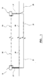
- the embodiment is a visibility transmissometer, for use in measuring visibility in air at airports and the like, and is shown generally in figure 1.
- the visibility transmissometer has a light transmitter unit 11 and a light receiver unit 13.
- the light transmitter unit 11 is arranged to transmit light via a light pathway (indicated as 15) to the light receiver unit 13.
- the standard version of the visibility transmissometer uses in the light transmitter unit 11, a high stability Xenon flash lamp to generate the light required for the measurement by the light receiver unit 13.
- the visibility transmissometer can, in the light transmitter unit 11, use a laser source as an alternative option.
- the laser source of choice is a frequency doubled Nd:YAG laser operating at 532nm, which generates a green light which is close to the peak sensitivity of the human eye.
- the laser output is modulated at 10KHz so that the receiver is able to use highly selective filtering and therefore provide greater accuracy in its measurement.
- the light transmitter unit 11 and light receiver unit 13 are each mounted on a pole 17 above the ground 19, located 75 metres apart from each other, this distance being known as the baseline.
- the light transmitter unit 11 and light receiver unit 13 are connected by a subterranean communications link 21 (which also includes power supply necessary for operation).
- a further subterranean communications link and power feed 23 connects the light receiver unit 13 to monitoring equipment which may be located in the control tower at the airport.
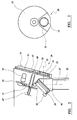
- the units have a housing 25 having a front panel 27. Located in the front panel 27, is a light transmissive aperture 29 which has located therein a light transmissive window 31.
- the units are sealed from the outside atmosphere, to prevent ingress by dust and other contamination which would degrade the performance of the transmissometer. The sealing is assisted by an annular seal 33 located around the periphery of the light transmissive aperture 29, against the light transmissive window 31.
- the units 11, 13 include an optics component 35.
- the optics component 35 In the light transmitter unit 11 the optics component 35 generates a light beam 37, in the light receiver unit 13 the optics component 35 receives the light beam 37.
- the optics component 35 also includes a mirror assembly 39 with a mirror 41 oriented generally to deflect the light beam 37 at an angle of 90°. The fine alignment of the mirror 41 is controlled in two dimensions, by two stepper motors indicated at 43.
- the light transmissive window 31 is circular, and commensurate in size with the front panel 27.
- the light transmissive window 31 has a central mount 45, by which it is secured axially for rotation to a rotatable shaft 47 by a fastener 49.
- the shaft 47 is driven via a mechanism 51 by a motor 53.
- the mechanism 51 includes an arrangement to draw the light transmissive window 31 away from the seal 33 prior to commencement of rotation, to prevent contamination of the seal and consequent smearing of the light transmissive window 31 with deposited contaminants.
- the light transmissive window 31 has six notional positions, comprising a first operational portion, a normally obscured reference portion representative of a clean light transmissive window, and four further operational portions.
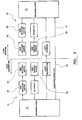
- Processor means in the form of microprocessors 55 are used to make necessary calculations and control the functions which will now be described.
- the amount of contamination is determined by comparing the current level of the light pulse detected at the light receiver unit 13 with the amount of light received when the normally obscured reference portion of the light transmissive window 31, being a reference window of clean glass, is used. This is achieved by temporarily replacing the current operational portion of the light transmissive window 31, both at the light transmitter unit 11 and the light receiver unit 13, with the normally obscured reference portion of the light transmissive window 31. A light flash is then generated from the light transmitter unit 11 and the value of the intensity detected at the light receiver unit 13 is stored and then compared with the value of intensity that was received before the normally obscured reference portions of the light transmissive window 31 were inserted. This difference is used as the contamination factor by the software algorithm calculating true light intensity. The clean normally obscured reference portions of the light transmissive windows 31 at the light transmitter unit 11 and light receiver unit 13 are then replaced with the operational portions of the light transmissive windows 31 that had previously been used before the contamination check.
- This compensation check is automatically carried out on a time interval that is configurable in the light transmitter unit 11 or light receiver unit 13, but which is determined by the local environment eg. dust etc.
- the difference in the light intensity received is used to compensate for the contamination for the period until the next scheduled check.
- the current operational portion is replaced with a clean operational portion of the window 31, by rotating the window 31 to a new position.
- the remainder of the window 31 is sealed from the outer environment, and can be rotated into use at a later date.
- the motor 53 is controlled by the microprocessor 55. Whenever the window 31 is to be rotated, the motor 53 begins to turn, operating the mechanism which draws the window 31 away from the seal 33. After the window 31 is clear of the seal 33, the motor 53 rotates the window 31 until it reaches the required position, where the mechanism automatically pushes the window 31 back on to the seal. The new area of window 31 to be used as an operational portion now meets the seal 33 located on the front panel 27, sealing the interior of the unit 11, 13.
- the window 31 as described gives the transmitter unit 11 or receiver unit 13, five operational portions and the reference portion used for the contamination detection, thus extending the period for maintenance of the window system by five times that of conventional contamination detection systems.
- a maintenance person When the window 31 reaches a stage where all operational portions are severely contaminated, a maintenance person simply replaces the contaminated window 31 with a spare clean window 31. Access to the window 31 can be achieved by removing the front panel 27, and unscrewing the fastener 49. The contaminated window 31 can then be taken to a clean workshop environment and be cleaned, ready for use when required.
- the rotation of the window 31 is controlled by microprocessor 55 in both the transmitter unit 11 and receiver unit 13 and occurs whenever a contamination check is carried out or when a new section of window 31 is to be used.
- Outputs from the microprocessor 55 control a motor drive circuit 57, which operates the motor 53.
- the microprocessor 55 receives feedback from a location sensor 59 confirming when the disk is located in one of the correct positions. Coordination of the rotation between window in the light transmitter unit 11 and the window 31 in the light receiver unit 13 is via the communications link 21.
- Alignment involves the movement of the mirror 41 of the optics components 35 by two motors 43.
- the motors 43 drive fine pitched threaded rods, giving vertical and horizontal adjustment to the alignment.
- a command is given to the light transmitter unit 11 and the light receiver unit 13 via the communications link 23 and 21 for the alignment to occur.
- This command can be also be given from a switch, keypad etc located in the transmitter unit 11 and/or receiver unit 13.
- the alignment is then automatically performed at the transmitter unit 11 and the receiver unit 13, with the mirror being moved in a grid pattern until the optimum light intensity level is obtained at the light receiver unit 13 when a pulse of light is transmitted by the light transmitter unit.
- the optimum light level is where the received light is received centrally by the light receiver unit, and not at the edge of the beam. While this may or may not equate to maximum light, depending upon optics, this prevents erroneous errors that could occur where the edge of the beam is aligned to the receiver unit, and there is vibration which could cause the beam to move off-target.
- the location of optimum light intensisty is then stored in the microprocessor memory and used as the aligned location for the transmitter unit 11 and receiver unit 13.
- the alignment can be checked or redone at any time by giving an alignment command.
- the automated optical alignment of the transmitter or receiver is carried out by moving the mirror 41 in two axes that give horizontal and vertical adjustment.
- the alignment is carried out using the two stepper motors 43 controlled by the microprocessors 55, via motor drive interfaces 61.
- Both horizontal and vertical adjustments have location sensors 63 to provide adjustment position to the microprocessors 55, enabling them to determine a zero position from which the current mirror location is determined by counting pulses used to actuate the stepper motors 43.
- Coordination of the rotation between the transmitter and the receiver is via the communications link 21 between the microprocessor 55 in the transmitter unit 11 microprocessor 55 in the receiver unit 13.
- the motor 53 drives a wheel 67 which has an eccentric pin 69 located on a raised platform 71.
- the raised platform 71 has two sloping approach surfaces 73.
- the wheel 67 co-operates with a hexagonal plate 75 having spaced guide slots 77 which receive the pin 69.
- the plate 75 is fixed to the shaft 47, and rotates with the window 31.
- the shaft 47 is mounted on a pin 79, and is biased by a spring-loading mechanism (not shown) between the pin 79 and the shaft 47, to urge the window 31 toward the annular seal 33, for sealing during normal operation.
- the transmissometer of the embodiment and invention provides extended operational life, and simple set up and alignment, compared with previous known types. With the alignment as described, the transmitter unit 11 and receiver unit 13 can be aimed approximately when being installed, and fine alignment automatically performed by the on board microprocessors 55. While the mirrors 41 are moved in the embodiment, the entire optical unit could be moved, in an alternative embodiment.
Landscapes
- General Health & Medical Sciences (AREA)
- Physics & Mathematics (AREA)
- Life Sciences & Earth Sciences (AREA)
- Chemical & Material Sciences (AREA)
- Analytical Chemistry (AREA)
- Biochemistry (AREA)
- Immunology (AREA)
- General Physics & Mathematics (AREA)
- Health & Medical Sciences (AREA)
- Pathology (AREA)
- Investigating Or Analysing Materials By Optical Means (AREA)
- Optical Fibers, Optical Fiber Cores, And Optical Fiber Bundles (AREA)
- Arrangements For Transmission Of Measured Signals (AREA)
- Acyclic And Carbocyclic Compounds In Medicinal Compositions (AREA)
Applications Claiming Priority (2)
| Application Number | Priority Date | Filing Date | Title |
|---|---|---|---|
| AUPR8131A AUPR813101A0 (en) | 2001-10-08 | 2001-10-08 | Improvements in transmissometers |
| AUPQ813101 | 2001-10-08 |
Related Child Applications (1)
| Application Number | Title | Priority Date | Filing Date |
|---|---|---|---|
| EP09166589.3 Division-Into | 2009-07-28 |
Publications (2)
| Publication Number | Publication Date |
|---|---|
| EP1300672A1 true EP1300672A1 (fr) | 2003-04-09 |
| EP1300672B1 EP1300672B1 (fr) | 2010-04-28 |
Family
ID=3831959
Family Applications (2)
| Application Number | Title | Priority Date | Filing Date |
|---|---|---|---|
| EP02256959A Expired - Lifetime EP1300671B1 (fr) | 2001-10-08 | 2002-10-08 | Amélioration des performances d'appareils de mesure de transmission optique |
| EP02256997A Expired - Lifetime EP1300672B1 (fr) | 2001-10-08 | 2002-10-08 | Amélioration des performances d'appareils de mesure de transmission optique |
Family Applications Before (1)
| Application Number | Title | Priority Date | Filing Date |
|---|---|---|---|
| EP02256959A Expired - Lifetime EP1300671B1 (fr) | 2001-10-08 | 2002-10-08 | Amélioration des performances d'appareils de mesure de transmission optique |
Country Status (5)
| Country | Link |
|---|---|
| EP (2) | EP1300671B1 (fr) |
| AT (2) | ATE285573T1 (fr) |
| AU (3) | AUPR813101A0 (fr) |
| DE (2) | DE60202337T2 (fr) |
| ES (1) | ES2236450T3 (fr) |
Cited By (3)
| Publication number | Priority date | Publication date | Assignee | Title |
|---|---|---|---|---|
| WO2007104925A3 (fr) * | 2006-03-11 | 2007-12-06 | Univ Durham | Transmissometre optique, ainsi qu'une source de lumiere et un photodetecteur destines a ce transmissometre |
| GB2450132A (en) * | 2007-06-13 | 2008-12-17 | Hochiki Co | Optical beam reflective-type smoke detector with a system for specifying the reflector position |
| CN113804655A (zh) * | 2021-09-10 | 2021-12-17 | 天津酷云网络科技有限公司 | 一种港口能见度监测系统及监测方法 |
Families Citing this family (6)
| Publication number | Priority date | Publication date | Assignee | Title |
|---|---|---|---|---|
| DE102004006961B3 (de) * | 2004-02-09 | 2005-08-11 | Vaisala Gmbh | Vorrichtung und Verfahren zur Messung der atmosphärischen Transmission und Bestimmung der meteorologischen Sichtweite |
| DE102010018409A1 (de) | 2010-04-13 | 2012-06-14 | Arkadij Gershman | Verfahren zur Sichtweitenmessung und die Einrichtung um es realisieren |
| DE102010026800A1 (de) | 2010-07-10 | 2012-01-12 | Arkadij Gershman | Das Verfahren und die Einrichtung für die Instrumentalbestimmung der Sichtweite |
| DE202010016707U1 (de) | 2010-12-17 | 2011-03-24 | Gershman, Arkadij | Das Gerät für die Instrumentalbestimmung der Sichtweite |
| DE202010016708U1 (de) | 2010-12-17 | 2011-05-26 | Gershman, Arkadij, 30559 | Sichtweitenmeßgerät mit dem Lichtstrahler und Diversitylichtempfang |
| CN102253013A (zh) * | 2011-04-29 | 2011-11-23 | 陈伟 | 一种应用于交通领域的透射法能见度检测装置及其检测方法 |
Citations (4)
| Publication number | Priority date | Publication date | Assignee | Title |
|---|---|---|---|---|
| US4520360A (en) * | 1982-09-20 | 1985-05-28 | General Signal Corporation | Sensing vertical and horizontal visibility |
| US4605302A (en) * | 1983-04-18 | 1986-08-12 | Asea Aktiebolag | Cloud height measuring device with compensation for window fouling |
| US5504577A (en) * | 1992-07-30 | 1996-04-02 | Vaisala Oy | Method and apparatus for measuring meteorological visibility and scattering of light, said apparatus utilizing common optics for transmission and reception |
| US5787385A (en) * | 1996-02-28 | 1998-07-28 | Sun Microsystems, Inc. | Computer controlled laser fog tracking |
Family Cites Families (5)
| Publication number | Priority date | Publication date | Assignee | Title |
|---|---|---|---|---|
| DE3022114C2 (de) * | 1980-06-12 | 1983-05-26 | Erwin Sick Gmbh Optik-Elektronik, 7808 Waldkirch | Vorrichtung zur Messung des optischen Transmissions- bzw. Absorptionsvermögens eines lichtdurchlässigen Materials |
| US4381153A (en) * | 1980-08-28 | 1983-04-26 | The Babcock & Wilcox Company | Opacity monitor |
| US5373367A (en) * | 1992-10-21 | 1994-12-13 | Qualimetrics, Inc. | Multiple angle and redundant visibility sensor |
| DE59510550D1 (de) * | 1995-05-31 | 2003-03-13 | Vaisala Impulsphysik Gmbh | Sichtweitenmessgerät |
| AU3376199A (en) * | 1998-04-01 | 1999-10-18 | Sentec Corporation | Visibility sensor system |
-
2001
- 2001-10-08 AU AUPR8131A patent/AUPR813101A0/en not_active Abandoned
-
2002
- 2002-10-08 AU AU2002301358A patent/AU2002301358B2/en not_active Ceased
- 2002-10-08 EP EP02256959A patent/EP1300671B1/fr not_active Expired - Lifetime
- 2002-10-08 AU AU2002301354A patent/AU2002301354B2/en not_active Ceased
- 2002-10-08 DE DE60202337T patent/DE60202337T2/de not_active Expired - Lifetime
- 2002-10-08 DE DE60236131T patent/DE60236131D1/de not_active Expired - Lifetime
- 2002-10-08 ES ES02256959T patent/ES2236450T3/es not_active Expired - Lifetime
- 2002-10-08 EP EP02256997A patent/EP1300672B1/fr not_active Expired - Lifetime
- 2002-10-08 AT AT02256959T patent/ATE285573T1/de not_active IP Right Cessation
- 2002-10-08 AT AT02256997T patent/ATE466273T1/de not_active IP Right Cessation
Patent Citations (4)
| Publication number | Priority date | Publication date | Assignee | Title |
|---|---|---|---|---|
| US4520360A (en) * | 1982-09-20 | 1985-05-28 | General Signal Corporation | Sensing vertical and horizontal visibility |
| US4605302A (en) * | 1983-04-18 | 1986-08-12 | Asea Aktiebolag | Cloud height measuring device with compensation for window fouling |
| US5504577A (en) * | 1992-07-30 | 1996-04-02 | Vaisala Oy | Method and apparatus for measuring meteorological visibility and scattering of light, said apparatus utilizing common optics for transmission and reception |
| US5787385A (en) * | 1996-02-28 | 1998-07-28 | Sun Microsystems, Inc. | Computer controlled laser fog tracking |
Cited By (5)
| Publication number | Priority date | Publication date | Assignee | Title |
|---|---|---|---|---|
| WO2007104925A3 (fr) * | 2006-03-11 | 2007-12-06 | Univ Durham | Transmissometre optique, ainsi qu'une source de lumiere et un photodetecteur destines a ce transmissometre |
| GB2450132A (en) * | 2007-06-13 | 2008-12-17 | Hochiki Co | Optical beam reflective-type smoke detector with a system for specifying the reflector position |
| GB2450132B (en) * | 2007-06-13 | 2012-06-20 | Hochiki Co | Position specifiying system |
| CN113804655A (zh) * | 2021-09-10 | 2021-12-17 | 天津酷云网络科技有限公司 | 一种港口能见度监测系统及监测方法 |
| CN113804655B (zh) * | 2021-09-10 | 2025-08-29 | 天津酷云网络科技有限公司 | 一种港口能见度监测系统及监测方法 |
Also Published As
| Publication number | Publication date |
|---|---|
| EP1300671B1 (fr) | 2004-12-22 |
| EP1300672B1 (fr) | 2010-04-28 |
| EP1300671A1 (fr) | 2003-04-09 |
| DE60236131D1 (de) | 2010-06-10 |
| ES2236450T3 (es) | 2005-07-16 |
| DE60202337D1 (de) | 2005-01-27 |
| ATE285573T1 (de) | 2005-01-15 |
| DE60202337T2 (de) | 2005-12-08 |
| ATE466273T1 (de) | 2010-05-15 |
| AU2002301354B2 (en) | 2006-12-21 |
| AU2002301358B2 (en) | 2006-09-28 |
| AUPR813101A0 (en) | 2001-11-01 |
Similar Documents
| Publication | Publication Date | Title |
|---|---|---|
| EP1300671B1 (fr) | Amélioration des performances d'appareils de mesure de transmission optique | |
| EP0081245A2 (fr) | Pyromètre avec installation pour le contrôle de le propreté de la fenêtre de visée | |
| JP4481825B2 (ja) | 赤外線測定装置、及び、製造工程への赤外線測定装置のオンライン適用方法 | |
| US7477376B2 (en) | Self-calibrating optical reflectance probe system | |
| JPH0776999B2 (ja) | レ−ザ−使用設備の安全装置 | |
| JPH02129581A (ja) | 平面内を移動する物体、特に航空機の位置を検知する装置 | |
| KR20190021391A (ko) | 엣지 노광 장치 및 방법 | |
| AU2009201367A1 (en) | Apparatus and method for measuring atmospheric transmission and determining meteorological visual range | |
| JPS63173904A (ja) | 非接触空間測定およびその装置 | |
| US5805658A (en) | Methods and apparatus for detecting gantry interference in a computed tomography system | |
| US5004922A (en) | Optical fiber scanning system for heat sensing | |
| CN113557106B (zh) | 测量设备和方法 | |
| EP2156420A1 (fr) | Système de spécification de position | |
| Cannon | A camera for photography of atomospheric particles from aircraft | |
| EP3901616B1 (fr) | Procédés, appareils et systèmes de diagnostic de désalignement dans des dispositifs de détection de gaz | |
| JPH0372241A (ja) | 光電式煙感知器の感度調整方法及び感度調整装置 | |
| US20250237593A1 (en) | Opto-mechanical Analysis Device For Determining Particulate Matter In A Measurement Gas | |
| JPH07226353A (ja) | 露光装置 | |
| KR20160139586A (ko) | 회전 광학계를 이용한 레이저 터치센서 | |
| AU2011218728A1 (en) | Apparatus and method for measuring atmospheric transmission and determining meteorological visual range | |
| JPH0518815A (ja) | レーザビーム位置補正装置 | |
| JP2000025697A (ja) | Papi監視装置 | |
| Viezee et al. | Visibility Measurement Techniques | |
| KR20020076594A (ko) | 반도체소자 제조용 스테퍼설비의 포커싱 변동 방지시스템 |
Legal Events
| Date | Code | Title | Description |
|---|---|---|---|
| PUAI | Public reference made under article 153(3) epc to a published international application that has entered the european phase |
Free format text: ORIGINAL CODE: 0009012 |
|
| AK | Designated contracting states |
Kind code of ref document: A1 Designated state(s): AT BE BG CH CY CZ DE DK EE ES FI FR GB GR IE IT LI LU MC NL PT SE SK TR Designated state(s): AT BE BG CH CY CZ DE DK EE ES FI FR GB GR IE IT LI LU MC NL PT SE SK TR |
|
| AX | Request for extension of the european patent |
Extension state: AL LT LV MK RO SI |
|
| 17P | Request for examination filed |
Effective date: 20031009 |
|
| AKX | Designation fees paid |
Designated state(s): AT BE BG CH CY CZ DE DK EE ES FI FR GB GR IE IT LI LU MC NL PT SE SK TR |
|
| 17Q | First examination report despatched |
Effective date: 20041124 |
|
| APBN | Date of receipt of notice of appeal recorded |
Free format text: ORIGINAL CODE: EPIDOSNNOA2E |
|
| APBR | Date of receipt of statement of grounds of appeal recorded |
Free format text: ORIGINAL CODE: EPIDOSNNOA3E |
|
| APAF | Appeal reference modified |
Free format text: ORIGINAL CODE: EPIDOSCREFNE |
|
| RAP1 | Party data changed (applicant data changed or rights of an application transferred) |
Owner name: TELVENT AUSTRALIA PTY LTD |
|
| APBT | Appeal procedure closed |
Free format text: ORIGINAL CODE: EPIDOSNNOA9E |
|
| GRAP | Despatch of communication of intention to grant a patent |
Free format text: ORIGINAL CODE: EPIDOSNIGR1 |
|
| GRAS | Grant fee paid |
Free format text: ORIGINAL CODE: EPIDOSNIGR3 |
|
| GRAA | (expected) grant |
Free format text: ORIGINAL CODE: 0009210 |
|
| AK | Designated contracting states |
Kind code of ref document: B1 Designated state(s): AT BE BG CH CY CZ DE DK EE ES FI FR GB GR IE IT LI LU MC NL PT SE SK TR |
|
| REG | Reference to a national code |
Ref country code: GB Ref legal event code: FG4D |
|
| REG | Reference to a national code |
Ref country code: CH Ref legal event code: EP |
|
| REG | Reference to a national code |
Ref country code: IE Ref legal event code: FG4D |
|
| REF | Corresponds to: |
Ref document number: 60236131 Country of ref document: DE Date of ref document: 20100610 Kind code of ref document: P |
|
| REG | Reference to a national code |
Ref country code: NL Ref legal event code: T3 |
|
| PG25 | Lapsed in a contracting state [announced via postgrant information from national office to epo] |
Ref country code: SE Free format text: LAPSE BECAUSE OF FAILURE TO SUBMIT A TRANSLATION OF THE DESCRIPTION OR TO PAY THE FEE WITHIN THE PRESCRIBED TIME-LIMIT Effective date: 20100428 Ref country code: ES Free format text: LAPSE BECAUSE OF FAILURE TO SUBMIT A TRANSLATION OF THE DESCRIPTION OR TO PAY THE FEE WITHIN THE PRESCRIBED TIME-LIMIT Effective date: 20100808 |
|
| PG25 | Lapsed in a contracting state [announced via postgrant information from national office to epo] |
Ref country code: FI Free format text: LAPSE BECAUSE OF FAILURE TO SUBMIT A TRANSLATION OF THE DESCRIPTION OR TO PAY THE FEE WITHIN THE PRESCRIBED TIME-LIMIT Effective date: 20100428 Ref country code: AT Free format text: LAPSE BECAUSE OF FAILURE TO SUBMIT A TRANSLATION OF THE DESCRIPTION OR TO PAY THE FEE WITHIN THE PRESCRIBED TIME-LIMIT Effective date: 20100428 |
|
| PG25 | Lapsed in a contracting state [announced via postgrant information from national office to epo] |
Ref country code: GR Free format text: LAPSE BECAUSE OF FAILURE TO SUBMIT A TRANSLATION OF THE DESCRIPTION OR TO PAY THE FEE WITHIN THE PRESCRIBED TIME-LIMIT Effective date: 20100729 Ref country code: CY Free format text: LAPSE BECAUSE OF FAILURE TO SUBMIT A TRANSLATION OF THE DESCRIPTION OR TO PAY THE FEE WITHIN THE PRESCRIBED TIME-LIMIT Effective date: 20100428 |
|
| PG25 | Lapsed in a contracting state [announced via postgrant information from national office to epo] |
Ref country code: PT Free format text: LAPSE BECAUSE OF FAILURE TO SUBMIT A TRANSLATION OF THE DESCRIPTION OR TO PAY THE FEE WITHIN THE PRESCRIBED TIME-LIMIT Effective date: 20100830 Ref country code: EE Free format text: LAPSE BECAUSE OF FAILURE TO SUBMIT A TRANSLATION OF THE DESCRIPTION OR TO PAY THE FEE WITHIN THE PRESCRIBED TIME-LIMIT Effective date: 20100428 Ref country code: DK Free format text: LAPSE BECAUSE OF FAILURE TO SUBMIT A TRANSLATION OF THE DESCRIPTION OR TO PAY THE FEE WITHIN THE PRESCRIBED TIME-LIMIT Effective date: 20100428 |
|
| PG25 | Lapsed in a contracting state [announced via postgrant information from national office to epo] |
Ref country code: SK Free format text: LAPSE BECAUSE OF FAILURE TO SUBMIT A TRANSLATION OF THE DESCRIPTION OR TO PAY THE FEE WITHIN THE PRESCRIBED TIME-LIMIT Effective date: 20100428 Ref country code: CZ Free format text: LAPSE BECAUSE OF FAILURE TO SUBMIT A TRANSLATION OF THE DESCRIPTION OR TO PAY THE FEE WITHIN THE PRESCRIBED TIME-LIMIT Effective date: 20100428 |
|
| PLBE | No opposition filed within time limit |
Free format text: ORIGINAL CODE: 0009261 |
|
| STAA | Information on the status of an ep patent application or granted ep patent |
Free format text: STATUS: NO OPPOSITION FILED WITHIN TIME LIMIT |
|
| PG25 | Lapsed in a contracting state [announced via postgrant information from national office to epo] |
Ref country code: IT Free format text: LAPSE BECAUSE OF FAILURE TO SUBMIT A TRANSLATION OF THE DESCRIPTION OR TO PAY THE FEE WITHIN THE PRESCRIBED TIME-LIMIT Effective date: 20100428 |
|
| 26N | No opposition filed |
Effective date: 20110131 |
|
| PG25 | Lapsed in a contracting state [announced via postgrant information from national office to epo] |
Ref country code: MC Free format text: LAPSE BECAUSE OF NON-PAYMENT OF DUE FEES Effective date: 20101031 |
|
| REG | Reference to a national code |
Ref country code: CH Ref legal event code: PL |
|
| PG25 | Lapsed in a contracting state [announced via postgrant information from national office to epo] |
Ref country code: FR Free format text: LAPSE BECAUSE OF NON-PAYMENT OF DUE FEES Effective date: 20101102 Ref country code: LI Free format text: LAPSE BECAUSE OF NON-PAYMENT OF DUE FEES Effective date: 20101031 Ref country code: CH Free format text: LAPSE BECAUSE OF NON-PAYMENT OF DUE FEES Effective date: 20101031 |
|
| REG | Reference to a national code |
Ref country code: FR Ref legal event code: ST Effective date: 20110630 |
|
| PG25 | Lapsed in a contracting state [announced via postgrant information from national office to epo] |
Ref country code: BG Free format text: LAPSE BECAUSE OF FAILURE TO SUBMIT A TRANSLATION OF THE DESCRIPTION OR TO PAY THE FEE WITHIN THE PRESCRIBED TIME-LIMIT Effective date: 20100428 |
|
| PG25 | Lapsed in a contracting state [announced via postgrant information from national office to epo] |
Ref country code: TR Free format text: LAPSE BECAUSE OF FAILURE TO SUBMIT A TRANSLATION OF THE DESCRIPTION OR TO PAY THE FEE WITHIN THE PRESCRIBED TIME-LIMIT Effective date: 20100428 |
|
| PG25 | Lapsed in a contracting state [announced via postgrant information from national office to epo] |
Ref country code: BG Free format text: LAPSE BECAUSE OF FAILURE TO SUBMIT A TRANSLATION OF THE DESCRIPTION OR TO PAY THE FEE WITHIN THE PRESCRIBED TIME-LIMIT Effective date: 20100728 |
|
| REG | Reference to a national code |
Ref country code: IE Ref legal event code: MM4A |
|
| PG25 | Lapsed in a contracting state [announced via postgrant information from national office to epo] |
Ref country code: IE Free format text: LAPSE BECAUSE OF NON-PAYMENT OF DUE FEES Effective date: 20171008 |
|
| PGFP | Annual fee paid to national office [announced via postgrant information from national office to epo] |
Ref country code: LU Payment date: 20191028 Year of fee payment: 18 |
|
| PGFP | Annual fee paid to national office [announced via postgrant information from national office to epo] |
Ref country code: NL Payment date: 20191026 Year of fee payment: 18 Ref country code: DE Payment date: 20191029 Year of fee payment: 18 |
|
| PGFP | Annual fee paid to national office [announced via postgrant information from national office to epo] |
Ref country code: BE Payment date: 20191028 Year of fee payment: 18 |
|
| REG | Reference to a national code |
Ref country code: DE Ref legal event code: R119 Ref document number: 60236131 Country of ref document: DE |
|
| REG | Reference to a national code |
Ref country code: NL Ref legal event code: MM Effective date: 20201101 |
|
| PG25 | Lapsed in a contracting state [announced via postgrant information from national office to epo] |
Ref country code: LU Free format text: LAPSE BECAUSE OF NON-PAYMENT OF DUE FEES Effective date: 20201008 |
|
| REG | Reference to a national code |
Ref country code: BE Ref legal event code: MM Effective date: 20201031 |
|
| PG25 | Lapsed in a contracting state [announced via postgrant information from national office to epo] |
Ref country code: NL Free format text: LAPSE BECAUSE OF NON-PAYMENT OF DUE FEES Effective date: 20201101 Ref country code: DE Free format text: LAPSE BECAUSE OF NON-PAYMENT OF DUE FEES Effective date: 20210501 |
|
| PG25 | Lapsed in a contracting state [announced via postgrant information from national office to epo] |
Ref country code: BE Free format text: LAPSE BECAUSE OF NON-PAYMENT OF DUE FEES Effective date: 20201031 |
|
| PGFP | Annual fee paid to national office [announced via postgrant information from national office to epo] |
Ref country code: GB Payment date: 20211027 Year of fee payment: 20 |
|
| REG | Reference to a national code |
Ref country code: GB Ref legal event code: PE20 Expiry date: 20221007 |
|
| PG25 | Lapsed in a contracting state [announced via postgrant information from national office to epo] |
Ref country code: GB Free format text: LAPSE BECAUSE OF EXPIRATION OF PROTECTION Effective date: 20221007 |