EP1300687B1 - Dispositif pour la mesure des champs magnétiques - Google Patents
Dispositif pour la mesure des champs magnétiques Download PDFInfo
- Publication number
- EP1300687B1 EP1300687B1 EP02079951A EP02079951A EP1300687B1 EP 1300687 B1 EP1300687 B1 EP 1300687B1 EP 02079951 A EP02079951 A EP 02079951A EP 02079951 A EP02079951 A EP 02079951A EP 1300687 B1 EP1300687 B1 EP 1300687B1
- Authority
- EP
- European Patent Office
- Prior art keywords
- magnetic field
- magnetization
- sensor elements
- field sensors
- central axis
- Prior art date
- Legal status (The legal status is an assumption and is not a legal conclusion. Google has not performed a legal analysis and makes no representation as to the accuracy of the status listed.)
- Expired - Lifetime
Links
Images
Classifications
-
- G—PHYSICS
- G01—MEASURING; TESTING
- G01R—MEASURING ELECTRIC VARIABLES; MEASURING MAGNETIC VARIABLES
- G01R33/00—Arrangements or instruments for measuring magnetic variables
- G01R33/02—Measuring direction or magnitude of magnetic fields or magnetic flux
- G01R33/06—Measuring direction or magnitude of magnetic fields or magnetic flux using galvano-magnetic devices
- G01R33/09—Magnetoresistive devices
-
- G—PHYSICS
- G01—MEASURING; TESTING
- G01R—MEASURING ELECTRIC VARIABLES; MEASURING MAGNETIC VARIABLES
- G01R33/00—Arrangements or instruments for measuring magnetic variables
- G01R33/02—Measuring direction or magnitude of magnetic fields or magnetic flux
- G01R33/0206—Three-component magnetometers
Definitions
- the invention relates to a device for measuring magnetic fields, comprising an assembly consisting of two magnetic field sensors, each of which comprises a number of magnetoresistive sensor elements which are situated in one plane and which have the same privileged directions of magnetization, said sensor elements being connected on the one side to a power supply circuit and on the other side to a signal processing circuit, the privileged directions of magnetization of the sensor elements of different magnetic field sensors being different, said assembly of magnetic field sensors being arranged within a magnetization coil which is formed as an electric conductor which extends around a central axis in a number of turns and which is arranged to generate an auxiliary magnetic field extending parallel to the central axis, the magnetic field sensors being arranged within the magnetization coil in such a manner that the angle enclosed by the central axis relative to the normal to the plane of the sensor elements is the same for each of the magnetic field sensors and that the auxiliary magnetic field at the area of each of the magnetic field sensors contains a component which extends parallel to the privileged direction of magnetization of the sensor elements of the relevant magnetic field
- a device of this kind is known from Philips Technical Publication 268.
- the magnetization coil is connected to a current pulse generator which is arranged to supply the magnetization coil with current pulses of opposite current direction in an alternating fashion, the arrangement being such that each current pulse generates a magnetic field in the magnetization coil which extends parallel to the privileged directions of magnetization of the sensor elements and which is strong enough to reverse the direction of the internal magnetization of the sensor elements.
- the reversal of the internal magnetization of the sensor elements serves to eliminate effects disturbing the measurement, for example as caused by manufacturing tolerances and by drift due to temperature variations.
- the assembly of the known device may comprise two magnetic field sensors which are mounted perpendicularly to one another, as shown in Fig.
- the known device is suitable. However, it may then be objectionable that the magnetization coil is comparatively voluminous and heavy because it must enclose the entire volume defined by the mutually perpendicular magnetic field sensors. Consequently, the known device is not very well suitable for applications where at least the part containing the magnetic field sensor must be very small and light.
- An example of such an application is a compass in a vehicle, for example a car.
- the device then serves to detect the direction of the horizontal components of the terrestrial magnetic field and it would be desirable to mount the magnetic field sensor outside the car body, because the car body generally comprises a large amount of iron and thus has a disturbing effect on the local terrestrial field.
- a suitable location for the sensor is, for example the tip of an aerial mounted on the vehicle.
- the sensor and the magnetization coil connected thereto should then be extremely small and light.
- the associated circuits can then be accommodated within the vehicle, so that they may be more voluminous and heavier.
- the device in accordance with the invention comprises an assembly of two magnetic field sensors, each of which comprises a number of magnetoresistive sensor elements which are situated in one plane and which have the same privileged directions of magnetization, said sensor elements being connected on the one side to a power supply circuit and on the other side to a signal processing circuit, the privileged directions of magnetization of the sensor elements of different magnetic field sensors being different, said assembly of magnetic field sensors being arranged within a magnetization coil which is formed as an electric conductor which extends around a central axis in a number of turns and which is arranged to generate an auxiliary magnetic field extending parallel to the central axis, the magnetic field sensors being arranged within the magnetization coil in such a manner that the angle enclosed by the central axis relative to the normal to the plane of the sensor elements is the same for each of the magnetic field sensors and that the auxiliary magnetic field at the area of each of the magnetic field sensors contains a component which extends parallel to the privileged direction of magnetization of the sensor elements of the relevant magnetic field sensor, wherein the two magnetic field
- the auxiliary magnetic field has a component parallel to the privileged direction of magnetization of each of the sensor elements, these components being equally large for all sensor elements.
- the device is suitable for the measurement of two mutually perpendicular components of a magnetic field. Because the sensor elements of the two magnetic field sensors are situated in one plane or in mutually parallel planes, the assembly consisting of the two magnetic field sensors almost completely fills a very small, block-shaped volume.
- the magnetization coil may have a shape adapted to the shape of this volume, so that it can be substantially smaller than the magnetization coil of the known device.
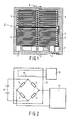
- Fig. 1 shows a magnetic field sensor 1 which is known per se and which is based on the magnetoresistive effect.
- This is the phenomenon that the electric resistance of a current-carrying magnetic material changes in the presence of an external magnetic field. This change is caused by a rotation of the magnetization relative to the current direction.
- permalloy a ferromagnetic alloy containing 20% iron and 80% nickel
- a rotation of the magnetization through 90 0 (caused by an external magnetic field extending perpendicularly to the current direction) will cause a change in resistance of from 2 to 3%.
- the magnetic field sensor shown (Philips type KMZ 10) four magnetoresistive sensor elements 3 are provided on a silicon substrate 2.
- Each of the sensor elements 3 is formed by a meander-like strip of permalloy having a privileged direction of magnetization parallel to the longitudinal direction of the strip, i.e. in the direction of the arrow 5.
- the ends of the sensor elements 3 are interconnected so that they form the four branches of a Wheatstone bridge.
- the degree of unbalance of the bridge can be used as a measure of the variation of the magnetic field strength in the plane of the sensor elements 3 and perpendicular to the direction of an electric current flowing through the sensor elements.
- the bridge circuit formed by the sensor elements 3 can be connected, via connection points 7, on the one side to a power supply circuit on the other side and to a signal processing circuit.
- Fig. 2 shows a block diagram of an embodiment of a device for measuring magnetic fields in which a magnetic field sensor of the type shown in Fig. 1 is used.
- the bridge circuit formed by the sensor elements 3 is connected on the one side to a power supply circuit 9 (a battery in the present case) and to a signal processing circuit 11 on the other side. Examples of suitable signal processing circuits are described, for example in the cited Philips Technical Publication 268.
- the cited publication also mentions that for the elimination of offset effects it is desirable to mount the magnetic field sensor in such a manner that the sensor elements 3 are subject to an auxiliary magnetic field generated by a magnetization coil 13.
- the magnetization coil 13 is connected to a current pulse generator 15 which is arranged to supply the magnetization coil 13 with current pulses of opposite current direction in an alternating fashion, so that oppositely directed auxiliary magnetic fields are alternately generated in the magnetization coil.
- the magnetization coil 13 is arranged in such a manner that the auxiliary magnetic fields generated in this coil extend parallel to the privileged direction of magnetization 5 of the sensor elements 3.
- the properties of the magnetization coil 13 and the current intensity supplied by the current pulse generator 15 are chosen so that the generated auxiliary magnetic fields are strong enough to reverse the direction of the internal magnetization of the sensor elements.
- Fig. 2 shows only one magnetic field sensor.
- two or more magnetic field sensors are combined so as to form an assembly which constitutes a sensor part 17 in conjunction with a single magnetization coil 13.
- the auxiliary magnetic fields generated by the magnetization coil 13 contain components which extend parallel to the privileged directions of magnetization 5 of the sensor elements 3 of each magnetic field sensor. These components are all of the same magnitude.
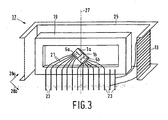
- Fig. 3 shows an embodiment of a sensor part 17 for a device capable of determining the magnitude and direction of two mutually perpendicular components of a magnetic field.
- a device of this kind can be used, for example in a magnetic compass which is sensitive to the horizontal components of the terrestrial magnetic field.
- the sensor part 17 comprises an assembly of two magnetic field sensors 1a and 1b which are mounted together in a housing 19 of a non-magnetic material, for example a suitable synthetic material.
- the two magnetic field sensors 1a and 1b are mounted so that their sensor elements (not separately shown in Fig. 3 ) are situated in one plane and the privileged directions of magnetization 5a and 5b extend perpendicularly to one another.
- the sensor elements are connected to connection pins 23 of the housing 19 via connection wires 21.
- the housing 19 is enclosed by a coil former 25 of a synthetic material on which the magnetization coil 13 is wound.
- the magnetization coil 13 consists of an electrically conductive wire which extends around a central axis 27 in a number of turns, which central axis encloses an angle of 45 0 relative to each of the privileged directions 5a and 5b.
- the two ends of the wire constituting the magnetization coil 13 are connected to two of the connection pins 23.
- an auxiliary magnetic field H is generated in this coil which extends parallel to the central axis 27 so that it encloses an angle of 45 0 relative to each of the privileged directions.
- the magnitude of a component H( ⁇ ) in a direction enclosing an angle ⁇ relative to a magnetic field H equals Hcos ⁇ .
- the thickness of the assembly (being the dimension in a direction perpendicular to said plane) is very small. Therefore, the thickness of the housing 19 may also be very small.
- the width of the housing 19 (being the dimension in a direction perpendicular to said direction and perpendicular to the central axis 27, i.e. from left to right in the Figure) is determined by the space required for the connection pins 23.
- the dimensions of the coil former 25 are chosen so that the housing 19 fits in the cavity of the coil former with a slight clearance. The space within the coil former 25 is thus very efficiently used and the complete sensor part 17 can be very small and light.
- the two magnetic field sensors 1a and 1b are not adjacently arranged but stacked with the privileged directions 5a and 5b oriented in the same way as in the Figure.
- the planes of the sensor elements extend parallel to one another and the assembly will have a thickness which is larger and a width which is smaller than in the case shown.
- the cross-section of the housing 19 should then be more square and the connection pins 23 can then be arranged, for example in two parallel rows.
- the sensor part is suitable for the measurement of two magnetic fields which are directed, perpendicularly to the privileged directions 5a and 5b in the plane of the sensor elements, i.e. as denoted by the arrows 28a and 28b.
- These fields may be, for example two components of the terrestrial magnetic field. If desired, other components such as, for example an integrated circuit may also be accommodated in the housing 19.
- the described device is particularly suitable for use in a magnetic compass for a vehicle, for example a car, boat or airplane.
- a magnetic compass for a vehicle
- Other feasible applications are, for example a compass which is built into a watch, or a self-contained compass for use as a sporting or car accessory.
- Further feasible applications are terrestrial field compensation control systems for high-resolution image monitors and traffic control systems (for example, sensors embedded in road surfaces).
Landscapes
- Physics & Mathematics (AREA)
- Condensed Matter Physics & Semiconductors (AREA)
- General Physics & Mathematics (AREA)
- Measuring Magnetic Variables (AREA)
Claims (3)
- Dispositif pour la mesure des champs magnétiques, comprenant un assemblage de deux capteurs de champ magnétique (1a, 1b), chacun de ceux-ci comprenant un certain nombre d'éléments de capteur magnéto-résistifs (3) qui sont situés dans un plan et qui ont les mêmes directions de magnétisation privilégiée (5), lesdits éléments de capteur étant raccordés d'un côté à un circuit d'alimentation (9) et de l'autre côté à un circuit de traitement du signal (11), les directions privilégiées de magnétisation des éléments capteurs de différents capteurs de champ magnétique étant différentes, ledit assemblage de capteurs de champ magnétique étant agencé dans une bobine de magnétisation (13) qui est sous la forme d'un conducteur électrique qui s'étend autour d'un axe central (27) dans un certain nombre de tours et qui est agencé de manière à générer un champ magnétique auxiliaire s'étendant parallèlement à l'axe central, les capteurs de champ magnétique étant agencés dans la bobine de magnétisation de telle manière que l'angle formé par l'axe central par rapport à la normale au plan des éléments du capteur est le même pour chacun des capteurs de champ magnétique, et que le champ magnétique auxiliaire dans la zone de chacun des capteurs de champ magnétique comprend une composante qui s'étend parallèlement à la direction privilégiée de magnétisation des éléments de capteur du capteur de champ magnétique correspondant, caractérisé par le fait que les deux capteurs de champ magnétique (1a, 1b) sont agencés de telle manière que leurs éléments capteurs sont situés dans le même plan ou dans des plans mutuellement parallèles et que les directions privilégiées de magnétisation (5a, 5b) des éléments capteurs s'étendent mutuellement de manière perpendiculaire et forment un angle de 45° par rapport à l'axe central (27).
- Dispositif selon la revendication 1, caractérisé par le fait que l'assemblage constitué des deux capteurs de champ magnétique (1a, 1b) remplit le volume en forme de bloc.
- Dispositif selon les revendications 1 ou 2, caractérisé par le fait que la bobine de magnétisation (13) a une forme de bloc.
Priority Applications (1)
| Application Number | Priority Date | Filing Date | Title |
|---|---|---|---|
| EP02079951A EP1300687B1 (fr) | 1994-02-28 | 1995-02-10 | Dispositif pour la mesure des champs magnétiques |
Applications Claiming Priority (4)
| Application Number | Priority Date | Filing Date | Title |
|---|---|---|---|
| EP94200506 | 1994-02-28 | ||
| EP94200506 | 1994-02-28 | ||
| EP95907117A EP0696356B1 (fr) | 1994-02-28 | 1995-02-10 | Magnetometre |
| EP02079951A EP1300687B1 (fr) | 1994-02-28 | 1995-02-10 | Dispositif pour la mesure des champs magnétiques |
Related Parent Applications (2)
| Application Number | Title | Priority Date | Filing Date |
|---|---|---|---|
| EP95907117A Division EP0696356B1 (fr) | 1994-02-28 | 1995-02-10 | Magnetometre |
| EP95907117.6 Division | 1995-08-31 |
Publications (3)
| Publication Number | Publication Date |
|---|---|
| EP1300687A2 EP1300687A2 (fr) | 2003-04-09 |
| EP1300687A3 EP1300687A3 (fr) | 2008-03-26 |
| EP1300687B1 true EP1300687B1 (fr) | 2011-09-21 |
Family
ID=8216672
Family Applications (2)
| Application Number | Title | Priority Date | Filing Date |
|---|---|---|---|
| EP95907117A Expired - Lifetime EP0696356B1 (fr) | 1994-02-28 | 1995-02-10 | Magnetometre |
| EP02079951A Expired - Lifetime EP1300687B1 (fr) | 1994-02-28 | 1995-02-10 | Dispositif pour la mesure des champs magnétiques |
Family Applications Before (1)
| Application Number | Title | Priority Date | Filing Date |
|---|---|---|---|
| EP95907117A Expired - Lifetime EP0696356B1 (fr) | 1994-02-28 | 1995-02-10 | Magnetometre |
Country Status (5)
| Country | Link |
|---|---|
| US (1) | US5689185A (fr) |
| EP (2) | EP0696356B1 (fr) |
| JP (1) | JP3542130B2 (fr) |
| DE (1) | DE69532396T2 (fr) |
| WO (1) | WO1995023342A1 (fr) |
Families Citing this family (29)
| Publication number | Priority date | Publication date | Assignee | Title |
|---|---|---|---|---|
| US6169254B1 (en) | 1994-07-20 | 2001-01-02 | Honeywell, Inc. | Three axis sensor package on flexible substrate |
| WO1996002847A1 (fr) * | 1994-07-20 | 1996-02-01 | Honeywell Inc. | Magnetometre miniature |
| JP2976924B2 (ja) * | 1997-05-19 | 1999-11-10 | 日本電気株式会社 | 薄膜感温抵抗材料およびその製造方法 |
| US6529114B1 (en) * | 1998-05-27 | 2003-03-04 | Honeywell International Inc. | Magnetic field sensing device |
| US6304082B1 (en) * | 1999-07-13 | 2001-10-16 | Honeywell International Inc. | Printed circuit boards multi-axis magnetometer |
| JP3872262B2 (ja) * | 2000-01-25 | 2007-01-24 | セイコーインスツル株式会社 | 電子方位計及び電子方位計付電子時計 |
| DE10014780B4 (de) * | 2000-03-27 | 2009-07-30 | Philips Intellectual Property & Standards Gmbh | MR-Winkelsensor |
| DE10162752A1 (de) * | 2001-12-20 | 2003-07-03 | Philips Intellectual Property | Magnetoresistiver Sensor |
| US20040263935A1 (en) * | 2003-05-22 | 2004-12-30 | Heinz Keiser | Scanner |
| JP3781056B2 (ja) * | 2003-07-18 | 2006-05-31 | 愛知製鋼株式会社 | 3次元磁気方位センサおよびマグネト・インピーダンス・センサ素子 |
| EP1664817A1 (fr) * | 2003-09-16 | 2006-06-07 | Koninklijke Philips Electronics N.V. | Procede de fabrication d'un dispositif electronique et dispositif electronique |
| US7095226B2 (en) * | 2003-12-04 | 2006-08-22 | Honeywell International, Inc. | Vertical die chip-on-board |
| US7068030B2 (en) | 2004-04-28 | 2006-06-27 | Imation Corp. | Magnetic field strength detector |
| US7301332B2 (en) * | 2005-10-06 | 2007-11-27 | Biosense Webster, Inc. | Magnetic sensor assembly |
| DE102007021320A1 (de) | 2007-05-07 | 2008-11-20 | Infineon Technologies Ag | Sensor zum Erfassen einer Magnetfeldrichtung, Magnetfeldrichtungserfassung, Verfahren zum Herstellen von Magnetfeldsensoren und Einschreibevorrichtung zur Herstellung vom Magnetfeldsensoren |
| US7994773B2 (en) | 2008-07-11 | 2011-08-09 | Data Security, Inc. | Apparatus and method for in-field magnetic measurements |
| FR2955942B1 (fr) * | 2010-01-29 | 2013-01-04 | Centre Nat Rech Scient | Magnetometre integre et son procede de fabrication |
| US8018229B1 (en) | 2010-04-22 | 2011-09-13 | Honeywell International Inc. | Structure and method for flex circuit on a chip |
| EP2551691A1 (fr) * | 2011-07-27 | 2013-01-30 | Paul Scherrer Institut | Procédé pour fabriquer un ensemble formant capteur Hall et ensemble formant capteur Hall |
| JP5699857B2 (ja) * | 2011-08-22 | 2015-04-15 | 株式会社デンソー | 磁気センサ装置およびその製造方法 |
| US8947082B2 (en) | 2011-10-21 | 2015-02-03 | University College Cork, National University Of Ireland | Dual-axis anisotropic magnetoresistive sensors |
| US9166598B1 (en) | 2012-05-08 | 2015-10-20 | Altera Corporation | Routing and programming for resistive switch arrays |
| JP2015531170A (ja) * | 2012-08-07 | 2015-10-29 | エイチティーエス−110 リミテッド | 改良型磁場制御 |
| US9664747B2 (en) * | 2012-08-28 | 2017-05-30 | Apple Inc. | Electronic devices with magnetic sensors |
| US9915708B2 (en) | 2013-01-24 | 2018-03-13 | Paul Scherrer Institut | Method for manufacturing a hall sensor assembly and a hall sensor assembly |
| US20150309125A1 (en) * | 2013-04-29 | 2015-10-29 | Labsys Llc | Monolithic Three-Axis Magnetometer |
| US9995600B2 (en) * | 2015-09-01 | 2018-06-12 | General Electric Company | Multi-axis magneto-resistance sensor package |
| JP7347397B2 (ja) * | 2020-10-28 | 2023-09-20 | Tdk株式会社 | 磁気センサ及びその製造方法 |
| US12578495B2 (en) | 2021-06-25 | 2026-03-17 | Aichi Steel Corporation | Sensor block for magnetism measurement |
Family Cites Families (7)
| Publication number | Priority date | Publication date | Assignee | Title |
|---|---|---|---|---|
| NL7611522A (nl) * | 1976-10-19 | 1978-04-21 | Philips Nv | Magnetoweerstand leeskop met onderdrukking van thermischhe ruis. |
| US4296377A (en) * | 1978-03-27 | 1981-10-20 | Sony Corporation | Magnetic signal field sensor that is substantially immune to angular displacement relative to the signal field |
| CH675916A5 (fr) * | 1987-05-11 | 1990-11-15 | Wild Leitz Ag | |
| NL8900750A (nl) * | 1989-03-28 | 1990-10-16 | Philips Nv | Inrichting voor het meten van een relatieve verplaatsing. |
| EP0411971B1 (fr) * | 1989-07-24 | 1994-08-24 | CLAUSIN, Jacques | Dispositif de mesure des variations temporelles des trois composantes du champ magnétique local et de l'orientation de l'axe du dispositif par rapport à la verticale du lieu |
| DE4003161A1 (de) * | 1990-02-03 | 1991-08-08 | Standard Elektrik Lorenz Ag | Magnetfeldsensor |
| US5255442A (en) * | 1991-12-20 | 1993-10-26 | Donnelly Corporation | Vehicle compass with electronic sensor |
-
1995
- 1995-02-10 JP JP52222995A patent/JP3542130B2/ja not_active Expired - Fee Related
- 1995-02-10 DE DE69532396T patent/DE69532396T2/de not_active Expired - Lifetime
- 1995-02-10 WO PCT/IB1995/000089 patent/WO1995023342A1/fr not_active Ceased
- 1995-02-10 EP EP95907117A patent/EP0696356B1/fr not_active Expired - Lifetime
- 1995-02-10 EP EP02079951A patent/EP1300687B1/fr not_active Expired - Lifetime
- 1995-02-16 US US08/389,361 patent/US5689185A/en not_active Expired - Lifetime
Also Published As
| Publication number | Publication date |
|---|---|
| EP0696356B1 (fr) | 2004-01-07 |
| WO1995023342A1 (fr) | 1995-08-31 |
| US5689185A (en) | 1997-11-18 |
| DE69532396T2 (de) | 2004-12-09 |
| EP1300687A2 (fr) | 2003-04-09 |
| DE69532396D1 (de) | 2004-02-12 |
| JP3542130B2 (ja) | 2004-07-14 |
| EP1300687A3 (fr) | 2008-03-26 |
| EP0696356A1 (fr) | 1996-02-14 |
| JPH08510059A (ja) | 1996-10-22 |
Similar Documents
| Publication | Publication Date | Title |
|---|---|---|
| EP1300687B1 (fr) | Dispositif pour la mesure des champs magnétiques | |
| EP0696357B1 (fr) | Magnetometre | |
| US5521501A (en) | Magnetic field sensor constructed from a remagnetization line and one magnetoresistive resistor or a plurality of magnetoresistive resistors | |
| US7642768B1 (en) | Current sensor having field screening arrangement including electrical conductors sandwiching magnetic permeability layer | |
| US6069476A (en) | Magnetic field sensor having a magnetoresistance bridge with a pair of magnetoresistive elements featuring a plateau effect in their resistance-magnetic field response | |
| JP6320515B2 (ja) | 磁界センサ装置 | |
| US6556007B1 (en) | Bearing sensor having magneto resistive elements | |
| WO1999009427A1 (fr) | Dispositif de detection des champs magnetiques | |
| US4849696A (en) | Apparatus for determinig the strength and direction of a magnetic field, particularly the geomagnetic field | |
| US10788546B2 (en) | Magnetic sensor with integrated solenoid | |
| CA2473547A1 (fr) | Etrier a champ magnetique integre pour isolateur de signal | |
| US7355382B2 (en) | Current sensor and mounting method thereof | |
| JP2022189812A (ja) | V字型に配置された磁界センサを備える電流センサ | |
| JP7730035B2 (ja) | マグネトインピーダンスセンサ素子 | |
| JP6384677B2 (ja) | 電流センサ | |
| CN112394304B (zh) | 确定杂散磁场强度的组件和方法 | |
| JP2576763B2 (ja) | 強磁性磁気抵抗素子 | |
| RU2216822C1 (ru) | Магниторезистивный датчик | |
| RU2216823C1 (ru) | Магниторезистивный датчик | |
| JPH054038U (ja) | 電流検出素子 | |
| JPS6331117B2 (fr) |
Legal Events
| Date | Code | Title | Description |
|---|---|---|---|
| PUAI | Public reference made under article 153(3) epc to a published international application that has entered the european phase |
Free format text: ORIGINAL CODE: 0009012 |
|
| AC | Divisional application: reference to earlier application |
Ref document number: 0696356 Country of ref document: EP Kind code of ref document: P |
|
| AK | Designated contracting states |
Kind code of ref document: A2 Designated state(s): DE FR GB IT SE |
|
| RAP1 | Party data changed (applicant data changed or rights of an application transferred) |
Owner name: NXP B.V. |
|
| PUAL | Search report despatched |
Free format text: ORIGINAL CODE: 0009013 |
|
| AK | Designated contracting states |
Kind code of ref document: A3 Designated state(s): DE FR GB IT SE |
|
| 17P | Request for examination filed |
Effective date: 20080926 |
|
| AKX | Designation fees paid |
Designated state(s): DE FR GB IT SE |
|
| GRAP | Despatch of communication of intention to grant a patent |
Free format text: ORIGINAL CODE: EPIDOSNIGR1 |
|
| GRAS | Grant fee paid |
Free format text: ORIGINAL CODE: EPIDOSNIGR3 |
|
| GRAA | (expected) grant |
Free format text: ORIGINAL CODE: 0009210 |
|
| AC | Divisional application: reference to earlier application |
Ref document number: 0696356 Country of ref document: EP Kind code of ref document: P |
|
| AK | Designated contracting states |
Kind code of ref document: B1 Designated state(s): DE FR GB IT SE |
|
| REG | Reference to a national code |
Ref country code: GB Ref legal event code: FG4D |
|
| REG | Reference to a national code |
Ref country code: DE Ref legal event code: R096 Ref document number: 69536198 Country of ref document: DE Effective date: 20111124 |
|
| PG25 | Lapsed in a contracting state [announced via postgrant information from national office to epo] |
Ref country code: SE Free format text: LAPSE BECAUSE OF FAILURE TO SUBMIT A TRANSLATION OF THE DESCRIPTION OR TO PAY THE FEE WITHIN THE PRESCRIBED TIME-LIMIT Effective date: 20110921 |
|
| PG25 | Lapsed in a contracting state [announced via postgrant information from national office to epo] |
Ref country code: IT Free format text: LAPSE BECAUSE OF FAILURE TO SUBMIT A TRANSLATION OF THE DESCRIPTION OR TO PAY THE FEE WITHIN THE PRESCRIBED TIME-LIMIT Effective date: 20110921 |
|
| PLBE | No opposition filed within time limit |
Free format text: ORIGINAL CODE: 0009261 |
|
| STAA | Information on the status of an ep patent application or granted ep patent |
Free format text: STATUS: NO OPPOSITION FILED WITHIN TIME LIMIT |
|
| 26N | No opposition filed |
Effective date: 20120622 |
|
| REG | Reference to a national code |
Ref country code: DE Ref legal event code: R097 Ref document number: 69536198 Country of ref document: DE Effective date: 20120622 |
|
| PGFP | Annual fee paid to national office [announced via postgrant information from national office to epo] |
Ref country code: FR Payment date: 20130408 Year of fee payment: 19 |
|
| REG | Reference to a national code |
Ref country code: GB Ref legal event code: 732E Free format text: REGISTERED BETWEEN 20130606 AND 20130612 |
|
| PGFP | Annual fee paid to national office [announced via postgrant information from national office to epo] |
Ref country code: DE Payment date: 20140122 Year of fee payment: 20 |
|
| PGFP | Annual fee paid to national office [announced via postgrant information from national office to epo] |
Ref country code: GB Payment date: 20140127 Year of fee payment: 20 |
|
| REG | Reference to a national code |
Ref country code: FR Ref legal event code: ST Effective date: 20141031 |
|
| PG25 | Lapsed in a contracting state [announced via postgrant information from national office to epo] |
Ref country code: FR Free format text: LAPSE BECAUSE OF NON-PAYMENT OF DUE FEES Effective date: 20140228 |
|
| REG | Reference to a national code |
Ref country code: DE Ref legal event code: R071 Ref document number: 69536198 Country of ref document: DE |
|
| REG | Reference to a national code |
Ref country code: GB Ref legal event code: PE20 Expiry date: 20150209 |
|
| PG25 | Lapsed in a contracting state [announced via postgrant information from national office to epo] |
Ref country code: GB Free format text: LAPSE BECAUSE OF EXPIRATION OF PROTECTION Effective date: 20150209 |