EP1300699A2 - Filtre à densité neutre sous forme de bande pour améliorer l'uniformité d'intensité lumineuse dans un système de balayage de trames de sortie - Google Patents
Filtre à densité neutre sous forme de bande pour améliorer l'uniformité d'intensité lumineuse dans un système de balayage de trames de sortie Download PDFInfo
- Publication number
- EP1300699A2 EP1300699A2 EP02021398A EP02021398A EP1300699A2 EP 1300699 A2 EP1300699 A2 EP 1300699A2 EP 02021398 A EP02021398 A EP 02021398A EP 02021398 A EP02021398 A EP 02021398A EP 1300699 A2 EP1300699 A2 EP 1300699A2
- Authority
- EP
- European Patent Office
- Prior art keywords
- light beam
- neutral density
- density filter
- photosensitive medium
- intensity
- Prior art date
- Legal status (The legal status is an assumption and is not a legal conclusion. Google has not performed a legal analysis and makes no representation as to the accuracy of the status listed.)
- Withdrawn
Links
Images



Classifications
-
- G—PHYSICS
- G02—OPTICS
- G02B—OPTICAL ELEMENTS, SYSTEMS OR APPARATUS
- G02B26/00—Optical devices or arrangements for the control of light using movable or deformable optical elements
- G02B26/08—Optical devices or arrangements for the control of light using movable or deformable optical elements for controlling the direction of light
- G02B26/10—Scanning systems
- G02B26/12—Scanning systems using multifaceted mirrors
- G02B26/124—Details of the optical system between the light source and the polygonal mirror
Definitions
- the present invention relates to the intensity of the light beam in a raster output scanner (ROS) and, more particularly, to a strip neutral density filter for correcting the non-uniformity of the intensity of the light beam at the scan line in a raster output scanner having an overfilled facet design.
- ROS raster output scanner
- ROS raster output scanners
- a beam modulated according to an input video data signal
- the modulated light beam is directed through pre-polygon conditioning optics, onto the facets of the rotating polygon mirror.
- the polygon mirror rotates in the 3 to 30 krpm range, thus scanning the reflected beam through a post-polygon optical system and imaging the light beam spot as a scan line across the full width of a photosensitive medium moving in a scan, or fast-scan, direction.
- the photosensitive medium is advanced relatively more slowly in a slow scan direction which is orthogonal to the fast scan direction.
- the light beam scans the medium with a plurality of scan lines in a raster scanning pattern.
- the light beam is modulated in accordance with the video data signals such that individual picture elements ("pixels") of the image represented by the data are exposed on the photosensitive medium to form a latent image, which can then be developed and transferred to an appropriate image receiving medium such as paper.
- pre-polygon conditioning optics incorporate an underfilled design; e.g. the light from the laser is collimated to a beam width in the fast scan direction that is smaller than the polygon mirror facet, typically by a factor of approximately 3.
- the underfilled design has been generally preferred in the past because of a high throughput efficiency and uniform illumination of the imaging facet.
- a second mode is the overfilled design where the light beam is collimated to a beam width in the fast scan direction that is larger than the polygon mirror facet by a factor of approximately 3 in the fast scan direction.
- the facet size required to produce a given spot size at the photosensitive medium is greatly reduced allowing more reflective facets to be accommodated on the same diameter polygon mirror. This, in turn, permits the ROS system to form more scan lines per second with a given polygon motor, or, alternatively, to permit the use of less powerful and less expensive polygon motor drives.
- the overfilled design has several disadvantages.
- the throughput efficiency is relatively low (20%), compared to the 50% efficiency of the underfilled design, and the illumination of the imaging facet is not as uniform as the underfilled design.
- the light beam will be incident on and reflected from more than one facet of the rotating polygon mirror.
- the light beam has a Gaussian intensity profile.
- the polygon mirror rotates to scan the light beam spot across a photosensitive medium, the amount of light reflected to the photosensitive medium varies because the facets are sampling different parts of the Gaussian illumination profile and the effective area of the reflective polygon mirror is changing.
- the purpose of any ROS is to provide a uniform intensity profile light beam spot on the photosensitive medium.
- An aspheric lens system can be used to flatten the Gaussian profile of the modulated light beam as taught in US Patent 4,941,721, commonly assigned as the present application and herein incorporated by reference.
- the aspheric lens system does require expensive, precision fabricated optical components though.
- a variable transmission filter is used to correct for polygon mirror error as disclosed in US Patent 5,539,441.
- the filter raises the intensity at the edges of the Gaussian profile of the modulated light beam to correct for facet to facet jitter at the scan line.
- a liquid crystal window at the output of a ROS adjacent to the scan line on the photoreceptor can be used to correct the nonuniformity of a light beam generated by the ROS is disclosed in US Patent 5,745,155, commonly assigned as the present application and herein incorporated by reference.
- the patent also teaches the use of a long narrow neutral density filter adjacent to the scan line to attenuate the center of the scan line without attenuating the Gaussian intensity profiles of the individual spots that make up the scan line.
- the light beam is a moving scanning beam which has been reflected from the rotating polygon mirror.
- a strip neutral density filter varies the Gaussian intensity profile of the modulated light beam in an overfilled raster outputs scanner to provide a generally uniform intensity light beam spot at the photosensitive medium.
- the strip neutral density filter is positioned in the light beam path between the emitting laser source and the rotating polygon mirror of the raster output scanner.
- the strip neutral density filter has a light absorbing edge and a central neutral density filter section between two light transmissive side sections.
- the strip neutral density filter will block the edges of the incident Gaussian intensity profile light beam, transmit the side slopes of the incident Gaussian intensity profile light beam, and reduce the peak Gaussian intensity profile light beam to a uniform intensity profile.
- FIG. 1 wherein there is illustrated the raster output scanner 100, having an overfilled polygon facet design with a strip neutral density filter 102 for correcting the non-uniformity of the Gaussian intensity profile of the modulated light beam in accordance with this invention.
- video signals serially modulate the laser source 104 to emit an intensity modulated light beam 106.
- the video signals generically represent pixel data for modulating the light beam 106 on and off to form spots (or pixels) across the scan line of the photosensitive medium.
- the light beam 106 is collimated by collimating lens 108.
- the collimated modulated light beam 106 is filtered by strip neutral density filter 102.
- the collimated light beam 106 has a Gaussian intensity profile 110.
- the strip neutral density filter 102 as shown in Figure 2b has a central neutral density filter section 112 adjacent on each side to a first light transmissive side section 114 and a second light transmissive side section 116.
- the first light transmissive side section 114, the central neutral density filter section 112 the second light transmissive side section 116 are surrounded by a light absorbent edge 118 to form the strip neutral density filter 102.
- the collimated light beam 106 of Figure 2a is incident upon the strip neutral density filter 102 of Figure 2b.
- the edges 120, 122 of the Gaussian profile 110 of the light beam 106 are blocked by the optical stop of the light absorbent edge 118 of the strip neutral density filter 102, so that the filtered intensity profile 124 as shown in Figure 2c has truncated edges 126 and 128.
- the first side slope 130 of the Gaussian profile 110 of the light beam 106 will be transmitted uneffected by the first light transmissive side section 114 of the strip neutral density filter 102 so that the filtered intensity profile 124 has a first Gaussian side slope 132.
- the converse of the first side slope 130, the opposite second side slope 134 of the Gaussian profile 110 of the light beam 106 will be transmitted uneffected by the second light transmissive side section 116 of the strip neutral density filter 102 so that the filtered intensity profile 124 has a first Gaussian side slope 136.
- the central upper slopes 138 and 140 and the peak 142 of the Gaussian profile 110 of the light beam 106 will be reduced in intensity by the central neutral density filter section 112 of the strip neutral density filter 102 to a central flat uniform intensity plateau profile 144 in the filtered intensity profile 124.
- the uppermost point 146 of the first Gaussian side slope 132 of the filtered intensity profile 124 has the same intensity level as the uppermost point 148 of the second Gaussian side slope 134 of the filtered intensity profile 124. Both points 146 and 148 have an intensity level 75% to 25% of the peak intensity 142 of the incident Gaussian profile 110 of the light beam 106. In this illustrative example of Figure 2, the uppermost points 146 and 148 after filtering have an intensity level 60% of the original peak intensity 142.
- the central flat uniform intensity profile 142 between the uppermost point 146 of the first Gaussian side slope 132 and the uppermost point 148 of the second Gaussian side slope 134 has an intensity level 90% to 40% of the adjacent uppermost points 146 and 148.
- the central flat uniform intensity profile 142 has an intensity level 65% of the adjacent uppermost points 146 and 148.
- intensity levels are dependent upon ROS parameters and requirements for the intensity of the light source and light beam intensity at the photosensitive medium.
- the incident light beam 106 emitted by the light source 104 has a Gaussian intensity profile 110.
- the resulting intensity profile 124 of the filtered beam 150 has a truncated edge 126, a first Gaussian side slope 132, a central flat uniform intensity 142, a second Gaussian side slope 134 and a truncated edge 128.
- the central flat uniform intensity plateau has a lower intensity that the uppermost points 146, 148 of the Gaussian side slopes 132, 134.
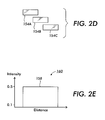
- the filtered beam 150 from the strip neutral density filter 102 is focused by the cylindrical lens 152 onto the facets 154A, 154B and 154C of the polygon mirror 156.
- the ROS 100 of the present application has an overfilled design so that the light beam 150 will illuminate more than one facet.
- the cylindrical lens 152 creates a focused beam 150 in the cross-scan plane at the polygon mirror 156, while maintaining the collimation of the beam 150 in the perpendicular or scan plane.
- the collimated uniform intensity beam 150 has a width in the scan direction, which will overfill a single facet and illuminate facets 154A, 154B and 154C in sequence.
- Facet 154A is shown for illustrative purposes as the imaging facet that reflects the light beam towards the photosensitive medium, while facets 154B and 154C are adjacent facets which will reflect the light beam 150 as the polygon mirror 156 rotates.
- the filtered intensity profile 124 of Figure 2c will be reflected and convolve from overfilled facets 154A, 154B and 154C of Figure 2d in sequence to form a flat intensity profile 158 of Figure 2e for the light beam 160 upon reflection from the polygon mirror 156 and at the photosensitive medium.
- Lens assembly 162 includes either a toroidal f-theta lens pair 164 and 166 or a non-toroidal f-theta lens plus a cylinder mirror (not shown).
- the f-theta lens assembly 160 focuses the light beam 158 to a generally circular spot 168 with a generally uniform intensity profile 158 on the scan line 170 of the photosensitive medium 172.
- the rotating overfilled facets of the polygon mirror 158 cause the spot 168 to sweep across the photosensitive medium 172 forming a succession of scan lines.
- the scan line 170 lies in the fast scan direction.
- photosensitive medium 172 moves in a slow scan direction, substantially perpendicular to the fast scan direction,. Movement in the slow scan direction is such that successive rotating overfilled facets of the polygon 158 form successive scan lines that are offset from each other in the slow scan direction.
- the light beam scans the photoesensitive medium with a plurality of scan lines in a raster scanning pattern such that individual picture elements ("pixels") of the image represented by the video data signals form a latent image on the photosensitive medium, which can then be developed and transferred to an appropriate image receiving medium such as paper.
- pixels picture elements
- the Gaussian intensity beam profile 110 of light beam 106 has a power uniformity falloff of 10.5 percent across the photosensitive medium while the filtered intensity profile 124 of the filtered light beam 150 from the strip neutral density filter 102 after reflection from the overfilled facets has a power uniformity falloff of 1.4 percent across the photosensitive medium.
- the strip neutral density filter 102 creates a more uniform intensity profile light beam for the overfilled ROS 100 of the present invention.
- the laser source 104, the collimating lens 108, the strip neutral density filter 102 and the cylindrical lens 152 form the pre-polygon optics.
- the strip neutral density filter 102 filters the stationary light beam 106 between the light source 104 and the rotating polygon mirror 158.
- F-theta lenses 162 are designed to provide a linear relationship between the rotation of polygon mirror 158 and the deflection of the scanned beam 160 in the scan direction onto the scan line 170 of the photosensitive medium 172.
Landscapes
- Physics & Mathematics (AREA)
- General Physics & Mathematics (AREA)
- Optics & Photonics (AREA)
- Mechanical Optical Scanning Systems (AREA)
- Facsimile Scanning Arrangements (AREA)
- Laser Beam Printer (AREA)
- Optical Elements Other Than Lenses (AREA)
- Facsimile Heads (AREA)
Applications Claiming Priority (2)
| Application Number | Priority Date | Filing Date | Title |
|---|---|---|---|
| US961779 | 1992-10-15 | ||
| US09/961,779 US20030058333A1 (en) | 2001-09-24 | 2001-09-24 | Strip neutral density filter for correcting intensity non-uniformity in a raster output scanning system |
Publications (2)
| Publication Number | Publication Date |
|---|---|
| EP1300699A2 true EP1300699A2 (fr) | 2003-04-09 |
| EP1300699A3 EP1300699A3 (fr) | 2003-11-12 |
Family
ID=25504987
Family Applications (1)
| Application Number | Title | Priority Date | Filing Date |
|---|---|---|---|
| EP02021398A Withdrawn EP1300699A3 (fr) | 2001-09-24 | 2002-09-24 | Filtre à densité neutre sous forme de bande pour améliorer l'uniformité d'intensité lumineuse dans un système de balayage de trames de sortie |
Country Status (4)
| Country | Link |
|---|---|
| US (1) | US20030058333A1 (fr) |
| EP (1) | EP1300699A3 (fr) |
| JP (1) | JP2003195211A (fr) |
| BR (1) | BR0203817A (fr) |
Families Citing this family (3)
| Publication number | Priority date | Publication date | Assignee | Title |
|---|---|---|---|---|
| US6847389B2 (en) * | 2003-05-02 | 2005-01-25 | Kabushiki Kaisha Toshiba | Optical beam scanning device and image forming apparatus |
| WO2005078511A1 (fr) * | 2004-02-04 | 2005-08-25 | Microvision, Inc. | Affichage frontal a balayage et systemes et procedes associes |
| JP2006267712A (ja) * | 2005-03-24 | 2006-10-05 | Fuji Xerox Co Ltd | 光走査装置及び画像形成装置 |
Family Cites Families (6)
| Publication number | Priority date | Publication date | Assignee | Title |
|---|---|---|---|---|
| US3558208A (en) * | 1967-10-11 | 1971-01-26 | Rca Corp | Optical compensating filter with selective radial absorption distribution |
| US5331468A (en) * | 1992-11-27 | 1994-07-19 | Eastman Kodak Company | Intensity redistribution for exposure correction in an overfilled symmetrical laser printer |
| US5539441A (en) * | 1993-11-09 | 1996-07-23 | Xerox Corporation | Jitter reduction in an overfilled raster output polygon scanner system |
| JP3417101B2 (ja) * | 1994-12-12 | 2003-06-16 | 富士ゼロックス株式会社 | 光学走査装置 |
| JPH10213767A (ja) * | 1997-01-29 | 1998-08-11 | Fuji Xerox Co Ltd | 光学走査装置 |
| JP3627453B2 (ja) * | 1997-06-25 | 2005-03-09 | 富士ゼロックス株式会社 | 光学走査装置 |
-
2001
- 2001-09-24 US US09/961,779 patent/US20030058333A1/en not_active Abandoned
-
2002
- 2002-09-19 JP JP2002272513A patent/JP2003195211A/ja not_active Withdrawn
- 2002-09-20 BR BR0203817-0A patent/BR0203817A/pt not_active Application Discontinuation
- 2002-09-24 EP EP02021398A patent/EP1300699A3/fr not_active Withdrawn
Also Published As
| Publication number | Publication date |
|---|---|
| EP1300699A3 (fr) | 2003-11-12 |
| BR0203817A (pt) | 2003-06-03 |
| JP2003195211A (ja) | 2003-07-09 |
| US20030058333A1 (en) | 2003-03-27 |
Similar Documents
| Publication | Publication Date | Title |
|---|---|---|
| EP0016630B1 (fr) | Dispositif de balayage optique | |
| EP0660578B1 (fr) | Procédé et dispositif pour la correction d'erreurs cycliques de positionement utilisant un dispositif de balayage de trames de sortie avec polygone à rayon modulable et optiques entièrement sphériques | |
| CA2327059C (fr) | Elements optiques de correction de vobulation multiple pour reduire la hauteur du systeme de balayage de sortie de matrice (ros) | |
| US5550668A (en) | Multispot polygon ROS with maximized line separation depth of focus | |
| EP1014149A1 (fr) | Dispositif de balayage à trame | |
| US5539441A (en) | Jitter reduction in an overfilled raster output polygon scanner system | |
| EP1014148B1 (fr) | Balayeur de réproduction avec un miroir polygonal illuminé totalement et des éléments optiques cylindriques | |
| EP0315428A2 (fr) | Système de balayage à polygone avec des rayons multiples | |
| US5400133A (en) | Alignment method and apparatus for optical imaging systems | |
| EP0599542B1 (fr) | Système électique deux éléments pour la compensation d'aberration focus dans des systèmes de balayage à laser | |
| EP1300699A2 (fr) | Filtre à densité neutre sous forme de bande pour améliorer l'uniformité d'intensité lumineuse dans un système de balayage de trames de sortie | |
| EP0843192B1 (fr) | Système de balayage optique | |
| EP0637770B1 (fr) | Système de balayage de trame compact pour formation d'image | |
| JP4817668B2 (ja) | 光走査装置 | |
| EP0575988A1 (fr) | Système de balayage à miroir polygonal illuminé totalement d'une manière symmétrique | |
| US5270849A (en) | Prevention of stray light reflections in a raster output scanner (ROS) using an overfilled polygon design | |
| US6067182A (en) | Optical scanning device | |
| JP2004020607A (ja) | 光走査装置及びそれを用いた画像形成装置 | |
| US6570696B2 (en) | Optical system for scanning and optical scanning apparatus | |
| JPH07174996A (ja) | ラスター出力スキャナーイメージシステム | |
| JPS61186921A (ja) | 光ビ−ム走査装置 | |
| JPH08220457A (ja) | 光走査装置 | |
| JPH02129614A (ja) | 光走査装置 | |
| JPH05232394A (ja) | 光走査装置 | |
| JP2002267965A (ja) | 光走査装置 |
Legal Events
| Date | Code | Title | Description |
|---|---|---|---|
| PUAI | Public reference made under article 153(3) epc to a published international application that has entered the european phase |
Free format text: ORIGINAL CODE: 0009012 |
|
| AK | Designated contracting states |
Kind code of ref document: A2 Designated state(s): AT BE BG CH CY CZ DE DK EE ES FI FR GB GR IE IT LI LU MC NL PT SE SK TR Designated state(s): AT BE BG CH CY CZ DE DK EE ES FI FR GB GR IE IT LI LU MC NL PT SE SK TR |
|
| AX | Request for extension of the european patent |
Extension state: AL LT LV MK RO SI |
|
| PUAL | Search report despatched |
Free format text: ORIGINAL CODE: 0009013 |
|
| AK | Designated contracting states |
Kind code of ref document: A3 Designated state(s): AT BE BG CH CY CZ DE DK EE ES FI FR GB GR IE IT LI LU MC NL PT SE SK TR |
|
| AX | Request for extension of the european patent |
Extension state: AL LT LV MK RO SI |
|
| AKX | Designation fees paid | ||
| REG | Reference to a national code |
Ref country code: DE Ref legal event code: 8566 |
|
| STAA | Information on the status of an ep patent application or granted ep patent |
Free format text: STATUS: THE APPLICATION IS DEEMED TO BE WITHDRAWN |
|
| 18D | Application deemed to be withdrawn |
Effective date: 20040513 |