EP1300710A2 - Steckerstift mit wenigstens einer Faserbohrung für einen optischen Multiplexer/Demultiplexer - Google Patents
Steckerstift mit wenigstens einer Faserbohrung für einen optischen Multiplexer/Demultiplexer Download PDFInfo
- Publication number
- EP1300710A2 EP1300710A2 EP01310794A EP01310794A EP1300710A2 EP 1300710 A2 EP1300710 A2 EP 1300710A2 EP 01310794 A EP01310794 A EP 01310794A EP 01310794 A EP01310794 A EP 01310794A EP 1300710 A2 EP1300710 A2 EP 1300710A2
- Authority
- EP
- European Patent Office
- Prior art keywords
- ferrule
- optical
- fiber
- optical multiplexer
- demultiplexer
- Prior art date
- Legal status (The legal status is an assumption and is not a legal conclusion. Google has not performed a legal analysis and makes no representation as to the accuracy of the status listed.)
- Withdrawn
Links
Images




Classifications
-
- G—PHYSICS
- G02—OPTICS
- G02B—OPTICAL ELEMENTS, SYSTEMS OR APPARATUS
- G02B6/00—Light guides; Structural details of arrangements comprising light guides and other optical elements, e.g. couplings
- G02B6/24—Coupling light guides
- G02B6/36—Mechanical coupling means
- G02B6/38—Mechanical coupling means having fibre to fibre mating means
- G02B6/3807—Dismountable connectors, i.e. comprising plugs
- G02B6/3833—Details of mounting fibres in ferrules; Assembly methods; Manufacture
- G02B6/3865—Details of mounting fibres in ferrules; Assembly methods; Manufacture fabricated by using moulding techniques
-
- G—PHYSICS
- G02—OPTICS
- G02B—OPTICAL ELEMENTS, SYSTEMS OR APPARATUS
- G02B6/00—Light guides; Structural details of arrangements comprising light guides and other optical elements, e.g. couplings
- G02B6/24—Coupling light guides
- G02B6/26—Optical coupling means
- G02B6/27—Optical coupling means with polarisation selective and adjusting means
- G02B6/2726—Optical coupling means with polarisation selective and adjusting means in or on light guides, e.g. polarisation means assembled in a light guide
- G02B6/274—Optical coupling means with polarisation selective and adjusting means in or on light guides, e.g. polarisation means assembled in a light guide based on light guide birefringence, e.g. due to coupling between light guides
-
- G—PHYSICS
- G02—OPTICS
- G02B—OPTICAL ELEMENTS, SYSTEMS OR APPARATUS
- G02B6/00—Light guides; Structural details of arrangements comprising light guides and other optical elements, e.g. couplings
- G02B6/24—Coupling light guides
- G02B6/26—Optical coupling means
- G02B6/28—Optical coupling means having data bus means, i.e. plural waveguides interconnected and providing an inherently bidirectional system by mixing and splitting signals
- G02B6/293—Optical coupling means having data bus means, i.e. plural waveguides interconnected and providing an inherently bidirectional system by mixing and splitting signals with wavelength selective means
- G02B6/29302—Optical coupling means having data bus means, i.e. plural waveguides interconnected and providing an inherently bidirectional system by mixing and splitting signals with wavelength selective means based on birefringence or polarisation, e.g. wavelength dependent birefringence, polarisation interferometers
-
- G—PHYSICS
- G02—OPTICS
- G02B—OPTICAL ELEMENTS, SYSTEMS OR APPARATUS
- G02B6/00—Light guides; Structural details of arrangements comprising light guides and other optical elements, e.g. couplings
- G02B6/24—Coupling light guides
- G02B6/26—Optical coupling means
- G02B6/28—Optical coupling means having data bus means, i.e. plural waveguides interconnected and providing an inherently bidirectional system by mixing and splitting signals
- G02B6/293—Optical coupling means having data bus means, i.e. plural waveguides interconnected and providing an inherently bidirectional system by mixing and splitting signals with wavelength selective means
- G02B6/29379—Optical coupling means having data bus means, i.e. plural waveguides interconnected and providing an inherently bidirectional system by mixing and splitting signals with wavelength selective means characterised by the function or use of the complete device
- G02B6/2938—Optical coupling means having data bus means, i.e. plural waveguides interconnected and providing an inherently bidirectional system by mixing and splitting signals with wavelength selective means characterised by the function or use of the complete device for multiplexing or demultiplexing, i.e. combining or separating wavelengths, e.g. 1xN, NxM
-
- G—PHYSICS
- G02—OPTICS
- G02B—OPTICAL ELEMENTS, SYSTEMS OR APPARATUS
- G02B6/00—Light guides; Structural details of arrangements comprising light guides and other optical elements, e.g. couplings
- G02B6/24—Coupling light guides
- G02B6/36—Mechanical coupling means
- G02B6/38—Mechanical coupling means having fibre to fibre mating means
- G02B6/3807—Dismountable connectors, i.e. comprising plugs
- G02B6/3833—Details of mounting fibres in ferrules; Assembly methods; Manufacture
- G02B6/3834—Means for centering or aligning the light guide within the ferrule
-
- G—PHYSICS
- G02—OPTICS
- G02B—OPTICAL ELEMENTS, SYSTEMS OR APPARATUS
- G02B6/00—Light guides; Structural details of arrangements comprising light guides and other optical elements, e.g. couplings
- G02B6/24—Coupling light guides
- G02B6/36—Mechanical coupling means
- G02B6/38—Mechanical coupling means having fibre to fibre mating means
- G02B6/3807—Dismountable connectors, i.e. comprising plugs
- G02B6/3833—Details of mounting fibres in ferrules; Assembly methods; Manufacture
- G02B6/3851—Ferrules having keying or coding means
-
- G—PHYSICS
- G02—OPTICS
- G02B—OPTICAL ELEMENTS, SYSTEMS OR APPARATUS
- G02B6/00—Light guides; Structural details of arrangements comprising light guides and other optical elements, e.g. couplings
- G02B6/24—Coupling light guides
- G02B6/26—Optical coupling means
- G02B6/27—Optical coupling means with polarisation selective and adjusting means
- G02B6/2706—Optical coupling means with polarisation selective and adjusting means as bulk elements, i.e. free space arrangements external to a light guide, e.g. polarising beam splitters
- G02B6/2713—Optical coupling means with polarisation selective and adjusting means as bulk elements, i.e. free space arrangements external to a light guide, e.g. polarising beam splitters cascade of polarisation selective or adjusting operations
- G02B6/272—Optical coupling means with polarisation selective and adjusting means as bulk elements, i.e. free space arrangements external to a light guide, e.g. polarising beam splitters cascade of polarisation selective or adjusting operations comprising polarisation means for beam splitting and combining
-
- G—PHYSICS
- G02—OPTICS
- G02B—OPTICAL ELEMENTS, SYSTEMS OR APPARATUS
- G02B6/00—Light guides; Structural details of arrangements comprising light guides and other optical elements, e.g. couplings
- G02B6/24—Coupling light guides
- G02B6/26—Optical coupling means
- G02B6/27—Optical coupling means with polarisation selective and adjusting means
- G02B6/2746—Optical coupling means with polarisation selective and adjusting means comprising non-reciprocal devices, e.g. isolators, FRM, circulators, quasi-isolators
-
- G—PHYSICS
- G02—OPTICS
- G02B—OPTICAL ELEMENTS, SYSTEMS OR APPARATUS
- G02B6/00—Light guides; Structural details of arrangements comprising light guides and other optical elements, e.g. couplings
- G02B6/24—Coupling light guides
- G02B6/36—Mechanical coupling means
- G02B6/38—Mechanical coupling means having fibre to fibre mating means
- G02B6/3807—Dismountable connectors, i.e. comprising plugs
- G02B6/381—Dismountable connectors, i.e. comprising plugs of the ferrule type, e.g. fibre ends embedded in ferrules, connecting a pair of fibres
- G02B6/3812—Dismountable connectors, i.e. comprising plugs of the ferrule type, e.g. fibre ends embedded in ferrules, connecting a pair of fibres having polarisation-maintaining light guides
-
- G—PHYSICS
- G02—OPTICS
- G02B—OPTICAL ELEMENTS, SYSTEMS OR APPARATUS
- G02B6/00—Light guides; Structural details of arrangements comprising light guides and other optical elements, e.g. couplings
- G02B6/24—Coupling light guides
- G02B6/36—Mechanical coupling means
- G02B6/38—Mechanical coupling means having fibre to fibre mating means
- G02B6/3807—Dismountable connectors, i.e. comprising plugs
- G02B6/381—Dismountable connectors, i.e. comprising plugs of the ferrule type, e.g. fibre ends embedded in ferrules, connecting a pair of fibres
- G02B6/3818—Dismountable connectors, i.e. comprising plugs of the ferrule type, e.g. fibre ends embedded in ferrules, connecting a pair of fibres of a low-reflection-loss type
- G02B6/3822—Dismountable connectors, i.e. comprising plugs of the ferrule type, e.g. fibre ends embedded in ferrules, connecting a pair of fibres of a low-reflection-loss type with beveled fibre ends
-
- G—PHYSICS
- G02—OPTICS
- G02B—OPTICAL ELEMENTS, SYSTEMS OR APPARATUS
- G02B6/00—Light guides; Structural details of arrangements comprising light guides and other optical elements, e.g. couplings
- G02B6/24—Coupling light guides
- G02B6/36—Mechanical coupling means
- G02B6/38—Mechanical coupling means having fibre to fibre mating means
- G02B6/3807—Dismountable connectors, i.e. comprising plugs
- G02B6/3833—Details of mounting fibres in ferrules; Assembly methods; Manufacture
- G02B6/3834—Means for centering or aligning the light guide within the ferrule
- G02B6/3835—Means for centering or aligning the light guide within the ferrule using discs, bushings or the like
- G02B6/3837—Means for centering or aligning the light guide within the ferrule using discs, bushings or the like forwarding or threading methods of light guides into apertures of ferrule centering means
-
- G—PHYSICS
- G02—OPTICS
- G02B—OPTICAL ELEMENTS, SYSTEMS OR APPARATUS
- G02B6/00—Light guides; Structural details of arrangements comprising light guides and other optical elements, e.g. couplings
- G02B6/24—Coupling light guides
- G02B6/36—Mechanical coupling means
- G02B6/38—Mechanical coupling means having fibre to fibre mating means
- G02B6/3807—Dismountable connectors, i.e. comprising plugs
- G02B6/3869—Mounting ferrules to connector body, i.e. plugs
Definitions
- the present invention relates to an optical multiplexer/demultiplexer for use in optical communications and optical measuring.
- a capillary for fixing an optical fiber is formed of glass or zirconia.
- a glass capillary is produced by drawing heated glass and cutting it. A wire is put through a fiber hole of the capillary, then an abrasive is fed there to polish inside and the outside of the capillary is ground to yield a predetermined standardized product. A zirconia capillary after sintering is pressed into a part, thereby yielding a ferrule. To provide a predetermined standardized product, the zirconia capillary is subjected to the same treatments as the glass capillary undergoes.
- an optical multiplexer/demultiplexer has a capillary produced in the above-described manner, the processing takes time and labors, making the ferrule expensive, disadvantageously.
- the fiber hole of the capillary is polished, when there are plural fiber holes, it is hard to achieve parallelism between the fiber holes.
- an optical multiplexer/demultiplexer assembled with a ferrule using such a capillary the directions of beams incident to light incident fibers or the directions of beams outputting from light output fibers differ from one another. This leads to a large coupling loss to other optical components.
- a capillary may be used in an optical multiplexer/demultiplexer in which a plurality of fiber holes, e.g., two fiber holes, laid side by side with the pitch between the fiber holes set to the diameter of an optical fiber and lights outputting from both optical fibers are incident to an optical filter via a lens.
- a plurality of fiber holes e.g., two fiber holes, laid side by side with the pitch between the fiber holes set to the diameter of an optical fiber and lights outputting from both optical fibers are incident to an optical filter via a lens.
- the optical axes of the two optical fibers are shifted from the center of the capillary and thus from the optical axis of the lens, the incident angle of the beam that enters the optical filter through the lens becomes large, thus increasing a PDL (Polarization Dependent Loss).
- the focal length of the lens is 1.8 mm, for example, the angle of incidence to the optical filter becomes 4 degrees.
- an object of the present invention to provide an optical multiplexer/demultiplexer which allows a fiber hole to be formed with a high precision and can suppress a PDL to a low level.
- an optical multiplexer/demultiplexer wherein an optical fiber, attached to a ferrule, for receiving and outputting light, a lens member and an optical component are optically coupled, the ferrule being formed of a synthetic resin and having at least one fiber hole formed therein.
- FIGS. 1A through 21 One embodiment of an optical multiplexer/demultiplexer according to the present invention will now be described in detail with reference to FIGS. 1A through 21.
- An optical multiplexer/demultiplexer 1 has a first ferrule 2, an optical component 3, a lens 4 and a second ferrule 5 as shown in FIG. 1A.
- the first ferrule 2 is a singlefiber ferrule to which a single optical fiber 2a is attached, and is formed of a synthetic resin, such as a thermoplastic epoxy resin, or engineering plastics such as a thermosetting polyphenylene sulfide (PPS), or engineering plastics having a low mold shrinkage of 1.0% or less obtained by allowing the former engineering plastics to contain a filler, such as at least 60% by weight of silica or metal oxide, by a molding method, such as insert molding, transfer molding or injection molding.
- a synthetic resin such as a thermoplastic epoxy resin, or engineering plastics such as a thermosetting polyphenylene sulfide (PPS), or engineering plastics having a low mold shrinkage of 1.0% or less obtained by allowing the former engineering plastics to contain a filler, such as at least 60% by weight of silica or metal oxide, by a molding method, such as insert molding, transfer molding or injection molding.
- the optical component 3 is, for example, a narrowband pass filter comprising a dielectric multilayer coating having the maximum transmittance at a specific wavelength and is designed to be able to make the PDL smaller as the incident angle approaches 0° or as the incident angle to the filter approaches 0°.
- the optical component 3 may be a birefringent crystal plate, a Faraday rotator, a ⁇ /2 wave plate or the like.
- the lens 4 is, for example, an aspherical lens having a focal length of about 1.8 mm. Though not shown in FIG. 1A, a lens having the same function as the lens 4 may be provided between the first ferrule 2 and the optical component 3.
- the second ferrule 5 has optical fibers 5a and 5b which are laid out with a pitch of 127 ⁇ m therebetween so that the incident angle of light incident to the optical component 3 approaches as close to 0° as possible.
- the position of the second ferrule 5 is adjusted in such a way that the optical fiber 5a is positioned on the same axis as the optical fiber 2a.
- the second ferrule 5 is formed of a synthetic resin.
- the optical multiplexer/demultiplexer 1 constructed in the above-described manner may serve as a demultiplexer which functions in such a way that when wavelength-multiplexed light consisting of lights of multiple wavelengths transmitted through the optical fiber 5a is condensed by the lens 4 and is led to the optical component 3, the optical component 3 passes light of a specific wavelength and reflects lights of other wavelengths, and the reflected lights are condensed again by the lens 4 and led out to the optical fiber 5b.
- the optical multiplexer/demultiplexer 1 also functions as a multiplexer, where a light of a specific wavelength (wavelength ⁇ 1) out of the wavelength-multiplexed light transmitted through the optical fiber 2a of the first ferrule 2 is transmitted through the optical component 3, and a light (wavelength ⁇ 2) transmitted through the optical fiber 5b is reflected by the optical component 3, so that both lights are multiplexed and go out of the optical fiber 5a as a light having wavelengths ⁇ 1, ⁇ 2.
- the first and second ferrules 2 and 5 unlike those in the optical multiplexer/demultiplexer of the related art, do not use glass or zirconia capillary and are formed of a synthetic resin. Therefore, the fiber holes of the optical fibers 2a and 5a of the first and second ferrules 2 and 5 can be formed with a high precision, so that the optical axes of the optical fibers 2a and 5a are not deviated from the optical axis of the lens 4. This can reduce the incident angle of light entering the optical component 3 through the lens 4, thereby suppressing the PDL of the optical multiplexer/demultiplexer 1 at a low level.
- the optical component 3 comprises, for example, birefringent crystal plates 3a to 3c, Faraday rotators 3d and 3e and ⁇ /2 wave plates 3f and 3g and lens 4a and 4b are used in place of the lens 4, as shown in FIG. 1B.
- This structure can allow the optical multiplexer/demultiplexer 1 to serve as an optical circulator which emits light coming from the optical fiber 5a to the optical fiber 2a and emits light coming from the optical fiber 2a to the optical fiber 5b.
- a prism which changes the optical path may be arranged between the lens 4b on that side of the second ferrule 5 and the birefringent crystal plate 3c.
- the ferrule used in the optical multiplexer/demultiplexer 1 of the present invention is formed of a synthetic resin and should have at least one fiber hole. Therefore, various ferrules which will be discussed hereinunder can be used.
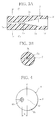
- three fiber holes 7b and guide holes 7d linked to the fiber holes 7b via tapered holes 7c are formed in a cylindrical body 7a of a ferrule 7 shown in FIG. 2 and FIGS. 3A and 3B in the lengthwise direction.
- the ferrule 7 has a front face 7e which is an end face on that side where the fiber holes 7b are provided, and a rear face 7f which is an end face on that side where the guide holes 7d are provided.
- Optical fibers are to be inserted in the rear face 7f. It is to be noted that the ferrule has only to have at least one fiber hole 7b together with its associated single tapered hole 7c and single guide hole 7d.
- the ferrule 7 is formed of a synthetic resin, such as a thermoplastic epoxy resin, or engineering plastics such as a thermosetting polyphenylene sulfide (PPS), or engineering plastics having a low mold shrinkage of 1.0% or less obtained by allowing the former engineering plastics to contain a filler, such as at least 60% by weight of silica or metal oxide, by a molding method, such as insert molding, transfer molding or injection molding.
- a synthetic resin such as a thermoplastic epoxy resin, or engineering plastics such as a thermosetting polyphenylene sulfide (PPS), or engineering plastics having a low mold shrinkage of 1.0% or less obtained by allowing the former engineering plastics to contain a filler, such as at least 60% by weight of silica or metal oxide, by a molding method, such as insert molding, transfer molding or injection molding.
- a transparent or semitransparent one is used for the ferrule 7.
- the use of this material is preferable as a worker can conduct a work of inserting an optical fiber into the fiber hole 7b through the guide hole 7d and securely adhering it while visually observing the work at the time of assembling the optical multiplexer/demultiplexer.
- the ferrule 7 may have its outer surface plated with nickel, nickel-chromium-gold, nickel-gold or the like. Such plating is preferable as it can allow the ferrule 7 to be soldered.
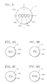
- the X axis and Y axis perpendicular to each other are set as illustrated with the center of a body 8a being the original point O.
- the ferrule 8 and a lens located apart from the ferrule 8 by a predetermined distance are set in such a way that the center of the fiber hole 8b and the optical axis of the lens pass the original point O and lies on the axis perpendicular to the sheet of FIG. 4.
- the optical multiplexer/demultiplexer using the ferrule 8 is ideal in that entering and outputting of a beam which is transmitted through an optical fiber (not shown) securely adhered into the fiber hole 8b and outputs from the optical fiber and a beam which enters the optical fiber from outside take place on the same axis.
- the fiber hole 8b of the ferrule 8 is offset adequately from the original point O in FIG. 4 so that a beam can enter and output from the optical fiber at a desirable angle.
- the ferrule is formed in such a way as to be a ferrule 9 shown in FIG. 5 or a ferrule 10 shown in FIG. 6.
- a fiber hole 9b1 is formed at the position of the original point O and a fiber hole 9b2 is formed at a position offset by a distance W12 from the center of the fiber hole 9b1.
- the degree of parallelization of the fiber holes 9b1 and 9b2 is set to 3 or smaller.
- fiber holes 10b1 and 10b2 are formed at symmetrical positions with respect to the original point O.
- the distance W12 between the fiber holes 10b1 and 10b2 takes an arbitrary value, and the degree of parallelization of the fiber holes 10b1 and 10b2 is set to 3 or smaller as in the previous case.
- the ferrule is formed like a ferrule 11 shown in FIG. 7.
- a fiber hole 11b1 is formed at the position of the original point O and fiber holes 11b2 and 11b3 are formed at positions symmetrical to each other with respect to the original point O and adjacent to the fiber hole 11b1.
- the degree of parallelization of the fiber holes 1 to 11b3 is set to 3 or smaller.
- the ferrule is formed like a ferrule 12 shown in FIG. 8.
- fiber holes 12b1 and 12b2 are formed adjacent and symmetrical to each other with respect to the original point O and fiber holes 12b3 and 12b4 are formed at positions outside and adjacent to the fiber holes 12b1 and 12b2 and symmetrical to each other with respect to the original point O.
- the degree of parallelization of the fiber holes 12b1 to 12b4 is set to 3 or smaller.
- the ferrule to be used in the optical multiplexer/demultiplexer 1 of the present invention has an odd number of fiber holes as a total
- the other fiber holes are formed at positions symmetrical to one another with respect to the original point O.
- all the fiber holes are formed at positions symmetrical to one another with respect to the original point O.
- the fiber holes may be formed like a rectangular fiber hole 13b of a ferrule 13 shown in FIG. 9A which is large enough to retain two optical fibers, or may be formed like an elongated fiber hole 13b with rounded corners shown in FIG. 9B which is equivalent to two fiber holes joined together.
- the fiber holes may be formed like an ellipsoidal fiber hole 13b shown in FIG. 9C which is so designed that two optical fibers are insertable, or may be formed like a center-dented elongated fiber hole 13b shown in FIG. 9D which is acquired by joining two fiber holes located apart from each other by a predetermined distance.
- a step 14g is formed in a front face 14e of a body 14a as in a ferrule 14 shown in FIG. 10.
- the step 14g of the ferrule 14 used as a marking one can easily see the layout direction of a plurality of optical fiber holes 14b, i.e., the layout direction of a plurality of optical fibers that are securely adhered into the fiber holes 14b.
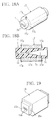
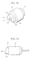
- the ferrule 14 may be provided on its outer surface with a metal jacket 20 as shown in FIG. 20.
- the jacket 20 is formed into a cylinder having a ferrule hole 20a by metal injection and is provided to attach the ferrule 14 to another member by soldering or welding using a YAG laser or the like.
- an alloy such as a copper-tungsten alloy, stainless steel (SUS 304), nickel-iron-cobalt alloy, besides a metal, such as aluminum, copper or tungsten, is used for the jacket 20.
- Soldering becomes easier if the surface of the jacket 20 is plated with nickel, nickel-chromium-gold, nickel-gold or the like.
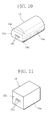
- the ferrule for use in the optical multiplexer/demultiplexer 1 of the present invention may be constructed like a ferrule 15 shown in FIG. 11 in such a way that a body 15a is formed into a quadratic prism and plural fiber holes 15b, for example, three fiber holes, and unillustrated plural (e.g., three) guide holes which are linked to the fiber holes 15b via tapered holes (not shown) are formed in the body 15a in the lengthwise direction.
- plural fiber holes 15b for example, three fiber holes, and unillustrated plural (e.g., three) guide holes which are linked to the fiber holes 15b via tapered holes (not shown) are formed in the body 15a in the lengthwise direction.
- the ferrule 15 with the above-described structure is formed of the aforementioned engineering plastics by a molding method, such as insert molding, transfer molding or injection molding
- optical fibers are secured into the fiber holes 15b by an adhesive and the front end face of the ferrule 15, together with the end faces of the optical fibers, is subjected to optical polishing, thus yielding the optical multiplexer/demultiplexer.
- an optical coating such as an anti-reflection coating or a wavelength selecting coating, with respect to air or the adhesive may be formed on a front face 15e of the ferrule 15 together with the end faces of the optical fibers.
- a front face 16e of a body 16a is polished obliquely.
- the use of the thus constituted ferrule 16 can prevent a return loss which is originated from reflection of light transmitted through each optical fiber at the front face 16e.
- ferrule 16 is provided on its outer surface with a metal jacket 21 having a structure similar to that of the jacket 20, as shown in FIG. 21, it becomes easy to attach the ferrule 16 to another member by soldering or welding using a YAG laser or the like. Soldering becomes easier if the surface of the jacket 21 is plated with nickel, nickel-chromium-gold, nickel-gold or the like.
- available optical fibers to be secured to the ferrule include single-mode optical fibers, such as a polarization-maintaining single-mode optical fiber, a rare-earth-doped single-mode optical fiber and a rare-earth-doped polarization-maintaining single-mode optical fiber, as well as multi-mode optical fibers.
- single-mode optical fibers such as a polarization-maintaining single-mode optical fiber, a rare-earth-doped single-mode optical fiber and a rare-earth-doped polarization-maintaining single-mode optical fiber, as well as multi-mode optical fibers.
- a metal jacket 17 may be provided on the outer surface of the ferrule to be used in the optical multiplexer/demultiplexer 1 of the present invention, like the ferrule 7 shown in FIG. 2.
- the jacket 17 is formed into a cylinder having a ferrule hole 17a by metal injection and is provided to attach the ferrule 7 to another member by soldering or welding using a YAG laser or the like.
- an alloy such as a copper-tungsten alloy, stainless steel (SUS 304), nickel-iron-cobalt alloy, besides a metal, such as aluminum, copper or tungsten, is used for the jacket 17.
- the ferrule 7 constructed in the above-described manner is manufactured by molding the aforementioned engineering plastics in the jacket 17.
- the ferrule 7 according to the embodiment is designed in such a way that grooves or recesses at least 0.005 mm deep, or projections or projecting stripes at least 0.005 mm high are formed in or on the inner surface of the fiber hole 17a of the jacket 17, or the inner face of the jacket 17 is made rough to have a maximum height (Ry) of at least 1 ⁇ m.
- This is a whirl-stop measure that prevents the jacket 17 from turning with respect to the ferrule 7 after production with respect to the shrinkage of the engineering plastics that constitutes the ferrule 7 or the expansion of the jacket 17.
- the structure provides a better whirl-stop measure for the ferrule 7 than the former whirl-stop measure.
- the recesses 17b, elliptical grooves 17c, V grooves 17d and projecting stripes 17e may be formed by one pitch spirally or intermittently in the lengthwise direction.
- the ferrule 7 according to the present embodiment may be formed in such a way that the cross-sectional shape of the ferrule hole 17a formed in the jacket 17 is formed into a polygonal shape, such as an ellipsis as shown in FIG. 15A, a hexagon as shown in FIG. 15B, or a star as shown in FIG. 15C, the whirl-stop measure of the jacket 17 with respect to the ferrule 7.
- the diameter of the ferrule hole 17a in the jacket 17 is changed in the lengthwise direction in such a way as to be smaller than the diameters of both ends of the ferrule 7 and constant in the lengthwise direction as shown in FIG. 16A or to be larger than the diameter of the ferrule 7 and become maximum at the middle as shown in FIG. 16B.
- This provides a disengagement stopping measure that prevents the jacket 17 from coming off the ferrule 7 after production with respect to the shrinkage of the engineering plastics that constitutes the ferrule 7 or the expansion of the jacket 17.
- grooves or recesses, or projections or projecting stripes as the aforementioned whirl-stop measure may be formed in or on the jacket 17 are formed in or on the inner surface of the jacket 17, or the inner face of the jacket 17 may be made rough to have a maximum height (Ry) of at least 1 ⁇ m.
- the jacket 17 is formed in such a way that the diameter of the ferrule hole 17a is smaller than the diameters of both ends of the ferrule 7 and constant in the lengthwise direction and a disengagement stopping groove 17g is radially formed in either lengthwise end of the jacket 17, it is possible to provide both effects of whirl-stopping and disengagement stopping of the jacket 17 with respect to the ferrule 7 as shown in Figs. 18A and 18B.
- the ferrule to be used in the optical multiplexer/demultiplexer 1 of the present invention may be provided on its outer surface with a metal jacket 18 with a rectangular cylindrical shape as shown in FIG. 11.
- the outer shape of the jacket may take a polygonal shape, such as a hexagonal shape, besides a rectangular shape.
Landscapes
- Physics & Mathematics (AREA)
- General Physics & Mathematics (AREA)
- Optics & Photonics (AREA)
- Optical Couplings Of Light Guides (AREA)
- Mechanical Coupling Of Light Guides (AREA)
Applications Claiming Priority (2)
| Application Number | Priority Date | Filing Date | Title |
|---|---|---|---|
| JP2001310351 | 2001-10-05 | ||
| JP2001310351 | 2001-10-05 |
Publications (2)
| Publication Number | Publication Date |
|---|---|
| EP1300710A2 true EP1300710A2 (de) | 2003-04-09 |
| EP1300710A3 EP1300710A3 (de) | 2004-08-18 |
Family
ID=19129340
Family Applications (1)
| Application Number | Title | Priority Date | Filing Date |
|---|---|---|---|
| EP01310794A Withdrawn EP1300710A3 (de) | 2001-10-05 | 2001-12-21 | Steckerstift mit wenigstens einer Faserbohrung für einen optischen Multiplexer/Demultiplexer |
Country Status (4)
| Country | Link |
|---|---|
| US (1) | US6744944B2 (de) |
| EP (1) | EP1300710A3 (de) |
| CN (1) | CN1412585A (de) |
| CA (1) | CA2365757A1 (de) |
Cited By (1)
| Publication number | Priority date | Publication date | Assignee | Title |
|---|---|---|---|---|
| WO2017037115A1 (de) * | 2015-08-31 | 2017-03-09 | Fraunhofer-Gesellschaft zur Förderung der angewandten Forschung e. V. | Herstellung eines faserkopplers |
Families Citing this family (13)
| Publication number | Priority date | Publication date | Assignee | Title |
|---|---|---|---|---|
| DE10106809A1 (de) * | 2001-02-14 | 2002-09-19 | Siemens Ag | Verfahren zur Herstellung eines Lochs in einem Körper, insbesondere eines Einspritzlochs in einem Kraftstoffinjektor |
| US7561769B2 (en) * | 2004-03-16 | 2009-07-14 | Sumitomo Electric Industries, Ltd. | Optical fiber for irradiation-light transfer and light irradiation device equipped with the same |
| JP2006058369A (ja) * | 2004-08-17 | 2006-03-02 | Sumitomo Electric Ind Ltd | 光部品とその接続方法、及び光モジュール |
| US7826697B2 (en) * | 2008-08-19 | 2010-11-02 | Olympus Corporation | System and method for asymmetrical fiber spacing for wavelength selective switches |
| WO2010068890A1 (en) * | 2008-12-11 | 2010-06-17 | Afl Telecommunications Llc | A "secured" fiber optic connecting system and method using offset fiber position in a single-fiber connector |
| US10545294B1 (en) * | 2019-07-08 | 2020-01-28 | Arrayed Fiberoptics Corporation | Microfabrication method for optical components |
| US9188745B2 (en) * | 2013-09-09 | 2015-11-17 | Panduit Corp. | Multi-channel, multi-port optical tap coupler |
| US9201197B2 (en) * | 2013-09-09 | 2015-12-01 | Panduit Corp. | Multi-channel, multi-port optical tap coupler |
| JP6780845B6 (ja) * | 2016-08-05 | 2020-12-09 | サンテック株式会社 | 検出装置 |
| US11333835B2 (en) | 2019-07-08 | 2022-05-17 | Arrayed Fiberoptics Corporation | Microfabrication method for optical components |
| CN115176183A (zh) * | 2020-02-28 | 2022-10-11 | 古河电气工业株式会社 | 光耦合器以及光输出装置 |
| US11852871B2 (en) * | 2022-05-04 | 2023-12-26 | Panduit Corp. | Short reach gap connector |
| CN115201968B (zh) * | 2022-06-14 | 2024-04-19 | 核工业理化工程研究院 | 一种光纤耦合器及其应用 |
Family Cites Families (22)
| Publication number | Priority date | Publication date | Assignee | Title |
|---|---|---|---|---|
| JPS60198509A (ja) * | 1984-03-22 | 1985-10-08 | Sumitomo Electric Ind Ltd | 光コネクタフエル−ルとその製造方法 |
| JPS6170521A (ja) * | 1984-09-14 | 1986-04-11 | Nec Corp | 光固定減衰器 |
| JPS61102609A (ja) * | 1984-10-25 | 1986-05-21 | Sumitomo Electric Ind Ltd | 光コネクタフエル−ル |
| US4989946A (en) * | 1989-01-19 | 1991-02-05 | Alcatel Na, Inc. | Fiber optic switch |
| US5390270A (en) * | 1989-11-28 | 1995-02-14 | Kel Corporation | Optical fiber ferrule assemblies |
| JP2996602B2 (ja) * | 1995-01-31 | 2000-01-11 | 株式会社精工技研 | 定偏波光ファイバ用光分岐結合器 |
| JP3124467B2 (ja) * | 1995-04-21 | 2001-01-15 | 株式会社精工技研 | 光カプラ |
| JPH09145957A (ja) * | 1995-11-20 | 1997-06-06 | Fujitsu Ltd | 光コネクタ |
| JPH09203815A (ja) * | 1996-01-29 | 1997-08-05 | Nippon Telegr & Teleph Corp <Ntt> | 偏波保持光ファイバの位置合せ方法および偏波保持光ファイバアレイ |
| US5751875A (en) * | 1996-10-04 | 1998-05-12 | The Whitaker Corporation | Optical fiber ferrule |
| EP1130435A1 (de) * | 1997-02-21 | 2001-09-05 | Nippon Telegraph and Telephone Corporation | Steckerstift aus Kunststoff für eine optische Steckverbindung |
| US6447173B1 (en) * | 1998-11-27 | 2002-09-10 | Murata Manufacturing Co., Ltd. | Ferrule for optical connector, metal article having a through-hole and manufacturing method therefor |
| US6498876B1 (en) * | 1999-02-22 | 2002-12-24 | Alliance Fiber Optics Products, Inc. | Multi-port fiber optic device with v-groove ferrule |
| US6389188B1 (en) * | 1999-02-23 | 2002-05-14 | Optical Coating Laboratory, Inc. | Hybrid wavelength selective optical router and switch |
| US6249625B1 (en) * | 1999-06-28 | 2001-06-19 | E-Tek Dynamics, Inc. | Fiberoptic devices with a joined optical fiber subassembly |
| JP2001051157A (ja) * | 1999-08-11 | 2001-02-23 | Kyocera Corp | 光ファイバ固定具およびその製造方法およびそれを用いた光ファイバコネクタ |
| JP2001100065A (ja) * | 1999-10-01 | 2001-04-13 | Ykk Corp | 光ファイバ一体型フェルール及びその製造方法 |
| DE19951470C2 (de) * | 1999-10-26 | 2002-09-26 | Inst Mikrotechnik Mainz Gmbh | Ferrule zur Aufnahme mindestens einer Glasfaser und Verfahren zu dessen Herstellung |
| JP2001183546A (ja) * | 1999-12-24 | 2001-07-06 | Furukawa Electric Co Ltd:The | 多心フェルール |
| US6582135B2 (en) * | 2000-06-22 | 2003-06-24 | Corning Incorporated | Method of matching optical elements and fiber ferrules |
| US6343166B1 (en) * | 2000-06-22 | 2002-01-29 | Corning Incorporated | Three-port filter and method of manufacture |
| JP2002174749A (ja) * | 2000-09-27 | 2002-06-21 | Kyoei Senzai Kk | 光ファイバ接続用コネクタの複合フェルール及びこのフェルールの製造方法並びにこのフェルールを用いた光ファイバ接続用コネクタ |
-
2001
- 2001-12-20 US US10/029,556 patent/US6744944B2/en not_active Expired - Fee Related
- 2001-12-21 EP EP01310794A patent/EP1300710A3/de not_active Withdrawn
- 2001-12-21 CA CA002365757A patent/CA2365757A1/en not_active Abandoned
- 2001-12-25 CN CN01143981.5A patent/CN1412585A/zh active Pending
Cited By (2)
| Publication number | Priority date | Publication date | Assignee | Title |
|---|---|---|---|---|
| WO2017037115A1 (de) * | 2015-08-31 | 2017-03-09 | Fraunhofer-Gesellschaft zur Förderung der angewandten Forschung e. V. | Herstellung eines faserkopplers |
| US11267210B2 (en) | 2015-08-31 | 2022-03-08 | Fraunhofer-Gesellschaft Der Angewandten Forschung E.V. | Production of a fiber coupler |
Also Published As
| Publication number | Publication date |
|---|---|
| CA2365757A1 (en) | 2003-04-05 |
| CN1412585A (zh) | 2003-04-23 |
| EP1300710A3 (de) | 2004-08-18 |
| US20030068121A1 (en) | 2003-04-10 |
| US6744944B2 (en) | 2004-06-01 |
Similar Documents
| Publication | Publication Date | Title |
|---|---|---|
| US11982848B2 (en) | Optical fiber-to-chip interconnection | |
| EP1300710A2 (de) | Steckerstift mit wenigstens einer Faserbohrung für einen optischen Multiplexer/Demultiplexer | |
| US6647184B2 (en) | Optical waveguide device and method of manufacturing the same | |
| US7474822B2 (en) | Optical fiber collimator | |
| DE19610881B4 (de) | Mikrosystembaustein | |
| TWI410688B (zh) | 光元件以及透鏡組件 | |
| CA3117589A1 (en) | Demountable edge couplers with micro-mirror optical bench for photonic integrated circuits | |
| US5692081A (en) | Four polarization maintaining optical fiber ferrule and optical coupler using same | |
| JP2023512606A (ja) | 弾性平均結合 | |
| JP2016095410A (ja) | グリンレンズアレイ、レンズ付きコネクタ、及びレンズ付きコネクタシステム | |
| WO2018221717A1 (ja) | 光コネクタおよび光コネクタ接続構造 | |
| US20040017982A1 (en) | Optical functioning component | |
| US9753221B2 (en) | Optical coupler for a multicore fiber | |
| KR20040015330A (ko) | 고전력 확장 광선 커넥터 및 그 고전력 확장 광선커넥터의 사용 방법과 제작 방법 | |
| EP1821123A1 (de) | Optischer Leistungsmonitor | |
| US20190072725A1 (en) | Optical connector ferrule | |
| US7194160B2 (en) | Filter module | |
| EP1457795B1 (de) | Optischer Kollimator | |
| US9229170B1 (en) | Two-port optical devices using mini-collimators | |
| US12416769B2 (en) | Optical fiber connection component and method for manufacturing optical fiber connection component | |
| US12013579B1 (en) | Optical interconnect devices | |
| US20020126955A1 (en) | Optical filtering module and optical devices using such optical filtering module | |
| JP2003177277A (ja) | 光結合モジュール | |
| JP2001004863A (ja) | ロッドレンズ付き光ファイバ配列部品とその製造方法 | |
| US20250180819A1 (en) | Optical connectors with polarization-maintaining fibers |
Legal Events
| Date | Code | Title | Description |
|---|---|---|---|
| PUAI | Public reference made under article 153(3) epc to a published international application that has entered the european phase |
Free format text: ORIGINAL CODE: 0009012 |
|
| AK | Designated contracting states |
Kind code of ref document: A2 Designated state(s): AT BE CH CY DE DK ES FI FR GB GR IE IT LI LU MC NL PT SE TR Designated state(s): AT BE CH CY DE DK ES FI FR GB GR IE IT LI LU MC NL PT SE TR |
|
| AX | Request for extension of the european patent |
Extension state: AL LT LV MK RO SI |
|
| PUAL | Search report despatched |
Free format text: ORIGINAL CODE: 0009013 |
|
| AK | Designated contracting states |
Kind code of ref document: A3 Designated state(s): AT BE CH CY DE DK ES FI FR GB GR IE IT LI LU MC NL PT SE TR |
|
| AX | Request for extension of the european patent |
Extension state: AL LT LV MK RO SI |
|
| AKX | Designation fees paid | ||
| REG | Reference to a national code |
Ref country code: DE Ref legal event code: 8566 |
|
| STAA | Information on the status of an ep patent application or granted ep patent |
Free format text: STATUS: THE APPLICATION IS DEEMED TO BE WITHDRAWN |
|
| 18D | Application deemed to be withdrawn |
Effective date: 20050219 |