EP1300751A1 - Dispositif de commande de type levier - Google Patents
Dispositif de commande de type levier Download PDFInfo
- Publication number
- EP1300751A1 EP1300751A1 EP01904321A EP01904321A EP1300751A1 EP 1300751 A1 EP1300751 A1 EP 1300751A1 EP 01904321 A EP01904321 A EP 01904321A EP 01904321 A EP01904321 A EP 01904321A EP 1300751 A1 EP1300751 A1 EP 1300751A1
- Authority
- EP
- European Patent Office
- Prior art keywords
- lever
- spherical
- magnet
- magnetic
- operating device
- Prior art date
- Legal status (The legal status is an assumption and is not a legal conclusion. Google has not performed a legal analysis and makes no representation as to the accuracy of the status listed.)
- Withdrawn
Links
- 230000008859 change Effects 0.000 abstract description 2
- 238000010276 construction Methods 0.000 abstract 1
- 238000001514 detection method Methods 0.000 abstract 1
- 239000000463 material Substances 0.000 description 8
- 238000000465 moulding Methods 0.000 description 8
- 239000004033 plastic Substances 0.000 description 5
- 230000007246 mechanism Effects 0.000 description 4
- NBVXSUQYWXRMNV-UHFFFAOYSA-N fluoromethane Chemical compound FC NBVXSUQYWXRMNV-UHFFFAOYSA-N 0.000 description 3
- 239000011347 resin Substances 0.000 description 3
- 229920005989 resin Polymers 0.000 description 3
- 239000000853 adhesive Substances 0.000 description 2
- 230000001070 adhesive effect Effects 0.000 description 2
- WABPQHHGFIMREM-UHFFFAOYSA-N lead(0) Chemical compound [Pb] WABPQHHGFIMREM-UHFFFAOYSA-N 0.000 description 2
- 238000000034 method Methods 0.000 description 2
- 230000004048 modification Effects 0.000 description 2
- 238000012986 modification Methods 0.000 description 2
- 230000008569 process Effects 0.000 description 2
- 230000004044 response Effects 0.000 description 2
- 125000006850 spacer group Chemical group 0.000 description 2
- 238000005299 abrasion Methods 0.000 description 1
- 230000007423 decrease Effects 0.000 description 1
- 238000010586 diagram Methods 0.000 description 1
- 239000000696 magnetic material Substances 0.000 description 1
- 238000005259 measurement Methods 0.000 description 1
- 230000000149 penetrating effect Effects 0.000 description 1
Images




Classifications
-
- G—PHYSICS
- G01—MEASURING; TESTING
- G01D—MEASURING NOT SPECIALLY ADAPTED FOR A SPECIFIC VARIABLE; ARRANGEMENTS FOR MEASURING TWO OR MORE VARIABLES NOT COVERED IN A SINGLE OTHER SUBCLASS; TARIFF METERING APPARATUS; MEASURING OR TESTING NOT OTHERWISE PROVIDED FOR
- G01D5/00—Mechanical means for transferring the output of a sensing member; Means for converting the output of a sensing member to another variable where the form or nature of the sensing member does not constrain the means for converting; Transducers not specially adapted for a specific variable
- G01D5/12—Mechanical means for transferring the output of a sensing member; Means for converting the output of a sensing member to another variable where the form or nature of the sensing member does not constrain the means for converting; Transducers not specially adapted for a specific variable using electric or magnetic means
- G01D5/14—Mechanical means for transferring the output of a sensing member; Means for converting the output of a sensing member to another variable where the form or nature of the sensing member does not constrain the means for converting; Transducers not specially adapted for a specific variable using electric or magnetic means influencing the magnitude of a current or voltage
- G01D5/142—Mechanical means for transferring the output of a sensing member; Means for converting the output of a sensing member to another variable where the form or nature of the sensing member does not constrain the means for converting; Transducers not specially adapted for a specific variable using electric or magnetic means influencing the magnitude of a current or voltage using Hall-effect devices
- G01D5/145—Mechanical means for transferring the output of a sensing member; Means for converting the output of a sensing member to another variable where the form or nature of the sensing member does not constrain the means for converting; Transducers not specially adapted for a specific variable using electric or magnetic means influencing the magnitude of a current or voltage using Hall-effect devices influenced by the relative movement between the Hall device and magnetic fields
-
- G—PHYSICS
- G05—CONTROLLING; REGULATING
- G05G—CONTROL DEVICES OR SYSTEMS INSOFAR AS CHARACTERISED BY MECHANICAL FEATURES ONLY
- G05G9/00—Manually-actuated control mechanisms provided with one single controlling member co-operating with two or more controlled members, e.g. selectively, simultaneously
- G05G9/02—Manually-actuated control mechanisms provided with one single controlling member co-operating with two or more controlled members, e.g. selectively, simultaneously the controlling member being movable in different independent ways, movement in each individual way actuating one controlled member only
- G05G9/04—Manually-actuated control mechanisms provided with one single controlling member co-operating with two or more controlled members, e.g. selectively, simultaneously the controlling member being movable in different independent ways, movement in each individual way actuating one controlled member only in which movement in two or more ways can occur simultaneously
- G05G9/047—Manually-actuated control mechanisms provided with one single controlling member co-operating with two or more controlled members, e.g. selectively, simultaneously the controlling member being movable in different independent ways, movement in each individual way actuating one controlled member only in which movement in two or more ways can occur simultaneously the controlling member being movable by hand about orthogonal axes, e.g. joysticks
-
- G—PHYSICS
- G05—CONTROLLING; REGULATING
- G05G—CONTROL DEVICES OR SYSTEMS INSOFAR AS CHARACTERISED BY MECHANICAL FEATURES ONLY
- G05G9/00—Manually-actuated control mechanisms provided with one single controlling member co-operating with two or more controlled members, e.g. selectively, simultaneously
- G05G9/02—Manually-actuated control mechanisms provided with one single controlling member co-operating with two or more controlled members, e.g. selectively, simultaneously the controlling member being movable in different independent ways, movement in each individual way actuating one controlled member only
- G05G9/04—Manually-actuated control mechanisms provided with one single controlling member co-operating with two or more controlled members, e.g. selectively, simultaneously the controlling member being movable in different independent ways, movement in each individual way actuating one controlled member only in which movement in two or more ways can occur simultaneously
- G05G9/047—Manually-actuated control mechanisms provided with one single controlling member co-operating with two or more controlled members, e.g. selectively, simultaneously the controlling member being movable in different independent ways, movement in each individual way actuating one controlled member only in which movement in two or more ways can occur simultaneously the controlling member being movable by hand about orthogonal axes, e.g. joysticks
- G05G2009/04703—Mounting of controlling member
-
- G—PHYSICS
- G05—CONTROLLING; REGULATING
- G05G—CONTROL DEVICES OR SYSTEMS INSOFAR AS CHARACTERISED BY MECHANICAL FEATURES ONLY
- G05G9/00—Manually-actuated control mechanisms provided with one single controlling member co-operating with two or more controlled members, e.g. selectively, simultaneously
- G05G9/02—Manually-actuated control mechanisms provided with one single controlling member co-operating with two or more controlled members, e.g. selectively, simultaneously the controlling member being movable in different independent ways, movement in each individual way actuating one controlled member only
- G05G9/04—Manually-actuated control mechanisms provided with one single controlling member co-operating with two or more controlled members, e.g. selectively, simultaneously the controlling member being movable in different independent ways, movement in each individual way actuating one controlled member only in which movement in two or more ways can occur simultaneously
- G05G9/047—Manually-actuated control mechanisms provided with one single controlling member co-operating with two or more controlled members, e.g. selectively, simultaneously the controlling member being movable in different independent ways, movement in each individual way actuating one controlled member only in which movement in two or more ways can occur simultaneously the controlling member being movable by hand about orthogonal axes, e.g. joysticks
- G05G2009/0474—Manually-actuated control mechanisms provided with one single controlling member co-operating with two or more controlled members, e.g. selectively, simultaneously the controlling member being movable in different independent ways, movement in each individual way actuating one controlled member only in which movement in two or more ways can occur simultaneously the controlling member being movable by hand about orthogonal axes, e.g. joysticks characterised by means converting mechanical movement into electric signals
- G05G2009/04755—Magnetic sensor, e.g. hall generator, pick-up coil
Definitions
- the present invention relates to a lever type operating device, such as joysticks used for operating a computer.
- the present invention is intended to encompass a lever type operating device for one-dimensional operations in addition to two-dimensional operations as in joysticks.
- a conventional joystick employs a slide resistor, as shown in Fig. 8.
- an operating lever A is supported by a single spherical body B so as to be inclined freely in any direction.
- the lever A penetrates the spherical body B, and the lower end of the lever A is engaged with a pair of swing links C, D.
- the swing links C, D are supported by shafts E, F, respectively.
- the shafts E, F are orthogonally arranged each other to allow both the circular-arc centers of the swing links to match with the center of the spherical body B.
- the swing links C, D can swing about the center of the spherical body B.
- Each of the shafts E, F is coupled with a corresponding control shaft of a slide-type resistors G, H. According to this structure, each control signal in the x-direction and the y-direction is output from the corresponding slide resistor G, H by changing the inclination of the lever A.
- the above conventional joystick is complex in mechanism and hardly downsized due to the swing links orthogonal to each other.
- the slide resistors also take up space and make it difficult to downsize the operating mechanism.
- the mechanism based on the slide resistors has low durability and tends to generate noise due to abrasion arising from the slide resistors. Thus, it is difficult to assure sufficient reliability required for an operating device.
- a spherical or cylindrical magnetic body is magnetized in one of the diametrical directions thereof, and an operating lever is attached to the magnetized body.
- the spherical or cylindrical body is rotatably supported by a spherical or cylindrical bearing seat.
- a pair of magnetic sensors are fixedly disposed facing the surface on the equator of the spherical body with defining an inner angle of 90-degree therebetween with respect to the center of the spherical body.
- control signals in the x-direction and the y-direction are output from the magnetic sensors.
- a single magnetic sensor is fixedly disposed facing the surface of the cylindrical body to output a control signal in one direction.
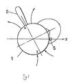
- Fig. 1 shows a principle of an operating device of the present invention.
- a lever 2 is attached to a magnetized spherical body 1 serving as a magnet with penetrating therethrough.
- the spherical body 1 is magnetized in the axial direction of the lever.
- the magnetic force lines generated from the spherical magnet 1 are shown in the figure.
- the component perpendicular to the surface has the highest intensity on both magnetic poles of the spherical body.
- the intensity of the magnetic field decreases as getting close to the equator of the spherical body, and becomes zero on the equator. After going over the equator, the intensity inversely increase.
- the operation device is arranged such that both signals in the x-direction and y-direction become zero when the lever 2 attached to the spherical body 1 is located at a vertical or upright position. That is, in this position, a magnetic sensor 5 is disposed on an extension of the equatorial plane of the spherical body 1 and facing the surface of the spherical body 1 to provide a signal in response to the intensity of the magnetic field component perpendicular to the surface of the spherical body. When the lever is inclined, the magnetic sensor 5 gets close to either one of the magnetic poles of the spherical body, and thereby a signal as shown in Fig. 2 is output according to the inclination with respect to the upright position of the lever 2.
- This signal curve has a shape as sort of a sine function.
- the curve When the lever is inclined approximately to a horizontal position, the curve has two peaks in the maximum value zone under the influence of a hole for inserting the lever thereinto. However, the curve is substantially linearly changed over a range of about 60 degrees ( ⁇ 30 degrees) around zero point of the inclination of the lever. While the above description has been given based on the spherical body, the same can be applied to the cylindrical body. The present invention is constructed with focusing on this point.
- a pair of magnetic sensors are disposed with defining an inner angle of 90-degree therebetween with respect to the center of the spherical body 1 so as to pick up both x-direction and y-direction components from a single inclining movement of the lever 2 to output respective control signals.
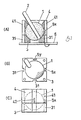
- Fig. 3 shows a case in which the present invention is applied to a joystick for two-dimensional operations.
- the reference numeral 1 indicates a magnet formed by molding a magnetic plastic material in a spherical shape.
- a through-hole 2 is perforated along one of the diametrical directions of the magnet, and a lever 2 is inserted into the through-hole.
- the magnet may be magnetized either before or after making the through-hole.
- a hole to be provided in the magnet does not have to be a through-hole because such a hole is necessary only for inserting the lever thereinto.
- the reference numeral 3 indicates a spherical bearing seat formed by molding a plastic material capable of providing a smooth or slippery surface, such as fluorocarbon resin.
- the bearing seat 3 includes a spherical concave having a depth slightly shorter than the radius of the spherical body, and the bearing seat 3 rotatably supports the spherical magnet 1.
- the reference numeral 4 indicates a bearing cap formed by molding fluorocarbon resin as in the bearing seat 3.
- the bearing cap 4 includes a spherical concave having a depth slightly longer than the radius of the spherical body or slightly getting across the equator of the spherical body 1.
- the spherical concave of the bearing cap 4 forms a spherical space corresponding to the spherical body 1 in combination with the spherical concave of the spherical bearing seat 3.
- the bearing cap 4 has a square-shaped top face and four sides each formed with a groove 41 at the middle region thereof. Since the bearing cap 4 is made of a plastic material, the elasticity of the plastic material allows a core of a molding die to be pulled out after molding. In assembling process, the bearing cap 4 can also be pushed down toward the spherical body 1 placed on the spherical bearing seat 3. Further, the grooves 41 having a thin bottom thickness and including an expanding slot 42 facilitates the above assembling operation.
- a pair of hall elements as magnetic sensors 5x, 5y are adhesively fixed at the bottoms of two grooves adjacent to each other among the four grooves in the bearing cap, respectively.
- This structure allows each of the hall elements to be disposed in non-contact manner with keeping a certain distance to the surface of the spherical body 1 and close to each other.
- the spherical bearing seat 3 has four rectangular sides.
- a groove 31 is provided in the sides at a position corresponding to the hall elements 5x, 5y to serve as a passage for drawing out each lead wire of the hall elements.
- the spherical bearing seat 3 and bearing cap 4 may be jointed at each corner thereof with a screw. Alternatively, they may be joined with an adhesive or by engaging suitable engagement concave and convex portions. In the above manner, a base component of the joystick is completed. Then, the spherical bearing seat 3 is mounted on a suitable position in a circuit board 6, and each lead wire of the hall elements is connected to a printed circuit board.
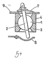
- Fig. 4 shows an example in which a click function is incorporated into a joystick of the present invention. Elements or components corresponding to those of Fig. 3 will be defined by the same reference numerals.
- a lever 2 slidably penetrates a spherical body 1.
- the lever 2 is usually biased upward by a spring 7 interposed between a top plate 9 and a pin knocked in the upper portion of the lever 2.
- the lever 2 is pushed down.
- the lower end of the lever 2 is protruded downward from the spherical body 1, and is brought into contact with a conductive plate 8 disposed under the spherical body 1.
- the conductive plate 8 is formed to have a concave surface, and is conductively connected to one terminal of a circuit.
- the lever 2 is conducted with the top plate 9 through the spring 7, and thus the circuit is closed when the lower end of the lever 2 is brought into contact with the conductive plate 8.
- a magnet may be attached to the lower end of the lever 2 to close a proximity switch by pushing down the lever 2 without closing the circuit directly through the lever 2.
- a joystick can be constructed as a three-dimensional operating device by detecting the vertical movement of the lever 2 and outputting the pushing-down force of the lever 2 as an analog signal.
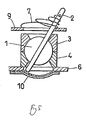
- Such an example is shown in Fig. 5.
- a pressure-sensitive conductive rubber plate 10 is disposed under the lever. This rubber plate is connected in series with a resistor. The voltage at the junction between the resistor and the rubber plate 10 is changed in response to the magnitude of a pressure caused by pressing down the lever 2. This voltage is used as a third z-direction operation signal with respect to x-direction and y-direction operation signals.
- Fig. 6 shows a modification of the example of Fig. 3.
- the spherical bearing seat 3 and the bearing cap 4 include a pair of steps 11 to be engaged with each other just on the equatorial plane of the spherical body 1, respectively.
- a recessed portion 12 is formed in each inner surface of the spherical bearing seat 3 and the bearing cap 4 to allow a thin ring 13 made of fluorocarbon resin to be fitted thereinto.
- the grooves 31, 41 are formed in the outer surfaces of the spherical bearing seat and the bearing cap. The hall elements 5x, 5y are put in these groove portions, and the hall elements are brought pressingly into contact with the ring 13.
- the thickness of the ring 13 acts as a spacer for keeping the hall elements and the surface of the spherical body 1 in a close relationship with leaving a constant distance therebetween.
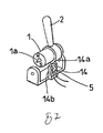
- Fig. 7 shows an example in which the present invention is applied to a one-dimensional lever type operating device.
- the reference number 1 indicates a cylindrical magnetic body having a shaft 1a formed therein by an insert molding process.
- the cylindrical body 1 is magnetized in one of the diametrical directions thereof to form a magnet.
- the shaft 1a may be formed of either a magnetic material or a nonmagnetic material as long as the symmetric property of the magnetic field on the surface of the magnet is demolished by the shaft.
- a lever 2 includes a ring portion, and the magnet 1 is fitted into and fixed by the ring portion.
- the axial direction of the lever 2 is matched with the magnetizing direction of the magnet 1.
- the reference number 14 indicates a bracket for supporting the magnet 1 formed by molding a plastic material.
- the shaft 1a protruded from both ends of the magnet 1 is supported by pivot holes 14a which are formed in standing potions of both sides of the bracket, respectively.
- the standing portions of the bracket may be slightly expanded elastically to allow the magnet 1 to be pushed in the pivot holes.
- the bracket includes another standing portion 14b to which a hall element 5 is fixedly attached.
- the standing portion 14b is inclined slightly inward in its free state.
- this standing portion 14b can also acts as a spacer for keeping the distance between the hale element 5 and the surface of the magnet constant.
- the shaft 1a may be formed integrally with the magnet 1 by molding with the same material as that of the magnet 1.
- the magnet is described as a spherical or cylindrical body.
- both magnetic pole regions are substantially flattened because the lever penetrates the spherical magnet.
- the influence of these flattened regions appears at the lever inclinations of zero degree and 180 degrees.
- the present invention is based on the principle that the angle (latitude) dependence of magnetic field intensity is essentially point-symmetric with respect to 90 degrees, and the magnetic field intensity is linearly changed over a wide angle range on both sides of 90 degrees.
- both the magnetic pole regions may be widely flattened.
- Fig. 9 shows the relationship between the magnetic field intensity and the angle in case that both the magnetic pole regions of a spherical magnet are flattened and the distance between both the magnetic poles is set in 3/5 of the diameter of the spherical magnet. It is proved that a sufficient linearity can be maintained over a range of about 30 degrees on both sides of the point of 90 degrees while the width between two peaks in both the magnetic pole regions is increased.
- spherical or “cylindrical” herein includes the case in which both the magnetic pole regions of a magnet are symmetrically flattened.
- the lever has been penetrated through the spherical body or cylindrical body in the magnetizing direction thereof in the above description, it is apparent that the lever may be attached with an appropriate inclination according to the need of device design.
- the lever may be largely inclined with respect to both the magnetic poles of the magnet.
- a spherical or cylindrical magnetic body magnetized in one of the diametrical directions thereof is rotatably supported and a magnetic sensor is disposed close to the surface of the magnet to detect the intensity of the magnetic field component perpendicular to the surface of the magnet.
- the structure of the device is very simple with the reduced number of parts and the magnet can be readily produced. This facilitates downsizing of the device, and allows any electrical component involved with sliding movement to be eliminated so as to provide desirable durability. Further, smooth and linear change in magnetic intensity can be achieved to provide a high degree of accuracy. Accordingly, the present invention is applicable in various fields, such as an operating device for portable computers, an operating device for various machines, for example used in operating a crane, or remote-controlling a robot, or the like.
Landscapes
- Physics & Mathematics (AREA)
- General Physics & Mathematics (AREA)
- Engineering & Computer Science (AREA)
- Automation & Control Theory (AREA)
- Switches With Compound Operations (AREA)
- Mechanical Control Devices (AREA)
- Position Input By Displaying (AREA)
Applications Claiming Priority (3)
| Application Number | Priority Date | Filing Date | Title |
|---|---|---|---|
| JP2000025141 | 2000-02-02 | ||
| JP2000025141 | 2000-02-02 | ||
| PCT/JP2001/000783 WO2001057639A1 (fr) | 2000-02-02 | 2001-02-02 | Dispositif de commande de type levier |
Publications (1)
| Publication Number | Publication Date |
|---|---|
| EP1300751A1 true EP1300751A1 (fr) | 2003-04-09 |
Family
ID=18551040
Family Applications (1)
| Application Number | Title | Priority Date | Filing Date |
|---|---|---|---|
| EP01904321A Withdrawn EP1300751A1 (fr) | 2000-02-02 | 2001-02-02 | Dispositif de commande de type levier |
Country Status (3)
| Country | Link |
|---|---|
| US (1) | US20020149565A1 (fr) |
| EP (1) | EP1300751A1 (fr) |
| WO (1) | WO2001057639A1 (fr) |
Families Citing this family (17)
| Publication number | Priority date | Publication date | Assignee | Title |
|---|---|---|---|---|
| DE10134259A1 (de) | 2001-07-18 | 2003-02-06 | Zf Lemfoerder Metallwaren Ag | Kugelgelenk mit integriertem Winkelsensor |
| DE10140683A1 (de) * | 2001-08-24 | 2003-03-06 | Zf Lemfoerder Metallwaren Ag | Kugelgelenk |
| DE10161671A1 (de) | 2001-12-14 | 2003-06-26 | Zf Lemfoerder Metallwaren Ag | Kugelgelenk für ein Kraftfahrzeug |
| US7096796B2 (en) | 2003-02-28 | 2006-08-29 | Honeywell International Inc. | Brake handle with integral position sensing switch |
| US20040168539A1 (en) * | 2003-02-28 | 2004-09-02 | Honeywell International Inc. | Brake handle with integral position sensing |
| DE10338833B4 (de) * | 2003-08-21 | 2005-12-22 | Zf Friedrichshafen Ag | Kugelgelenk mit Schwenkwinkelsensor |
| US8482523B2 (en) * | 2005-08-17 | 2013-07-09 | Sauer-Danfoss Inc. | Magnetic control device |
| DE102006059822A1 (de) * | 2006-12-11 | 2008-06-12 | Integrated Electronic Systems !Sys Consulting Gmbh | Elektrische Steuereinrichtung |
| DE102008013280B4 (de) * | 2007-03-16 | 2019-01-31 | Danfoss Power Solutions Aps | Joystick mit einer Sensoreinrichtung |
| US8174255B2 (en) * | 2007-06-21 | 2012-05-08 | Mason Electric Co. | Hall effect system |
| ITPD20070271A1 (it) * | 2007-08-03 | 2009-02-04 | Paolo Andreotti | Dispositivo elettronico di miscelazione e di regolazione della portata d' acqua |
| WO2009090137A1 (fr) * | 2008-01-14 | 2009-07-23 | Rema Lipprandt Gmbh & Co. Kg | Joystick |
| ES2395599T3 (es) * | 2009-02-17 | 2013-02-13 | Kwc Ag | Grifería sanitaria con control de mando |
| EP2218839B1 (fr) * | 2009-02-17 | 2013-06-12 | Kwc Ag | Armature sanitaire dotée d'une articulation |
| US9870021B2 (en) * | 2009-04-15 | 2018-01-16 | SeeScan, Inc. | Magnetic manual user interface devices |
| RU171081U1 (ru) * | 2017-03-07 | 2017-05-19 | федеральное государственное автономное образовательное учреждение высшего образования "Санкт-Петербургский политехнический университет Петра Великого" (ФГАОУ ВО "СПбПУ") | Магнитный джойстик |
| WO2020218702A1 (fr) * | 2019-04-20 | 2020-10-29 | 주식회사 와이드벤티지 | Dispositif d'entrée servant à délivrer une entrée utilisateur |
Family Cites Families (9)
| Publication number | Priority date | Publication date | Assignee | Title |
|---|---|---|---|---|
| NL8002727A (nl) * | 1980-05-12 | 1981-12-16 | Applied Electronics Bv | Kontaktloze, elektrische besturingshandel. |
| JPS5865505U (ja) * | 1981-10-27 | 1983-05-04 | 日本電気ホームエレクトロニクス株式会社 | ジヨイステイツク |
| JPS58150234U (ja) * | 1982-03-31 | 1983-10-08 | 日本電気ホームエレクトロニクス株式会社 | 非接触型ジヨイステイツク |
| US4489303A (en) * | 1983-06-03 | 1984-12-18 | Advanced Control Systems | Contactless switch and joystick controller using Hall elements |
| US4825157A (en) * | 1988-05-16 | 1989-04-25 | Mikan Peter J | Hall-effect controller |
| US5286024A (en) * | 1991-03-20 | 1994-02-15 | Atari Games Corporation | System for sensing the position of a joystick |
| US5421694A (en) * | 1993-05-20 | 1995-06-06 | Caterpillar Inc. | Non-contacting joystick |
| US5969520A (en) * | 1997-10-16 | 1999-10-19 | Sauer Inc. | Magnetic ball joystick |
| JP2887285B1 (ja) * | 1998-03-19 | 1999-04-26 | 川崎重工業株式会社 | 球ジョイント回転検出装置 |
-
2001
- 2001-02-02 EP EP01904321A patent/EP1300751A1/fr not_active Withdrawn
- 2001-02-02 US US10/070,418 patent/US20020149565A1/en not_active Abandoned
- 2001-02-02 WO PCT/JP2001/000783 patent/WO2001057639A1/fr not_active Ceased
Non-Patent Citations (1)
| Title |
|---|
| See references of WO0157639A1 * |
Also Published As
| Publication number | Publication date |
|---|---|
| US20020149565A1 (en) | 2002-10-17 |
| WO2001057639A1 (fr) | 2001-08-09 |
Similar Documents
| Publication | Publication Date | Title |
|---|---|---|
| EP1300751A1 (fr) | Dispositif de commande de type levier | |
| US6606085B1 (en) | Coordinate input device | |
| JP3455706B2 (ja) | テーパー付きの二極の磁石を用いる非接触式のポジションセンサ | |
| EP1332279B1 (fr) | Capteur de position de pedale faisant appel a des aimants effiles bipolaires | |
| US8122783B2 (en) | Joystick and method of manufacturing the same | |
| US20060208840A1 (en) | Trackball device | |
| CN101315569B (zh) | 多方向输入装置 | |
| US6611139B1 (en) | Three dimensional positioning device | |
| EP1380927A1 (fr) | Dispositif pointeur | |
| US11650675B2 (en) | Input device with movable handle on a capacitive detection surface and capacitive coupling devices | |
| JP2009016114A (ja) | 複合操作型入力装置 | |
| JP2003151410A (ja) | タッチセンサ部構造 | |
| EP4625094A1 (fr) | Dispositif de culbuteur doté d'une fonction de retour automatique au centre | |
| JPH11232968A (ja) | スティックコントローラ | |
| US20030112158A1 (en) | Miniature magnetic device package | |
| AU2019427466B2 (en) | Inductive joystick | |
| JP2002542473A (ja) | 回転角を無接触方式で検出するための測定装置 | |
| JP4021037B2 (ja) | スティックコントローラ | |
| JP7835615B2 (ja) | 多方向入力装置 | |
| JP2002140160A (ja) | トラックボール装置 | |
| JPH11224570A (ja) | スティックコントローラ | |
| JP2001290594A (ja) | レバー式操作装置 | |
| US5386089A (en) | Track ball coordinate data inputting device | |
| JPH08152961A (ja) | ポインティングデバイス | |
| JP2001264052A (ja) | 感傾装置 |
Legal Events
| Date | Code | Title | Description |
|---|---|---|---|
| PUAI | Public reference made under article 153(3) epc to a published international application that has entered the european phase |
Free format text: ORIGINAL CODE: 0009012 |
|
| PUAB | Information related to the publication of an a document modified or deleted |
Free format text: ORIGINAL CODE: 0009199EPPU |
|
| PUAF | Information related to the publication of a search report (a3 document) modified or deleted |
Free format text: ORIGINAL CODE: 0009199SEPU |
|
| PUAI | Public reference made under article 153(3) epc to a published international application that has entered the european phase |
Free format text: ORIGINAL CODE: 0009012 |
|
| 17P | Request for examination filed |
Effective date: 20020212 |
|
| AK | Designated contracting states |
Kind code of ref document: A1 Designated state(s): AT BE CH CY DE DK ES FI FR GB GR IE IT LI LU MC NL PT SE TR Designated state(s): AT BE CH CY DE DK ES FI FR GB GR IE IT LI LU MC NL PT SE TR |
|
| AX | Request for extension of the european patent |
Extension state: AL LT LV MK RO SI |
|
| RBV | Designated contracting states (corrected) |
Designated state(s): DE FR GB |
|
| STAA | Information on the status of an ep patent application or granted ep patent |
Free format text: STATUS: THE APPLICATION IS DEEMED TO BE WITHDRAWN |
|
| 18D | Application deemed to be withdrawn |
Effective date: 20040901 |