EP1300931A2 - Bürstenloser Gleichstrommotor - Google Patents
Bürstenloser Gleichstrommotor Download PDFInfo
- Publication number
- EP1300931A2 EP1300931A2 EP02256494A EP02256494A EP1300931A2 EP 1300931 A2 EP1300931 A2 EP 1300931A2 EP 02256494 A EP02256494 A EP 02256494A EP 02256494 A EP02256494 A EP 02256494A EP 1300931 A2 EP1300931 A2 EP 1300931A2
- Authority
- EP
- European Patent Office
- Prior art keywords
- motor
- winding
- brushless
- stator
- yoke
- Prior art date
- Legal status (The legal status is an assumption and is not a legal conclusion. Google has not performed a legal analysis and makes no representation as to the accuracy of the status listed.)
- Withdrawn
Links
Images


Classifications
-
- H—ELECTRICITY
- H02—GENERATION; CONVERSION OR DISTRIBUTION OF ELECTRIC POWER
- H02K—DYNAMO-ELECTRIC MACHINES
- H02K29/00—Motors or generators having non-mechanical commutating devices, e.g. discharge tubes or semiconductor devices
- H02K29/06—Motors or generators having non-mechanical commutating devices, e.g. discharge tubes or semiconductor devices with position sensing devices
- H02K29/08—Motors or generators having non-mechanical commutating devices, e.g. discharge tubes or semiconductor devices with position sensing devices using magnetic effect devices, e.g. Hall-plates, magneto-resistors
-
- H—ELECTRICITY
- H02—GENERATION; CONVERSION OR DISTRIBUTION OF ELECTRIC POWER
- H02K—DYNAMO-ELECTRIC MACHINES
- H02K11/00—Structural association of dynamo-electric machines with electric components or with devices for shielding, monitoring or protection
- H02K11/30—Structural association with control circuits or drive circuits
- H02K11/33—Drive circuits, e.g. power electronics
-
- H—ELECTRICITY
- H02—GENERATION; CONVERSION OR DISTRIBUTION OF ELECTRIC POWER
- H02K—DYNAMO-ELECTRIC MACHINES
- H02K21/00—Synchronous motors having permanent magnets; Synchronous generators having permanent magnets
- H02K21/12—Synchronous motors having permanent magnets; Synchronous generators having permanent magnets with stationary armatures and rotating magnets
- H02K21/22—Synchronous motors having permanent magnets; Synchronous generators having permanent magnets with stationary armatures and rotating magnets with magnets rotating around the armatures, e.g. flywheel magnetos
- H02K21/227—Synchronous motors having permanent magnets; Synchronous generators having permanent magnets with stationary armatures and rotating magnets with magnets rotating around the armatures, e.g. flywheel magnetos having an annular armature coil
-
- Y—GENERAL TAGGING OF NEW TECHNOLOGICAL DEVELOPMENTS; GENERAL TAGGING OF CROSS-SECTIONAL TECHNOLOGIES SPANNING OVER SEVERAL SECTIONS OF THE IPC; TECHNICAL SUBJECTS COVERED BY FORMER USPC CROSS-REFERENCE ART COLLECTIONS [XRACs] AND DIGESTS
- Y10—TECHNICAL SUBJECTS COVERED BY FORMER USPC
- Y10S—TECHNICAL SUBJECTS COVERED BY FORMER USPC CROSS-REFERENCE ART COLLECTIONS [XRACs] AND DIGESTS
- Y10S310/00—Electrical generator or motor structure
- Y10S310/06—Printed-circuit motors and components
Definitions
- This invention relates to a brushless DC motor having a magnet magnetized so as to have a plurality of magnet poles in the circumferential direction thereof for use in a small fun ⁇ blower and, more particularly, relates to a brushless DC motor comprising two stator yokes, each having main magnetic pole and magnetic pole pieces, a center yoke passing through the center portions of the two stator yokes for connecting magnetically the two stator yokes, and an annular winding arranged between the two stator yokes.
- Japanese Utility Model Laid-Open No. 153486/86, Japanese Patent Laid-Open No. 63065/83, Japanese Patent Laid-Open No. 214759/86, Japanese Patent Laid-Open No. 23754/89, and Japanese Patent Laid-Open No. 303750/94 propose many kinds of the brushless DC motor.
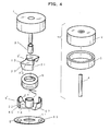
- FIG. 8 is an exploded view of the conventional brushless DC motor disclosed in the Japanese Patent Laid-Open No. 23754/89.
- FIG. 9 shows a relation between the magnet and the stator yokes.
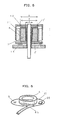
- FIG. 10 is a sectional view of the conventional brushless DC motor.
- the brushless DC motor of four poles shown in FIG. 8 has a rotor 1 consisting of a cylindrical rotor yoke 2 of the magnetic material, a magnet 3 magnetized so as to have a plurality of magnet poles in the circumferential direction thereof, and a motor shaft 4.
- Reference numeral 5 denotes a first stator yoke having two main magnetic poles 13 and magnetic pole pieces 21.
- Reference numeral 23 denotes a bobbin, 24 denotes an annular winding wound around the bobbin 23.
- Reference numeral 25 denotes terminals mounted on the bobbin 23, to each of the terminals 25 each of lead wires of the winding 24 being tied up and soldered, 6 denotes a second stator yoke having two main magnetic poles 14 and magnetic pole pieces 22.
- Reference numeral 7 denotes cylindrical center yokes formed on center portions of the first and second stator yokes 5 and 6, inserted telescopically each other so as to connect magnetically the first and second stator yokes 5 and 6 each other
- 17 denotes a slit formed axially on each of the center yokes 7
- 9 denotes an electromagnetic conversion element, such as a Hall element for detecting the magnet pole of the magnet 3
- 11 denotes a printed wiring board for connecting electrically the Hall element 9 and the terminals 25 to a driving circuit.
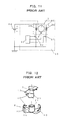
- FIG. 11 shows a driving circuit for two-phase half-wave electric currents energizing alternately two windings 24a and 24b having a phase difference of 180° in electrical angle.
- reference numeral 60 denotes a motor portion
- 61 and 62 denote transistors each driven by a signal from a motor driving IC 63
- 64 denotes a DC power source
- 65 denotes electric parts or IC parts installed on the printing wiring board 11.
- the motor shown in FIG. 9 however, has a dead point at which the motor cannot be driven in principle due to the specific arrangement of the magnet and the magnetic pole pieces. In order to avoid such dead point and to reduce a torque ripple during the rotation of the motor, a relative position of the magnet and the magnetic pole pieces is considered.
- a spread angle a of the magnetic pole piece is 1/5 to 4/5 of that of one magnet pole of the magnet 3, and to set a spread angle b formed between the center lines of the magnetic pole pieces 21 and 22 of the first and second stator yokes 5 and 6 to ⁇ /4 to 3 ⁇ /4 in electrical angle.
- a high speed brushless DC motor it is preferable for a high speed brushless DC motor to provide a slit 17 in the axial direction in each of the center yokes 7, in order to reduce the eddy current and the eddy current loss produced by the magnetic flux in the axial direction.
- the winding 24 is wound around the bobbin 23, the lead wires of the winding 24 are tied up and soldered to the terminals 25 mounted on the printed wiring board 11, as shown in FIG. 8 of the present application.
- the cost for the parts, such as the bobbin 23 and the terminals 25 is increased.
- the treatment of the lead wires of the winding and the soldering thereof are complicated and the cost thereof is increased.
- the magnetic flux from the magnet cannot be used effectively, because the space angles of the first and second stator yokes are different from each other and thus the spread angle a of the magnetic pole piece becomes small with respect to that of the one magnet pole of the magnet.
- a magnetic flux from the N pole of the magnet 3 is returned to the S pole of the magnet 3 through the first stator yoke 5, the center yokes 7 and the second stator yoke 6.
- the magnetic flux from the N pole to the S pole of the magnet 3 is limited and entire magnetic flux cannot be returned to the S pole of the magnet, because a portion of the magnetic pole piece of the second stator yoke 6 is positioned at the boundary of the N and S poles of the magnet.
- the effective interlinkage magnetic flux and thus the motor efficiency are reduced, because the magnetic flux passing through the center yokes 7 is interlinkaged with the annular winding.
- FIG. 7 is a graph showing relations between the interlinkage magnetic flux of the motor winding and the counter electromotive force with respect to the motor revolution, in case that the materials and figure of the center yoke are varied.
- a curve 1 ⁇ shows the counter electromotive force in case that an electromagnetic soft iron is used
- 4 ⁇ shows the interlinkage magnetic flux.
- the frequency of the alternating magnetic flux passing through the center yoke becomes high and the interlinkage magnetic flux is suppressed by the eddy current according to the increase of the rotation, so that the counter electromotive force is saturated.
- FIG. 7 is a graph showing relations between the interlinkage magnetic flux of the motor winding and the counter electromotive force with respect to the motor revolution, in case that the materials and figure of the center yoke are varied.
- a curve 1 ⁇ shows the counter electromotive force in case that an electromagnetic soft iron is used
- 4 ⁇ shows the interlinkage magnetic flux.
- the frequency of the alternating magnetic flux passing through the center yoke
- a curve 2 ⁇ shows the counter electromotive force and 5 ⁇ shows the interlinkage magnetic flux in case that one slit 17 is formed axially in each of the center yokes 7 as shown in FIG. 8.
- the spread angle c of the magnetic pole piece 22 of the second stator yoke 6 is smaller than the spread angle a of the magnetic pole piece 21 of the first stator yoke 5, as shown in FIG. 9 of the present application, so that the width of the magnetic pole piece 22 becomes small, the effective interlinkage magnetic flux of the motor is reduced, and the motor efficiency is also reduced.
- the area of the magnetic pole piece is reduced and the effective interlinkage magnetic flux is also reduced, because the projecting portions 20 is provided on the magnetic pole pieces 21 and 22, as shown in FIG. 12 of the present application.
- the magnetic flux passing through the electromagnetic steel plate of each of stator yokes is saturated, because the thickness of the electromagnetic steel plate is limited in most cases.
- the magnetic flux from the magnet 3 is passed through the tip end of the magnetic pole piece to the main magnet pole, and the density of the magnetic flux is large, so that there is a possibility of saturation of the magnetic flux if the passage of the magnetic flux is narrowed.
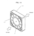
- FIG. 13 is a perspective view of a small fan motor.
- a reference numeral 50 denotes a fan case and 51 denotes blades provided on the rotor yoke 2.
- the outer diameter of the rotor yoke 2 of the brushless DC motor positioned at the center of the fan is reduced to a value lower than 55% of the outer diameter of the blade 51, in order to increase the quantity of the suction wind.
- the thickness of the bobbin 23 used for winding of the winding 24 and the insulation thereof is larger than about 0.5mm. Accordingly, the space of the winding 24 is reduced by the thickness of the bobbin 23.
- the space factor of the winding becomes lower than 80%, and the output and the efficiency of the motor are reduced.
- the diameter of the motor cannot be reduced, because the space for the bobbin 23 is necessary. As a result, the blade of the fan ⁇ blower becomes small and the efficiency is lowered. Further, the noise due to the motor oscillation is increased if the motor input is increased in order to increase the quantity of wind of the fan ⁇ blower.
- the winding 24 itself is heated by the electric current passing through the winding 24 when the motor is driven.
- the bobbin 23 is formed of the resin and thus the heat conductivity is small, so that the heat radiation from the stator yokes 5 and 6 is small, the temperature of the motor is increased, and the life time of the bearing of the fan ⁇ blower is shortened.
- An object of the present invention is to solve the above technical problems.
- Another object of the present invention is to provide a small motor of a high efficiency suitable for use in the small fan ⁇ blower, wherein the number of the parts is reduced, the cost is reduced remarkably by improving the treatment of the lead wires of the winding, the reduction of the effective interlinkage magnetic flux of the motor is prevented, and the oscillation of the magnetic pole piece is prevented.
- a further object of the present invention is to provide a brushless DC motor, wherein a winding assembly is composed of an annular winding, an electromagnetic conversion element, and a driving circuit mounted on a printed wiring board; main magnetic poles of a first stator yoke is deviated by about 180° in electrical angle from main magnetic poles of a second stator yoke; both end surfaces of the winding assembly are held by the main magnetic poles of the first and second stator yokes; an outer peripheral surface of the annular winding is covered with magnetic pole pieces of the first and second stator yokes; and a center yoke is positioned at the center of the winding assembly.
- the annular winding is an air-core winding and formed of two normally tight wound self welding wires, each wire having an adhesive film around an insulating coating thereof, the winding being energized by two-phase half-wave electric currents having a phase difference of 180° in electrical angle.
- the printed wiring board is flexible.
- At least one of the first and second stator yokes is movable in the axial direction thereof so as to meet with a change of the length of the annular winding.
- At least one of the magnetic pole pieces of the first and second stator yokes has a cutout portion so as to reduce gradually an area of the magnetic pole piece toward the tip end thereof.
- the center yoke is made of a soft magnetic stainless steel comprising 10-15 wt % of chrome and 85-90 wt % of iron.
- Still further object of the present invention is to provide a brushlees DC motor, wherein two sets of stator yokes are coated with thin insulating films, and an annular winding formed of self welding wires is inserted into a space formed between the center yoke and the magnetic pole pieces without forming any gap substantially therebetween, so that the space factor of the winding becomes near 100 %.
- stator yokes and the annular winding are impregnated with a liquid insulating material and connected each other so as to increase the heat radiation of the annular winding.
- a thin insulating sheet instead of the thin insulating coating for the first and second stator yokes is used.
- Yet further object of the present invention is to provide a brushless DC motor for use in a driving source of a small fan ⁇ blower in order to increase the efficiency remarkably and reduce the noise.
- FIG. 1 is an exploded view of a brushless DC motor of a first embodiment according to the present invention.
- FIG. 2 is a horizontally sectional view of the brushless DC motor of the first embodiment according to the present invention showing a relation between a magnet and stator yokes thereof.
- FIG. 3 is a vertically sectional view of the brushless DC motor of the first embodiment according to the present invention.
- FIG. 4 is an exploded view of a brushless DC motor of a second embodiment according to the present invention.
- FIG. 5 is a vertically sectional view of the brushless DC motor of the second embodiment according to the present invention.
- FIG. 6 is a perspective view of a winding assembly of the brushless DC motor of the first embodiment according to the present invention.
- FIG. 7 is a graph showing a specific properties of the brushless DC motor according to the present invention.
- FIG. 8 is an exploded view of the conventional brushless CD motor.
- FIG. 9 is a horizontally sectional view of the conventional brushless DC motor showing a relation between the magnet and the stator yokes thereof.
- FIG. 10 is a vertically sectional view of the conventional brushless DC motor.
- FIG. 11 shows a driving circuit of the conventional brushless DC motor.
- FIG. 12 is an exploded view of the stator yokes of the conventional brushless DC motor.
- FIG. 13 is a perspective view of a small fan using the motor according to the present invention.
- a brushless DC motor of a first embodiment according to the present invention will be explained. Parts of the motor which are similar to corresponding parts of the conventional motor shown in FIG. 8 to FIG. 12 have been given corresponding reference numerals and need not be further redescribed. As shown in FIG. 1, electric parts 65 and a Hall element 9 used as an electromagnetic conversion element are mounted on a printed wiring board 11, an air-core annular winding 8 having no bobbin is fixed on the printed wiring board 11, and lead wires of the winding 8 are connected directly by soldering on the printed wiring board 11 to form a winding assembly 12.
- a first stator yoke 5 comprising two planar main magnetic poles 13 extending radially outwardly from the center thereof, and two magnetic pole pieces 21 extending axially from the tip ends of the main magnetic poles 13 is provided.
- a second stator yoke 6 comprising two planar main magnetic poles 14 extending radially outwardly from the center thereof, and two magnetic pole pieces 22 extending axially from tip ends of the main magnet poles 14 is provided.
- a center yoke 7 is provided at the center of each of the first and second stator yokes 5 and 6 and inserted into the center hole of the winding assembly 12.
- the first stator yoke 5 is arranged so as to deviate by 180° in electrical angle from the second stator yoke 6.
- the winding assembly 12 is held by the first and second stator yokes 5 and 6.
- a rotor 1 formed of a rotor yoke 2, a magnet 3 magnetized so as to have a plurality of magnet poles in the circumferential direction thereof, and a shaft 4 is combined with the winding assembly 12, so as to form a brushless DC motor.
- the wiring of the electric circuit is completed before the motor is assembled, so that the test of the circuit operation can be carried out before the motor is assembled and thus the operation efficiency is increased. Further, a bobbin 23 for the winding and a terminal can be omitted, so that the cost of parts can be reduced.
- the air-core bifilar annular winding 8 is formed by forwarding two self welding wires in parallel at the same time. According to this embodiment, the space factor of the winding is increased because the winding is formed by the substantial normal winding, and it is possible to increase the motor efficiency.
- FIG. 6 shows the winding assembly 12 of the present invention.
- a flexible printed wiring board 11 small in thickness is used in order to increase a space for the winding 24, so that the space factor and the motor efficiency are increased.
- a portion 45 is projected from the outer peripheral surface of the board 11 for holding lead wires to be connected to the power source or the like outside of the motor.
- a cutout portion 27 is formed at one side edge of each of the magnetic pole pieces 21 and 22 so as to reduce gradually the surface area of each of the magnetic pole pieces 21 and 22 toward a tip end thereof.
- the stator yokes 5 and 6 are deviated by 180° in electrical angle from each other.
- a spread angle a of each of the magnetic pole pieces 21 and 22 is 7/10 to 9/10 of that of one magnet pole of the magnet 3.
- the current of the magnetic flux is not limited and it is possible to increase the effective interlinkage magnetic flux of the motor, because the spread angle a of the magnetic pole piece can be increased and the each of the magnetic pole pieces can be arranged in the same angular position with the magnet 3, on the contrary to the conventional motor.
- the motor wherein the magnet poles of the magnet 3 and the stator yokes 5 and 6 are positioned as shown in FIG. 2 has a dead point, at which the motor cannot be started.
- the motor of the present invention has no such dead point, because the cogging torque generating position is shifted by the presence of the cutout portion 27.
- cutout portion 27 is not formed on a connecting portion 40 of the main magnetic pole and the magnetic pole piece, so that a force against the radial direction of the stator yoke is not reduced, and the oscillation of the stator yoke is not increased.
- center portions of the first and second stator yokes 5 and 6 are drawn to form tubes, so that the tubes are fitted telescopically each other to form the center yokes 7 for connecting magnetically the first and second stator yokes 5 and 6.
- a ring spacer 16 is inserted between the first and second stator yokes 5 and 6.
- the brushless DC motor of the present invention shown in FIG. 3 will be compared with the conventional brushless DC motor shown in FIG. 10 hereunder.
- the axial lengths of the annular winding 8 and the magnet 3 can be extended by the inserted ring spacer 16, so that the ampereturn and thus the motor power can be increased.
- FIG. 7 shows a line 3 ⁇ of a counter electromotive force and a line 6 ⁇ of an interlinkage magnetic flux in case that the center yoke 7 is made of a soft magnetic stainless steel plate comprising 10-15 wt % of chrome and 85-90 wt% of iron.
- the electric resistivity of the soft magnetic stainless steel plate is 6300 ( ⁇ m ), whereas the electric resistivity of the standard electromagnetic soft iron is 1400 ( ⁇ m). Accordingly, as shown in FIG. 7, the properties of the counter electromotive force and the interlinkage magnetic flux are enhanced in the entire range of rotation from the low speed to the high speed.
- FIG. 4 shows a second embodiment of the present invention.
- a first stator yoke 5' comprising two planar main magnetic poles 13 extending radially outwardly from the center thereof, and two magnetic pole pieces 21 extending axially from the tip ends of the main magnetic poles 13
- a second stator yoke 6' comprising two planar main magnetic poles 14 extending radially outwardly from the center thereof, and two magnetic pole pieces 22 extending axially from tip ends of the main magnet poles 14 is provided.
- a center yoke 7 is provided at the center of each of the first and second stator yokes 5' and 6' and inserted into the center hole of an annular air-core winding 8.
- the first stator yoke 5' is arranged so as to deviate by 180° in electrical angle from the second stator yoke 6'.
- the first and second stator yokes 5' and 6' are covered with thin insulating films.
- the winding 8 is held by the first and second stator yokes 5' and 6'.
- a rotor 1 formed of a rotor yoke 2, a magnet 3 magnetized so as to have a plurality of magnet poles in the circumferential direction thereof, and a shaft 4 is combined with the winding 8, so as to form a brushless DC motor.
- stator yoke is formed by laminating stator yoke elements
- annular winding the path of the magnetic flux becomes long, so that the iron loss becomes large.
- the constant of the counter electromotive force relating to the property of the motor is determined by the products of the effective interlinkage magnetic flux of winding, the number of magnet poles and the number of turns of the winding.
- This number of turns of the winding affects on the property of the motor to a large extent, if the effective interlinkage magnetic flux of winding and the number of magnet poles are constant. Accordingly, the number of turns of the winding can be increased by increasing the space factor of the winding, so that it is possible to increase the efficiency of the motor of the annular winding system.
- the space factor of the winding is small in case of the small motor.
- the space factor of the conventional motor having the laminated stator yoke for use in the small fan is 50% to 60%, and the space factor of the conventional motor having the annular winding wound around the bobbin is 70% to 80%, for example.
- the outer diameter A of the magnetic pole pieces of the stator yoke is 18mm
- outer diameter B and the inner diameter C of the annular air-core winding 8 are 17mm and 10.5mm, respectively.
- the inner diameter C of the annular air-core winding 8 having no bobbin is so determined that the center yoke can be fitted into the winding 8 without forming any gap therebetween.
- the stator yoke is coated with a thin insulating paint of about 20 ⁇ m in thickness by the cation electrodeposition. According to such motor, it is possible to increase the space factor to 95% or more.
- the efficiency of the conventional motor having the laminated stator yoke is 25%, and the efficiency of the convention motor having annular winding is 32%. On the contrary thereto, in the present invention, it is possible to increase the efficiency of the motor to 42% under the same outer diameter of the motor.
- the present invention further, it is possible to make smaller in outer diameter of the rotor yoke 2 than that of the conventional motor having the annular winding under the same output property of the motor. Accordingly, in the present invention, the outer diameter of the fan blade 51 can be increased, so that the quantity of suction air of the fan and the efficiency of the fan can be increased. Further, the revolution number of the motor can be reduced under the same quantity of air, because the quantity of suction air is large, so that the noise of the motor can be reduced.
- the winding is formed by using the bobbin of the synthetic resin, so that the heat conductivity of the winding is small in spite of the fact that the winding is self heated by the electric current passing therethrough.
- the winding 24 is contacted intimately substantially with the stator yokes 5 and 6, so that the heat conductivity and the heat radiating effect of the winding 24 are large and it is possible to suppress the elevation of the temperature of the winding.
- the two stator yokes 5' and 6' and the annular winding 8 are impregnated with the varnish and hardened, so that the heat radiating effect is increased.
Landscapes
- Engineering & Computer Science (AREA)
- Power Engineering (AREA)
- Microelectronics & Electronic Packaging (AREA)
- Brushless Motors (AREA)
- Iron Core Of Rotating Electric Machines (AREA)
Applications Claiming Priority (8)
| Application Number | Priority Date | Filing Date | Title |
|---|---|---|---|
| JP2001293264 | 2001-09-26 | ||
| JP2001293264A JP3493188B2 (ja) | 2001-09-26 | 2001-09-26 | ブラシレスdcモータ |
| JP2002158066A JP2004007868A (ja) | 2002-05-30 | 2002-05-30 | ブラシレスdcモータ |
| JP2002158066 | 2002-05-30 | ||
| JP2002158064 | 2002-05-30 | ||
| JP2002158065A JP3613565B2 (ja) | 2002-05-30 | 2002-05-30 | ブラシレスdcモータ |
| JP2002158065 | 2002-05-30 | ||
| JP2002158064A JP2004007866A (ja) | 2002-05-30 | 2002-05-30 | ブラシレスdcモータ |
Publications (2)
| Publication Number | Publication Date |
|---|---|
| EP1300931A2 true EP1300931A2 (de) | 2003-04-09 |
| EP1300931A3 EP1300931A3 (de) | 2003-10-01 |
Family
ID=27482582
Family Applications (1)
| Application Number | Title | Priority Date | Filing Date |
|---|---|---|---|
| EP02256494A Withdrawn EP1300931A3 (de) | 2001-09-26 | 2002-09-19 | Bürstenloser Gleichstrommotor |
Country Status (3)
| Country | Link |
|---|---|
| US (1) | US6710504B2 (de) |
| EP (1) | EP1300931A3 (de) |
| CN (1) | CN1409467A (de) |
Cited By (1)
| Publication number | Priority date | Publication date | Assignee | Title |
|---|---|---|---|---|
| CN1832305B (zh) * | 2005-03-08 | 2010-09-01 | 可斯塔·佩龙尼斯 | 无刷直流风扇马达 |
Families Citing this family (15)
| Publication number | Priority date | Publication date | Assignee | Title |
|---|---|---|---|---|
| GB2401996A (en) * | 2003-04-04 | 2004-11-24 | Sunonwealth Electr Mach Ind Co | Stator construction for a reduced thickness brushless DC motor |
| US6876110B2 (en) * | 2003-08-15 | 2005-04-05 | Comair Rotron, Inc. | Electric motor stator current controller |
| US20060083642A1 (en) * | 2004-10-18 | 2006-04-20 | Cook Martin C | Rotor stability of a rotary pump |
| WO2006089578A1 (de) * | 2005-02-24 | 2006-08-31 | Ebm-Papst St. Georgen Gmbh & Co. Kg | Minilüfter |
| TWI338433B (en) * | 2005-05-13 | 2011-03-01 | Delta Electronics Inc | Fan motor and stator thereof |
| CN100529428C (zh) * | 2005-08-05 | 2009-08-19 | 富准精密工业(深圳)有限公司 | 散热风扇 |
| CN100530909C (zh) * | 2005-09-14 | 2009-08-19 | 台达电子工业股份有限公司 | 无刷直流电机及其定子 |
| CN1945943B (zh) * | 2005-10-09 | 2011-02-09 | 精工电子有限公司 | 步进电机及电子器械 |
| JP4815300B2 (ja) * | 2006-07-31 | 2011-11-16 | 日本電産サンキョー株式会社 | ステッピングモータのステータコアの製造方法並びにそのステッピングモータ |
| JP5558182B2 (ja) * | 2009-05-27 | 2014-07-23 | 山洋電気株式会社 | 電気装置の放熱構造 |
| CN101666086B (zh) * | 2009-08-11 | 2011-08-03 | 上海建工(集团)总公司 | 预制构件水泥土钻孔灌注桩及其施工方法 |
| EP2514081A2 (de) * | 2009-12-14 | 2012-10-24 | Steorn Limited | Elektrischer motor ohne elektromotorische gegenkraft |
| US9638432B2 (en) | 2010-08-31 | 2017-05-02 | Broan-Nutone Llc | Ventilation unit calibration apparatus, system and method |
| CN103269143A (zh) * | 2013-05-06 | 2013-08-28 | 德清县金宇达电气有限公司 | 一种两相无刷直流电机 |
| EP4037158B1 (de) | 2021-02-02 | 2025-07-30 | Black & Decker, Inc. | Bürstenloser motor mit verschachtelter lagerbrücke |
Family Cites Families (16)
| Publication number | Priority date | Publication date | Assignee | Title |
|---|---|---|---|---|
| JPS5863065A (ja) * | 1981-10-06 | 1983-04-14 | Fumito Komatsu | 多極直流モ−タ |
| JPS61153486U (de) * | 1985-03-12 | 1986-09-22 | ||
| JPS61214759A (ja) * | 1985-03-18 | 1986-09-24 | Matsushita Electric Works Ltd | 外転型無刷子電動機 |
| JPH0746894B2 (ja) * | 1987-07-16 | 1995-05-17 | ミネベア株式会社 | ブラシレスdcモ−タ |
| US4891567A (en) * | 1987-07-16 | 1990-01-02 | Minebea Co., Ltd. | Brushless DC motor having an outer rotor |
| JPH06303750A (ja) * | 1992-08-12 | 1994-10-28 | Seiko Epson Corp | ブラシレスdcモータおよびその回転駆動方法 |
| US5808390A (en) * | 1992-11-10 | 1998-09-15 | Seiko Epson Corporation | Brushless DC motor |
| US5361011A (en) * | 1993-12-06 | 1994-11-01 | Ford Motor Company | Mechanically interlocking rotor assembly |
| JP2854522B2 (ja) * | 1994-08-01 | 1999-02-03 | 富士電気化学株式会社 | ステッピングモータ及びそれに用いられるヨークの製造方法 |
| US5952760A (en) * | 1996-09-30 | 1999-09-14 | Seiko Epson Corporation | Brushless DC motor |
| US5986379A (en) * | 1996-12-05 | 1999-11-16 | General Electric Company | Motor with external rotor |
| US6121710A (en) * | 1998-10-26 | 2000-09-19 | Ho; Jsewen | Stator structure for industrial cooling fans |
| US6005320A (en) * | 1999-06-22 | 1999-12-21 | Amotron Co., Ltd. | Two-phase brushless direct-current motor having single hall effect device |
| JP2001128432A (ja) * | 1999-09-10 | 2001-05-11 | Jianzhun Electric Mach Ind Co Ltd | 交流電源駆動式直流ブラシレス電動機 |
| FR2803701A3 (fr) * | 2000-01-12 | 2001-07-13 | Sunonwealth Electr Mach Ind Co | Moteur a courant continu sans balais avec structure de reduction de vitesse |
| TW497783U (en) * | 2001-02-27 | 2002-08-01 | Delta Electronics Inc | Micro motor structure |
-
2002
- 2002-09-17 US US10/245,806 patent/US6710504B2/en not_active Expired - Fee Related
- 2002-09-19 EP EP02256494A patent/EP1300931A3/de not_active Withdrawn
- 2002-09-26 CN CN02132377A patent/CN1409467A/zh active Pending
Cited By (1)
| Publication number | Priority date | Publication date | Assignee | Title |
|---|---|---|---|---|
| CN1832305B (zh) * | 2005-03-08 | 2010-09-01 | 可斯塔·佩龙尼斯 | 无刷直流风扇马达 |
Also Published As
| Publication number | Publication date |
|---|---|
| US20030057799A1 (en) | 2003-03-27 |
| US6710504B2 (en) | 2004-03-23 |
| EP1300931A3 (de) | 2003-10-01 |
| CN1409467A (zh) | 2003-04-09 |
Similar Documents
| Publication | Publication Date | Title |
|---|---|---|
| JP3745884B2 (ja) | モータ構造及びその製造方法 | |
| US6710504B2 (en) | Brushless DC motor | |
| KR100302103B1 (ko) | 무브러시모우터 | |
| US4745312A (en) | Stepping motor | |
| US7034425B2 (en) | Hybrid synchronous electric machine | |
| US11552515B2 (en) | Rotor, motor, fan, and air conditioner | |
| US4686400A (en) | Small sized fan motor | |
| US4804873A (en) | Unidirectional brushless motor | |
| CN209389792U (zh) | 无刷电机及其c形定子芯部 | |
| JPWO1994001920A1 (ja) | ブラシレスモータとその磁気センサ設置方法 | |
| US20200153298A1 (en) | Rotor, motor, fan, and air conditioning apparatus | |
| JP6584331B2 (ja) | 単相ブラシレスモータおよび単相ブラシレスモータの製造方法 | |
| CN109792174B (zh) | 电动机以及空气调节装置 | |
| CN208835850U (zh) | 换向极型转子、电动机以及空调机 | |
| JP7293680B2 (ja) | モータおよび送風装置 | |
| JP2004222356A (ja) | 回転電気機器 | |
| JP6824348B2 (ja) | 単相ブラシレスモータ、単相ブラシレスモータの製造方法、単相ブラシレスモータを備えた電気掃除機、および電気掃除機の製造方法 | |
| US7053518B2 (en) | Rotor for dynamo-electric machine | |
| JP2020129880A (ja) | 電動機及びそれを用いた電動送風機及びそれを用いた電気掃除機 | |
| JP3999358B2 (ja) | 円筒ラジアルギャップ型回転電機 | |
| JPH02214455A (ja) | 有鉄心型単相ブラシレスモータ | |
| JP4217790B2 (ja) | 単相ブラシレスdcモータ | |
| JP5295297B2 (ja) | 電動機の回転子及び電動機 | |
| US20210126495A1 (en) | Stator, motor, fan, air conditioner, and method for manufacturing stator | |
| JP2004007866A (ja) | ブラシレスdcモータ |
Legal Events
| Date | Code | Title | Description |
|---|---|---|---|
| PUAI | Public reference made under article 153(3) epc to a published international application that has entered the european phase |
Free format text: ORIGINAL CODE: 0009012 |
|
| AK | Designated contracting states |
Kind code of ref document: A2 Designated state(s): AT BE BG CH CY CZ DE DK EE ES FI FR GB GR IE IT LI LU MC NL PT SE SK TR Designated state(s): AT BE BG CH CY CZ DE DK EE ES FI FR GB GR IE IT LI LU MC NL PT SE SK TR |
|
| AX | Request for extension of the european patent |
Extension state: AL LT LV MK RO SI |
|
| PUAL | Search report despatched |
Free format text: ORIGINAL CODE: 0009013 |
|
| AK | Designated contracting states |
Kind code of ref document: A3 Designated state(s): AT BE BG CH CY CZ DE DK EE ES FI FR GB GR IE IT LI LU MC NL PT SE SK TR |
|
| AX | Request for extension of the european patent |
Extension state: AL LT LV MK RO SI |
|
| RIC1 | Information provided on ipc code assigned before grant |
Ipc: 7H 02K 3/52 B Ipc: 7H 02K 1/14 B Ipc: 7H 02K 21/22 B Ipc: 7H 02K 27/08 A |
|
| 17P | Request for examination filed |
Effective date: 20040325 |
|
| AKX | Designation fees paid |
Designated state(s): DE GB |
|
| STAA | Information on the status of an ep patent application or granted ep patent |
Free format text: STATUS: THE APPLICATION IS DEEMED TO BE WITHDRAWN |
|
| 18D | Application deemed to be withdrawn |
Effective date: 20080401 |