EP1300975A1 - Optisches System zum Demultiplexen von Wellenlängenbandern - Google Patents
Optisches System zum Demultiplexen von Wellenlängenbandern Download PDFInfo
- Publication number
- EP1300975A1 EP1300975A1 EP02292364A EP02292364A EP1300975A1 EP 1300975 A1 EP1300975 A1 EP 1300975A1 EP 02292364 A EP02292364 A EP 02292364A EP 02292364 A EP02292364 A EP 02292364A EP 1300975 A1 EP1300975 A1 EP 1300975A1
- Authority
- EP
- European Patent Office
- Prior art keywords
- channels
- inter
- bands
- stage
- band
- Prior art date
- Legal status (The legal status is an assumption and is not a legal conclusion. Google has not performed a legal analysis and makes no representation as to the accuracy of the status listed.)
- Withdrawn
Links
Images

Classifications
-
- H—ELECTRICITY
- H04—ELECTRIC COMMUNICATION TECHNIQUE
- H04J—MULTIPLEX COMMUNICATION
- H04J14/00—Optical multiplex systems
- H04J14/02—Wavelength-division multiplex systems
-
- G—PHYSICS
- G02—OPTICS
- G02B—OPTICAL ELEMENTS, SYSTEMS OR APPARATUS
- G02B6/00—Light guides; Structural details of arrangements comprising light guides and other optical elements, e.g. couplings
- G02B6/24—Coupling light guides
- G02B6/26—Optical coupling means
- G02B6/28—Optical coupling means having data bus means, i.e. plural waveguides interconnected and providing an inherently bidirectional system by mixing and splitting signals
- G02B6/293—Optical coupling means having data bus means, i.e. plural waveguides interconnected and providing an inherently bidirectional system by mixing and splitting signals with wavelength selective means
- G02B6/29346—Optical coupling means having data bus means, i.e. plural waveguides interconnected and providing an inherently bidirectional system by mixing and splitting signals with wavelength selective means operating by wave or beam interference
- G02B6/29358—Multiple beam interferometer external to a light guide, e.g. Fabry-Pérot, etalon, VIPA plate, OTDL plate, continuous interferometer, parallel plate resonator
-
- G—PHYSICS
- G02—OPTICS
- G02B—OPTICAL ELEMENTS, SYSTEMS OR APPARATUS
- G02B6/00—Light guides; Structural details of arrangements comprising light guides and other optical elements, e.g. couplings
- G02B6/24—Coupling light guides
- G02B6/26—Optical coupling means
- G02B6/28—Optical coupling means having data bus means, i.e. plural waveguides interconnected and providing an inherently bidirectional system by mixing and splitting signals
- G02B6/293—Optical coupling means having data bus means, i.e. plural waveguides interconnected and providing an inherently bidirectional system by mixing and splitting signals with wavelength selective means
- G02B6/29379—Optical coupling means having data bus means, i.e. plural waveguides interconnected and providing an inherently bidirectional system by mixing and splitting signals with wavelength selective means characterised by the function or use of the complete device
- G02B6/2938—Optical coupling means having data bus means, i.e. plural waveguides interconnected and providing an inherently bidirectional system by mixing and splitting signals with wavelength selective means characterised by the function or use of the complete device for multiplexing or demultiplexing, i.e. combining or separating wavelengths, e.g. 1xN, NxM
- G02B6/29386—Interleaving or deinterleaving, i.e. separating or mixing subsets of optical signals, e.g. combining even and odd channels into a single optical signal
Definitions
- the present invention relates to fiber transmission technology optical, by spectral division multiplexing, and more particularly relates to a system for improving the separation of wavelength bands in a transmission mode where a large number of channels with the same destination are transported respectively by a series of distinct wavelengths, regularly distributed in the spectrum, all these wavelengths being transported on the same fiber and constituting what is called a strip.
- a strip in the shape of a comb of finite width, and with teeth regularly spaced.
- Several bands can be interleaved if the spectral space between two successive channels of a band is at least equal to the space required for a channel.
- a first step in the use of optical fibers consisted essentially of point-to-point links, between two nodes of a network.
- the transport is carried out on a single wavelength, most often around 1550 nanometers (nm), wavelength best suited for transport over long distances.
- optical signals can be modulated to very high frequencies, which must be expressed in giga or 10 9 bits per second, the amount of information to be transported quickly exceeded the capacity offered. If the fiber itself is inexpensive, deploying it can be labor intensive and extremely costly. Rather than deploying more optical fibers, when the capacity of an installed network becomes insufficient, the solution has been found in making better use of the fibers already in place.
- WDM Widelength Division Multiplexing'
- DWDM Dense WDM
- Routing by group of wavelengths or bands conducted in most cases to a reduction in the overall cost of the optical network to the extent where it allows to share the cost of the filtering and switching devices present in the nodes, between the different wavelengths constituting the band.
- the contiguous or adjacent wavelength bands have a major advantage over interlaced wavelength bands, in that they use simplified filtering devices, less expensive and also more tolerant from the point of view of the physical constraints they impose (in contrast, the bands interlaced, require filtering devices individually affecting each wave length).
- Fibers are used to interconnect the optical equipment of communication located at the nodes of a network.
- An essential device for a knot network is then an optical insertion and extraction multiplexer, or OADM for 'Optical Add / Drop Multiplexer'.
- OADM optical insertion and extraction multiplexer
- Its purpose is, as the name suggests, to be able to divert or demultiplex and insert or multiplex, in optical mode, local traffic (for example, at an entry and exit point on a secondary network) while the rest of the traffic must continue on its way towards other nodes of the network. it assumes that at least one wavelength carrying local information (one channel) must be derived and inserted. In practice, for the reasons mentioned above, these are rather bands of wavelengths (a series of channels) which must be thus derived and inserted to exchange a sufficient amount of information with local applications.
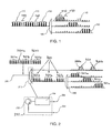
- the bands 110 and 120 are separated by a band 139 corresponding to two channels, but which is not used to transmit signals.
- the bands 120 and 130 are separated by a band 140 corresponding to two channels, but which is not used to transmit signals. Indeed, if we use equipment ordinary strip demultiplexing, strip extraction 110, 120, 130 does cannot be performed without having to sacrifice so-called inter-band channels which are between bands 110 and 120, and between bands 120 and 130. This is due to the large proximity to contiguous wavelengths that can be transported with mode says DWDM (involving spectral separations between channels of 100 GHz, 50 GHz even 25 GHz), and the inherent limitations of the power of spectral discrimination (also called selectivity) of ordinary tape demultiplexing equipment, such as than the demultiplexer 100.
- the bandwidth of the ordinary demultiplexer100 is illustrated by a trapezoid 150 having sides whose slope is not sufficiently steep. This bandwidth is wide enough to cover the channels with a length band of waves (four channels in this example) but has insufficient selectivity for effectively eliminate the inter-band channels constituting bands 139 and 140. These therefore, inter-band channels cannot be used, which reduces significant transport capacity on optical fiber.
- the object of the invention is to provide a system of optical demultiplexing allowing the effective use of these wavelengths inter-bands that would otherwise be lost.
- the system according to the invention makes it possible to use all the channels and in particular the channels conventionally called inter-band that were not used to transmit signals. These channels become usable in particular for network management and wavelength bands, because the system according to the invention makes it possible to obtain sufficient selectivity, while comprising only simple means and few expensive in each of the two floors.
- the first stage consists of a periodic strip deinterlacer, 210, which is intended to separate the two combs 320 and 321.
- a first exit from the demultiplexer 210 provides the comb 320 (bands 320a and 320b) which includes all inter-band channels. These channels are extracted but remain multiplexed in a same multiplex, in this first example.
- the two bands 320a and 320b can be used to transport signals, but not separately.
- a second exit of the deinterlacer 210 provides the comb 321 which includes all the channels used to transport information.
- the strip deinterlacer 210 preferably consists a periodic filter (or a cascade of periodic filters) with selectivity sufficient to effectively attenuate bands 320a and 320b of inter-band channels in the multiplex (including bands 321a, 321b, 321c) supplied on the second exit.
- the second stage consists of a periodic strip demultiplexer, 240. It has three outputs providing bands 213a, 321 b, 321 c separately.
- the demultiplexer constituting the second stage 240 can be without disadvantage a ordinary demultiplexer of contiguous wavelength bands with low selectivity spectral since the inter-band channels (bands 320a and 320b) have been previously extracted with great selectivity by the first stage 210.
- the production of the deinterlacer on stage 210 calls on techniques known to those skilled in the art. It is however detailed on an enlarged part of FIG. 2. It comprises a circulator 252 having an input connected to the fiber 205, and a first output connected to a periodic optical filter 254, for example a so-called filter Fabry-Perot.
- the spectral separation power of the filter 254 must be sufficient to allow the extraction of bands 320a, 320b of inter-band channels. These bands appear on output 256 of the periodic filter 254.
- a second output 258 of circulator 252 constitutes the second output of the deinterlacer 210, providing the bands 321a, 321b, 321c.
- the circulator 252 being a component expensive, it can advantageously be replaced by an insulator followed by a simple coupler.
- FIG. 3 essentially repeats the content of FIG. 2. It represents a demultiplexing system for the case where the two bands of inter-band channels, 320a and 320b, are used separately.
- this second embodiment includes a periodic strip demultiplexer, 360, having an input connected to the first output of the deinterlacer 210, and having two outputs for separately extracting the bands 320a and 320b which are also used to transport signals.
- each of the periodic band demultiplexers, 240 and 360 includes a periodic filter consisting of deposits in thin layers.
- the invention allows that the inter-band channels can be reused when they were usually unusable.
- these channels are used to control the network itself carrying all the information necessary for its proper functioning and to keep it at its optimum level of performance.
- rigorous management is essential for effective use of these. This management requires a channel or channels of controls that advantageously use reusable inter-band wavelengths by implementing the invention.
- inter-band channels which is always shown as being two in Figures 1 to 3 used to describe the prior art and the invention, can obviously be different from this number and that it is only a particular example.
- a demultiplexer bands, 240 which authorizes it because it is sufficiently selective, or because the choice of wavelengths allow this due to sufficient spectral spacing.
Landscapes
- Engineering & Computer Science (AREA)
- Computer Networks & Wireless Communication (AREA)
- Signal Processing (AREA)
- Optical Communication System (AREA)
Applications Claiming Priority (4)
| Application Number | Priority Date | Filing Date | Title |
|---|---|---|---|
| FR0112448 | 2001-09-27 | ||
| FR0112448A FR2830144A1 (fr) | 2001-09-27 | 2001-09-27 | Systeme de demultiplexage optique de bandes de longueurs d'ondes |
| FR0113102 | 2001-10-11 | ||
| FR0113102A FR2830145B1 (fr) | 2001-09-27 | 2001-10-11 | Systeme de demultiplexage optique de bandes de longueurs d'ondes |
Publications (1)
| Publication Number | Publication Date |
|---|---|
| EP1300975A1 true EP1300975A1 (de) | 2003-04-09 |
Family
ID=26213198
Family Applications (1)
| Application Number | Title | Priority Date | Filing Date |
|---|---|---|---|
| EP02292364A Withdrawn EP1300975A1 (de) | 2001-09-27 | 2002-09-26 | Optisches System zum Demultiplexen von Wellenlängenbandern |
Country Status (6)
| Country | Link |
|---|---|
| US (1) | US7085447B2 (de) |
| EP (1) | EP1300975A1 (de) |
| JP (1) | JP2005504478A (de) |
| CN (1) | CN1301602C (de) |
| FR (1) | FR2830145B1 (de) |
| WO (1) | WO2003028263A1 (de) |
Families Citing this family (14)
| Publication number | Priority date | Publication date | Assignee | Title |
|---|---|---|---|---|
| US7725315B2 (en) * | 2003-02-21 | 2010-05-25 | Qnx Software Systems (Wavemakers), Inc. | Minimization of transient noises in a voice signal |
| US7949522B2 (en) | 2003-02-21 | 2011-05-24 | Qnx Software Systems Co. | System for suppressing rain noise |
| US7885420B2 (en) * | 2003-02-21 | 2011-02-08 | Qnx Software Systems Co. | Wind noise suppression system |
| US7895036B2 (en) * | 2003-02-21 | 2011-02-22 | Qnx Software Systems Co. | System for suppressing wind noise |
| US8073689B2 (en) * | 2003-02-21 | 2011-12-06 | Qnx Software Systems Co. | Repetitive transient noise removal |
| US8326621B2 (en) | 2003-02-21 | 2012-12-04 | Qnx Software Systems Limited | Repetitive transient noise removal |
| US8271279B2 (en) | 2003-02-21 | 2012-09-18 | Qnx Software Systems Limited | Signature noise removal |
| CN1866808B (zh) * | 2005-05-21 | 2010-04-28 | 华为技术有限公司 | 一种波分复用系统的复用/解复用方法和装置 |
| CN100549741C (zh) * | 2006-08-21 | 2009-10-14 | 中兴通讯股份有限公司 | 一种无黑波长的分组滤波装置及其分组滤波方法 |
| JP2008259129A (ja) * | 2007-04-09 | 2008-10-23 | Nippon Telegr & Teleph Corp <Ntt> | 光クロスコネクト装置を用いた光ネットワークシステム |
| JP2008259132A (ja) * | 2007-04-09 | 2008-10-23 | Nippon Telegr & Teleph Corp <Ntt> | 光クロスコネクトシステム及び光クロスコネクトシステムにおける信号制御方法 |
| JP2008259134A (ja) * | 2007-04-09 | 2008-10-23 | Nippon Telegr & Teleph Corp <Ntt> | 波長選択スイッチ及び光クロスコネクト装置及び波長選択方法及び光クロスコネクト装置における信号制御方法 |
| US20100260500A1 (en) * | 2009-04-08 | 2010-10-14 | Nec Laboratories America Inc | Mult9-degree wavelength cross-connect using bidirectional wavelength selective switch |
| CN120237516B (zh) * | 2025-05-30 | 2025-08-08 | 浙江大学杭州国际科创中心 | 一种多波长窄线宽激光器 |
Citations (7)
| Publication number | Priority date | Publication date | Assignee | Title |
|---|---|---|---|---|
| EP0874489A2 (de) * | 1997-04-25 | 1998-10-28 | Jds Fitel Inc. | Verfahren und Vorrichtung für das Demultiplexen optischer Signale |
| US6067178A (en) * | 1997-09-16 | 2000-05-23 | Oplink Communications, Inc. | Multiple wavelength division multiplexer with reduced loss |
| EP1043859A2 (de) * | 1999-04-05 | 2000-10-11 | Kabushiki Kaisha Toshiba | Knoteneinrichtung mit optischem Dropp-and-Add-Multiplexer |
| WO2001005082A1 (en) * | 1999-07-13 | 2001-01-18 | Jds Uniphase Corporation | Method and devices for multiplexing and de-multiplexing multiple wavelengths |
| WO2001016558A1 (en) * | 1999-09-01 | 2001-03-08 | Avanex Corporation | Dense wavelength division multiplexer utilizing an asymmetric pass band interferometer |
| US6208444B1 (en) * | 1996-10-29 | 2001-03-27 | Chorum Technologies Inc. | Apparatus for wavelength demultiplexing using a multi-cavity etalon |
| WO2001041347A1 (en) * | 1999-11-30 | 2001-06-07 | Corning Incorporated | Narrow band wavelength division multiplexer and method of multiplexing optical signals |
Family Cites Families (2)
| Publication number | Priority date | Publication date | Assignee | Title |
|---|---|---|---|---|
| CA2203729C (en) * | 1997-04-25 | 2001-04-17 | Jds Fitel Inc. | Method and circuit for demultiplexing an optical signal |
| FR2818080B1 (fr) * | 2000-12-07 | 2003-03-28 | Cit Alcatel | Systeme de demultiplexage/multiplexage en bandes entrelacees |
-
2001
- 2001-10-11 FR FR0113102A patent/FR2830145B1/fr not_active Expired - Lifetime
-
2002
- 2002-09-26 US US10/491,147 patent/US7085447B2/en not_active Expired - Lifetime
- 2002-09-26 JP JP2003531653A patent/JP2005504478A/ja active Pending
- 2002-09-26 CN CNB028214072A patent/CN1301602C/zh not_active Expired - Fee Related
- 2002-09-26 WO PCT/FR2002/003280 patent/WO2003028263A1/fr not_active Ceased
- 2002-09-26 EP EP02292364A patent/EP1300975A1/de not_active Withdrawn
Patent Citations (7)
| Publication number | Priority date | Publication date | Assignee | Title |
|---|---|---|---|---|
| US6208444B1 (en) * | 1996-10-29 | 2001-03-27 | Chorum Technologies Inc. | Apparatus for wavelength demultiplexing using a multi-cavity etalon |
| EP0874489A2 (de) * | 1997-04-25 | 1998-10-28 | Jds Fitel Inc. | Verfahren und Vorrichtung für das Demultiplexen optischer Signale |
| US6067178A (en) * | 1997-09-16 | 2000-05-23 | Oplink Communications, Inc. | Multiple wavelength division multiplexer with reduced loss |
| EP1043859A2 (de) * | 1999-04-05 | 2000-10-11 | Kabushiki Kaisha Toshiba | Knoteneinrichtung mit optischem Dropp-and-Add-Multiplexer |
| WO2001005082A1 (en) * | 1999-07-13 | 2001-01-18 | Jds Uniphase Corporation | Method and devices for multiplexing and de-multiplexing multiple wavelengths |
| WO2001016558A1 (en) * | 1999-09-01 | 2001-03-08 | Avanex Corporation | Dense wavelength division multiplexer utilizing an asymmetric pass band interferometer |
| WO2001041347A1 (en) * | 1999-11-30 | 2001-06-07 | Corning Incorporated | Narrow band wavelength division multiplexer and method of multiplexing optical signals |
Also Published As
| Publication number | Publication date |
|---|---|
| CN1301602C (zh) | 2007-02-21 |
| US20050238283A1 (en) | 2005-10-27 |
| JP2005504478A (ja) | 2005-02-10 |
| WO2003028263A1 (fr) | 2003-04-03 |
| US7085447B2 (en) | 2006-08-01 |
| CN1579061A (zh) | 2005-02-09 |
| FR2830145A1 (fr) | 2003-03-28 |
| FR2830145B1 (fr) | 2004-04-16 |
Similar Documents
| Publication | Publication Date | Title |
|---|---|---|
| EP0677936B1 (de) | Wiederkonfigurierbares optisches Mehrwellenlängen-Ringnetzwerk | |
| EP1300975A1 (de) | Optisches System zum Demultiplexen von Wellenlängenbandern | |
| FR2738432A1 (fr) | Composant optique adapte a la surveillance d'une liaison multilongueur d'onde et multiplexeur a insertion-extraction utilisant ce composant, application aux reseaux optiques | |
| EP0730173A1 (de) | Optischer Multiplexer mit Einfügung und Ausblendung von Kanälen und hoher Isolation | |
| EP0838918B1 (de) | Vorrichtung zum Ein-und Ausfügen von Wellenlängenmultiplexkanälen | |
| JP2000115134A (ja) | 広帯域高密度波長分割多重システムに対するスケ―ラブル光デマルチプレキシング装置 | |
| US20020135838A1 (en) | Dynamic wavelength add/drop multiplexer for UDWDM optical communication system | |
| EP1248336A2 (de) | Verfahren und Vorrichtung zur Wellenlängenkonversion | |
| EP0677935A1 (de) | Ringnetzarchitektur mit Übertragung im Mehrfachzugriff durch spektrale Leitweglenkung | |
| JP2001217777A (ja) | 光波長分岐/挿入マルチプレクサ及びそれに使用されるフィルタ要素 | |
| FR2762170A1 (fr) | Dispositif d'amplification optique capable de detecter au moins un signal parmi des signaux optiques individuels | |
| EP1213866B1 (de) | Verschachtelte Banden Demultiplex-Multiplex-System | |
| FR2829327A1 (fr) | Reseau en anneau realise a partir d'un bus optique double | |
| EP0697800A1 (de) | Optische Rangierverteiler | |
| EP1355441A1 (de) | Verfahren unf Vorrichtung zum steuern der Übertragung optischer Signale | |
| EP1398896A1 (de) | Frequenzkamm für ein Netzwerk mit optischer Frequenzmultiplexierung | |
| EP1315320A2 (de) | Faseroptisches Übertragungssystem mit gemeinsamem Takt | |
| EP1303161A1 (de) | Frequenzselektiver Schalter und diesen enthaltende optische Verzögerungsschaltung | |
| FR2830144A1 (fr) | Systeme de demultiplexage optique de bandes de longueurs d'ondes | |
| EP2160045B1 (de) | Knoten zur Kommunikation von optischen Paketen | |
| EP1657840B1 (de) | DWDM-Kommunikationsnetz mit periodischer Wellenlängen-Multiplexierung | |
| FR3027174A1 (fr) | Dispositif, systeme et procede emetteur-recepteur optoelectronique wdm en cascade | |
| EP1273119A1 (de) | Lichtwellenleiter-übertragungseinrichtung mit wellenlängenmultiplex | |
| EP2282430B1 (de) | Vorrichtung zum Mehrwege-Abzweigen von WDM-Kanälen | |
| EP1492380A1 (de) | Konfigurierbare, optische, signalverarbeitende Vorrichtung mit Breitbandquellen |
Legal Events
| Date | Code | Title | Description |
|---|---|---|---|
| PUAI | Public reference made under article 153(3) epc to a published international application that has entered the european phase |
Free format text: ORIGINAL CODE: 0009012 |
|
| AK | Designated contracting states |
Kind code of ref document: A1 Designated state(s): AT BE BG CH CY CZ DE DK EE ES FI FR GB GR IE IT LI LU MC NL PT SE SK TR Designated state(s): AT BE BG CH CY CZ DE DK EE ES FI FR GB GR IE IT LI LU MC NL PT SE SK TR |
|
| AX | Request for extension of the european patent |
Extension state: AL LT LV MK RO SI |
|
| RIN1 | Information on inventor provided before grant (corrected) |
Inventor name: LE SAUZE, NICOLAS Inventor name: BISSON, ARNAUD Inventor name: FAURE, JEAN-PAUL |
|
| 17P | Request for examination filed |
Effective date: 20031009 |
|
| AKX | Designation fees paid |
Designated state(s): AT BE BG CH CY CZ DE DK EE ES FI FR GB GR IE IT LI LU MC NL PT SE SK TR |
|
| 17Q | First examination report despatched |
Effective date: 20040525 |
|
| STAA | Information on the status of an ep patent application or granted ep patent |
Free format text: STATUS: THE APPLICATION IS DEEMED TO BE WITHDRAWN |
|
| 18D | Application deemed to be withdrawn |
Effective date: 20051012 |