EP1301057A1 - Système de localisation, serveur de localisation, station de base et procédé d'estimation de la position d'un terminal - Google Patents
Système de localisation, serveur de localisation, station de base et procédé d'estimation de la position d'un terminal Download PDFInfo
- Publication number
- EP1301057A1 EP1301057A1 EP02022249A EP02022249A EP1301057A1 EP 1301057 A1 EP1301057 A1 EP 1301057A1 EP 02022249 A EP02022249 A EP 02022249A EP 02022249 A EP02022249 A EP 02022249A EP 1301057 A1 EP1301057 A1 EP 1301057A1
- Authority
- EP
- European Patent Office
- Prior art keywords
- terminal
- location
- base stations
- estimating
- positioning server
- Prior art date
- Legal status (The legal status is an assumption and is not a legal conclusion. Google has not performed a legal analysis and makes no representation as to the accuracy of the status listed.)
- Granted
Links
- 238000000034 method Methods 0.000 title claims abstract description 26
- 238000005259 measurement Methods 0.000 claims abstract description 52
- 238000004891 communication Methods 0.000 claims abstract description 14
- 239000000523 sample Substances 0.000 abstract description 6
- 238000010586 diagram Methods 0.000 description 15
- 230000005684 electric field Effects 0.000 description 12
- 238000009795 derivation Methods 0.000 description 3
- 238000011156 evaluation Methods 0.000 description 2
- 239000000284 extract Substances 0.000 description 2
- 238000000605 extraction Methods 0.000 description 2
- 238000012545 processing Methods 0.000 description 2
- 230000005540 biological transmission Effects 0.000 description 1
- 238000013461 design Methods 0.000 description 1
- 238000001514 detection method Methods 0.000 description 1
- 238000002360 preparation method Methods 0.000 description 1
Images




Classifications
-
- H—ELECTRICITY
- H04—ELECTRIC COMMUNICATION TECHNIQUE
- H04W—WIRELESS COMMUNICATION NETWORKS
- H04W64/00—Locating users or terminals or network equipment for network management purposes, e.g. mobility management
-
- G—PHYSICS
- G01—MEASURING; TESTING
- G01S—RADIO DIRECTION-FINDING; RADIO NAVIGATION; DETERMINING DISTANCE OR VELOCITY BY USE OF RADIO WAVES; LOCATING OR PRESENCE-DETECTING BY USE OF THE REFLECTION OR RERADIATION OF RADIO WAVES; ANALOGOUS ARRANGEMENTS USING OTHER WAVES
- G01S5/00—Position-fixing by co-ordinating two or more direction or position line determinations; Position-fixing by co-ordinating two or more distance determinations
- G01S5/0009—Transmission of position information to remote stations
- G01S5/0018—Transmission from mobile station to base station
- G01S5/0036—Transmission from mobile station to base station of measured values, i.e. measurement on mobile and position calculation on base station
-
- G—PHYSICS
- G01—MEASURING; TESTING
- G01S—RADIO DIRECTION-FINDING; RADIO NAVIGATION; DETERMINING DISTANCE OR VELOCITY BY USE OF RADIO WAVES; LOCATING OR PRESENCE-DETECTING BY USE OF THE REFLECTION OR RERADIATION OF RADIO WAVES; ANALOGOUS ARRANGEMENTS USING OTHER WAVES
- G01S5/00—Position-fixing by co-ordinating two or more direction or position line determinations; Position-fixing by co-ordinating two or more distance determinations
- G01S5/02—Position-fixing by co-ordinating two or more direction or position line determinations; Position-fixing by co-ordinating two or more distance determinations using radio waves
- G01S5/0252—Radio frequency fingerprinting
- G01S5/02521—Radio frequency fingerprinting using a radio-map
Definitions
- the present invention relates to a positioning system, a positioning server, a base station and a terminal location estimation method, and in particular, to a method of easily and accurately detecting a location of a mobile terminal for utilizing a radio communication system.
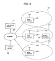
- FIG. 9 is a block diagram showing an example of a configuration of a positioning system in the past.
- reference numeral 21 denotes a positioning server
- 200 denotes the Internet
- 22 denotes a content server
- 23-1 to 23-3 denote base stations
- C-1 to C-3 denote cells covered by the base stations 23-1 to 23-3
- 24 denotes amobile terminal.
- the mobile terminal 24 exists in the cell C2, and performs communication with the positioning server 21 and the content server 22 on the Internet 200 via the base station 23-2.
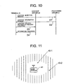
- a procedure shown in FIG. 10 is applicable, for instance.
- the terminal 24 first sends a location detection request message D1 to the positioning server 21.
- the positioning server 21 measures the location of the terminal 24 and sends a location information response message D2 including the location of the terminal 24 to the terminal 24.
- the location of the terminal 24 it maybe the location of the base station to which the terminal 24 is connected, or latitude and longitude at which the terminal 24 exists.
- the terminal 24 sends a location-related information request message D3 including the location obtained from the positioning server 21 to the content server 22.
- the content server 22 provides requested information D4 to the terminal 24 based on the request message D3.
- GPS Global Positioning System
- JP-A- 11-275632 shows a method of improving the resolution of the terminal location without using a system such as the GPS.
- the terminal measures electric field strengths of the radio waves transmitted from a plurality of base stations, and sends the measurement results to the positioning server having an electric field strength database and a base station database, where the positioning server checks values stored in the above-mentioned databases against the measurement results so as to output the terminal location at a resolution smaller than per base station.
- the location of the terminal to be estimated depends on accuracy of electric field strength measurement of the terminal.
- an area estimated to be equal in the electric field strength of the radio wave transmitted from a base station often becomes a plane instead of a point.
- reference numeral 41 denotes the base station
- 40-1 and 40-2 denote the areas determined to be equal in the electric field strength of the radio wave transmitted from the base station 41 respectively.
- the terminal measures the electric field strengths of the received radio waves from a plurality of base stations, and the positioning server estimates the areas in which the terminal exists based on the measurement results and takes the product of the estimated areas. Therefore, the location of the terminal can be estimated at a higher resolution. There is a problem, however, that an resolution of the estimated terminal location becomes rough in the case of a small number of base stations.
- the terminal measures the electric field strengths of received radio waves from a plurality of base stations
- the measurement may take time and the terminal may move during the measurement in the case where the terminal has only one apparatus for measuring the electric field strength.
- the measurement time can be shortened if the terminal has a plurality of measuring apparatuses, there is a possibility that having the plurality of measuring apparatuses may have an impact on the size, cost and power consumption of the terminal.
- An object of the present invention is to provide a positioning system, a positioning server, a base station and a terminal location estimation method capable of accurately estimating the location of a mobile terminal when providing the information services according to the location of the mobile terminal in a radio communication system.
- a positioning system having:
- the above described estimation results contain reception levels and impulse responses in the above described preset areas of radio waves transmitted from the above described base stations.
- the above described estimation results contain reception levels and delay spreads in the above described preset areas of radio waves transmitted from the above described base stations.
- the above described positioning server has estimating means for estimating the radio wave propagation environment between each of the above described preset areas and each of the above described base stations based on at least the location of each of the above described base stations and placement of structures in the above described service area.
- a positioning server connected via a network to a plurality of base stations connectable to a mobile terminal via radio links for estimating a location of the above described terminal in a service area comprised of a plurality of preset areas, wherein:
- a base station connectable to a mobile terminal via a radio link and connected via a network to a positioning server for estimating a location of the above described terminal in a service area comprised of a plurality of preset areas, wherein:
- a terminal location estimation method of a positioning system having a positioning server for estimating a location of a mobile terminal in a service area comprised of a plurality of preset areas, and a plurality of base stations connectable to the above described terminal via radio links and connected to the above described positioning server via a network, wherein:
- the above described estimating step estimates which of the above described preset areas the above described terminal exists in based on results of checking the above described estimation results against the above described measurement results.
- the above described estimating step estimates which of the above described preset areas the above described terminal exists in by evaluating whether or not each of the above described results of checking meets an existence condition set on initialization.
- a radio wave propagation environment between a transmitting point and receiving point connected by a radio link can be modeled with a linear filter, and can be completely described by acquiring amplitude characteristics and phase characteristics (delay characteristics) thereof.
- phase characteristics are reliable information for the purpose of discriminating between the receiving points which are almost equal in the electric field strength of the radio wave transmitted from the transmitting point.
- the results of having the radio wave propagation environment measured by the terminal based on the radio wave transmitted from each of the base stations and the results of having the radio wave propagation environment measured by each of the base stations based on the radio wave transmitted from the terminal are equal. Accordingly, it is possible to shorten the estimation time and suppress the impact of the terminal movement by having the radio wave propagation environment measured by each of the base stations based on the radio wave transmitted from the terminal and estimating the terminal location based on the measurement results.
- FIG. 1 is a block diagram showing a configuration of a positioning system according to an embodiment of the present invention.
- reference symbol A represents a service area
- reference numeral 1 denotes a positioning server
- 2 denotes a content server
- 3-1 to 3-3 denote base stations
- 4 denotes amobile terminal
- 100 denotes the Internet.
- the positioning server 1, the content server 2 and the base stations 3-1 to 3-3 are connected to the Internet 100 respectively, and are capable of performing mutual communication.
- the mobile terminal 4 can obtain the information accumulated in the content server 2 via the base station 3-1, 3-2, 3-3.
- the service area A is a range capable of radio communication by the base stations 3-1 to 3-3, and the terminal 4 performs the communication only in the service area A. That is, the base stations 3-1 to 3-3 provide the terminal 4 in the service area A with the radio communication services.
- the service area A is divided into small areas according to a resolution for estimating the location of the terminal 4.
- the divided areas are location estimation unit areas.
- FIG. 2 is a diagram showing an example of division of the service area A shown in FIG. 1.
- the service area A is divided into a square grid. While the location estimation unit areas are almost in the same shape in this example of division, it is also possible to divide it into the location estimation unit areas in different shapes.
- the location estimation unit areas are defined as three-dimensional space in consideration of a height direction.
- the service area A is divided into a square grid as shown in FIG. 2 to be horizontally and vertically numbered so as to identify each location estimation unit area in the form of (horizontal number, vertical number).
- the size of the location estimation unit area is determined by degree of accuracy with which the location of the terminal 4 is estimated against the entire service area A. In the case of estimating the location of the terminal 4 with high accuracy, the size of each location estimation unit area is rendered smaller, and in the case where rough estimation is sufficient, it is rendered larger.
- the base stations 3-1 to 3-3 are placed to cover the entire service area A irrespective of the above location estimation unit areas.
- they are placed irrespective of the location estimation unit areas while limited by a building structure, placement of utensils and so on.
- the base station 3-1,3-2,3-3 is connected by a radio link to the terminal 4 placed in a cell a, b, c, d covered by the base station.
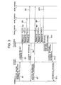
- FIG. 3 is a sequence chart showing operation of the positioning system according to the embodiment of the present invention. A procedure whereby the terminal 4 obtains the information related to its location from the content server 2 will be described by referring to FIGS. 1 to 3.
- the terminal 4 When a user of the terminal 4 needs the information related to its location, the user operates the terminal 4. Then, the terminal 4 sends a location-related information request message B1 including a terminal identifier (hereafter, a terminal ID) to the content server 2. The content server 2 sends a location request message B2 including the terminal ID to the positioning server 1 so as to request the location of the terminal 4 identified by the terminal ID.
- a terminal identifier hereafter, a terminal ID
- the positioning server 1 On receipt of this message B2, the positioning server 1 sends measurement request messages B3 to B5 including the terminal ID to the base stations 3-1 to 3-3. Each of the base stations 3-1 to 3-3 having received the messages B3 to B5 performs preparations such as adjustment of frequencies, for instance, to be able to receive a signal from the terminal 4 identified by the terminal ID. Furthermore, the positioning server 1 sends location information probe message B6 to the terminal 4.
- the terminal 4 On receipt of the location information probe message B6, the terminal 4 transmits a location information response message B7 as a broadcast message.
- a location information response message B7 As a broadcast message.
- each of the base stations 3-1 to 3-3 measures a reception level of the received signal and a channel impulse response, and sends the measurement results to the positioning server 1 as a measurement result message B8, B9, B10 together with the terminal ID.
- the positioning server 1 performs a location estimation unit area estimating process B11 based on the measurement results from the base stations 3-1 to 3-3, and sends to the content server 2 a location response message B12 including the location estimation unit area estimated to have the terminal 4 existing therein and the terminal ID as a response to the location request message B2.
- the content server 2 sends to the terminal 4 information B13 according to the location as a response to the location-related information request message B1.
- the location-related information request message B1 the location information probe message B6 and the information providing message B13 are transferred via the base station 3-1, 3-2, 3-3 to which the terminal 4 is connected, a relay by the base station 3-1, 3-2, 3-3 is omitted in FIG. 3 in order to clarify information flow.
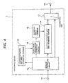
- FIG. 4 is a block diagram showing a configuration example of the positioning server 1 shown in FIG. 1.
- reference numeral 11 denotes an input terminal
- 12 denotes a message controlling portion
- 13 denotes a location estimation unit area information database
- 14 denotes a radio wave propagation estimating portion
- 15 denotes an estimation result database
- 16 denotes a location estimation unit area estimating portion
- 17 denotes a transmitting cue
- 18 denotes an output terminal respectively.
- Control messages to the positioning server 1 are inputted from the input terminal 11.
- the control messages also include those inputted via the Internet 100 and those inputted from an apparatus directly connected to the positioning server 1 such as a keyboard which is not shown.
- the location request message includes the terminal ID and is a positioning request of the location of the terminal 4 identified by the terminal ID.
- the measurement result message includes the terminal ID and information (a transmit frequency of the terminal 4 and so on) measured by the base station 3-1, 3-2, 3-3 and necessary for estimating the terminal location.
- the database update message indicates a change in the location estimation unit area information and is the message for updating the estimation result database 15.
- the location estimation unit area information contains the locations of the base stations 3-1 to 3-3, the locations of newly installed base stations and information on structures such as the buildings and utensils in the service area A.
- the operation of the positioning server 1 is controlled according to the message inputted via the input terminal 11.
- the message controlling portion 12 performs input control on the location request message, input control on the measurement result message, update control on the location estimation unit area information database 13, and update control on the estimation result database 15.
- the input control on the location request message is the control for generating the measurement request message including the terminal ID and sending it to the base stations 3-1 to 3-3 via the transmitting cue 17 and the output terminal 18.
- the input control on the measurement result message is the control for transferring the measurement result included in this message to the location estimation unit area estimating portion 16, estimating the location of the terminal 4 identified by the terminal ID, and sending the estimation result to the content server 2 via the transmitting cue 17 and the output terminal 18.
- the update control on the location estimation unit area information database 13 is the control for updating the location estimation unit area information database 13 when changes in the location estimation unit area information arise such as the location of a newly installed base station and changes in the structures in the service area A.
- the update control on the estimation result database 15 is the control for, when the location estimation unit area information database 13 is updated, updating the estimation result database 15 with a radio wave propagation situation estimated by the radio wave propagation estimating portion 14 based on the location estimation unit area information.
- the radio wave propagation estimating portion 14 estimates parameters such as received signal levels and delay spreads in each location estimation unit area of radio waves transmitted from the base stations 3-1 to 3-3, according to a predetermined algorithm, based on the location estimation unit area information accumulated in the location estimation unit area information database 13, and outputs the estimated parameters to the estimation result database 15.
- radio wave propagation estimating portion 14 algorithms used in the radio wave propagation estimating portion 14 include a ray tracing method shown in John W. McKown and R. Lee Hamilton, Kr., "Ray Tracing as a Design Tool for Radio Networks” (IEEE Network Magazine, pp. 27 to 30, Nov. 1991) for instance.
- the radio wave propagation estimating portion 14 uses the ray tracing method to consider the impact of the structures constituting the propagation environment such as the buildings and utensils on the radio wave transmitted from each base station so as to estimate the received signal levels, delay spreads and so on which are the parameters showing the propagation environment in each location estimation unit area in the service area A shown in FIG. 2 and output them to the estimation result database 15.
- the estimation result database 15 stores the estimation results estimated by the radio wave propagation estimating portion 14 such as the received signal levels and delay spreads in each location estimation unit area in the service area A.
- the location estimation unit area information which contains the information on the structures such as the buildings and utensils, the locations of the base stations 3-1 to 3-3 and so on is accumulated in the location estimation unit area information database 13, it is also possible to describe the location estimation unit area information in the message inputted to the message controlling portion 12 which directly inputs it to the radio wave propagation estimating portion 14, and in this case, the location estimation unit area information database 13 is no longer necessary.
- FIG. 5 is a diagram showing the contents stored in the estimation result database 15 shown in FIG. 4.
- the estimation result database 15 manages a table showing each location estimation unit area in the service area A with vertical and horizontal numbers, and stores the estimation results such as the received signal level (reception level) and delay spread in each location estimation unit area of the radio wave transmitted from each base station.
- this table shows an example of three base stations #1 to #3, it is also possible to increase the number of the base stations to be stored.
- the location estimation unit area estimating portion 16 compares these measurement results to the estimation results on the base station managed by the table of the estimation result database 15 so as to estimate the location of the terminal 4.
- FIG. 6 is a flowchart showing an operation example of the location estimation unit area estimating portion 16 in FIG. 4
- FIG. 7 is a diagram showing the configuration example of a processing table to be used in the location estimation unit area estimating portion 16 in FIG. 4. Operation of estimating the location of the terminal 4 by the location estimation unit area estimating portion 16 will be described by referring to these FIGS. 1 to 7.
- the location estimation unit area estimating portion 16 assigns the number of base stations to be considered to a variable N_AP, and also sets a condition for determining that the terminal 4 exists (existence condition) (step S1 in FIG. 6 (initialization step)).
- the existence condition is the condition for estimating which location estimation unit area the terminal 4 exists in, and it uses a difference between data stored in the estimation result database 15 and the measurement results for instance.
- the condition for the terminal 4 to exist in one location estimation unit area (i, j) is set as follows.
- the absolute value of the difference between the reception level (see FIG. 5) in the location estimation unit area (i, j) and the reception level of the measurement results is within 3 dB, and the absolute value of the difference between the delay spread (see FIG. 5) in the location estimation unit area (i, j) and the delay spread of the measurement results is within 20 microseconds.
- the location estimation unit area estimating portion 16 subtracts 1 from N_AP, and sets the base station to be evaluated (step S2 in FIG. 6 (base station update step)), and prepares to evaluate the existence condition based on the measurement results of the set base station and the estimation results in each location estimation unit area (step S3 in FIG. 6 (1 base station measurement result extraction step)).
- the location estimation unit area estimating portion 16 evaluates the existence condition, and extracts the location estimation unit area(s) in which the terminal 4 may exist (step S4 in FIG. 6 (1 base station candidate area derivation step)).
- step S5 in FIG.6 base station evaluation completion determination step
- step S5 in FIG.6 base station evaluation completion determination step
- step S5 in FIG.6 base station evaluation completion determination step
- the location estimation unit area estimating portion 16 In the base station evaluation completion determination step (step S5 in FIG. 6), the location estimation unit area estimating portion 16 generates the table as shown in FIG. 7 immediately before proceeding to the next step. While this table shows a case where the number of the base stations is 3, it may be extended to the cases where the number of the base stations is different.
- the table shown in FIG. 7 indicates each location estimation unit area with vertical and horizontal numbers.
- the location estimation unit area estimating portion 16 extracts the reception level and the delay spread in each location estimation unit area of the radio wave transmitted from each of the base stations #1 to #3 from the table shown in FIG. 5 stored in the estimation result database 15, and acquires the differences between the extracted estimation results and the measurement results of each of the base stations #1 to #3 (step S3 in FIG. 6 (1 base station measurement result extraction step)).
- the location estimation unit area estimating portion 16 evaluates whether or not the terminal 4 exists in each location estimation unit area seen from each of the base stations #1 to #3 based on the obtained results and the existence condition, so as to input "1" in an existence determination line in the case where it may exist and input "0" therein in the case where it does not exist (step S4 in FIG. 6 (1 base station candidate area derivation step)). In the table shown in FIG. 7, the location estimation unit area estimating portion 16 assigns "999" to indicate that it is unmeasurable in the case where, for instance, the terminal 4 is too far from the base station #3 to have the radio waves reach there.
- the location estimation unit area estimating portion 16 determines whether or not to change the existence condition based on the number of the detected location estimation unit areas (step S7 in FIG. 6 (location estimation completion determination step)).
- the change in the existence condition is implemented, for instance, by changing it to be more strict in the case where a large number of the location estimation unit areas in which the terminal 4 may exist are detected, and changing it to be less strict in the case where no location estimation unit areas in which the terminal 4 may exist is detected. If the number of the detected location estimation unit areas in which the terminal 4 may exist is as required and sufficient, this flow is finished and the portion 16 outputs the detected location estimation unit area(s).
- the location estimation unit area estimating portion 16 On determining that the existence condition is to be changed, the location estimation unit area estimating portion 16 performs the change in the existence condition as above (step S8 in FIG. 6(existence determination condition update step)), and returns to the 1 base station candidate area derivation step (step S4 in FIG. 6).
- FIG. 8 is a block diagram showing a configuration example of each of the base stations 3-1 to 3-3 in FIG. 1.
- reference numeral 31 denotes an input-output terminal
- 32 denotes a message controlling portion
- 33 denotes a main signal radio portion
- 331 denotes a transmitting and receiving controlling portion
- 333 denotes a main signal receiving portion
- 334 denotes a transmitting portion
- 332 denotes a switch
- 335 denotes a transmitting and receiving antenna
- 34 denotes a location measurement radio portion
- 341 denotes a location estimation receiving portion
- 342 denotes a receiving antenna respectively.
- each of the base stations 3-1 to 3-3 is the base station 3.
- the input-output terminal 31 is connected to the Internet 100, and exchanges packets with the positioning server 1 and the content server 2.
- the message controlling portion 32 converts a format for relaying between a radio communication system and awire communication system (the Internet 100), analyzes amessage from the input-output terminal 31, and adequately starts the main signal radio portion 33 and the location measurement radio portion 34.
- the transmitting and receiving controlling portion 331 controls the transmitting portion 334 and performs retransmitting control of the radio communication system.
- the station 3 has two systems of the location measurement radio portion 34 and the main signal radio portion 33.
- the location measurement radio portion 34 is comprised of the location estimation receiving portion 341 and the receiving antenna 342, and receives the location information response message transmitted from the terminal 4 based on settings from the message controlling portion 32 and measures the received signal level, delay spread and so on which are the parameters showing the radio wave propagation environment (radio wave propagation characteristics) so as to output them to the message controlling portion 32 as the measurement results.
- the main signal radio portion 33 is comprised of the transmitting and receiving controlling portion 331, the transmitting portion 334, the main signal receiving portion 333, the switch 332 and the transmitting and receiving antenna 335, and relays the packets such as user data between the terminal 4 connected to the base station 3 and the Internet 100.
- the message controlling portion 32 On having the packet to the terminal 4 inputted from the input-output terminal 31, the message controlling portion 32 outputs it to the transmitting and receiving controlling portion 331.
- the transmitting and receiving controlling portion 331 notifies the transmitting portion 334 and the switch 332 that there is the transmitting packet and prepares for transmitting, and then transmits the packet via the transmitting portion 334, switch 332 and antenna 335.
- the switch 332 normally has the main signal receiving portion 333 and the antenna 335 connected thereto.
- the packet transmitted from the terminal 4 is received by the transmitting and receiving controlling portion 331 via the antenna 335, switch 332 and main signal receiving portion 333. Furthermore, this packet is transferred to the Internet 100 via the message controlling portion 32 and input-output terminal 31.
- the operation of the base station 3 will be described by using FIG. 3.
- the location-related information request message B1 transmitted from the terminal 4 is received by the base station 3 to which the terminal 4 is connected.
- the message B1 is supplied to the transmitting and receiving controlling portion 331 via the antenna 335, switch 332 and main signal receiving portion 333.
- the transmitting and receiving controlling portion 331 performs retransmitting control for a transmission error in the message B1, and transfers the correctly received message B1 to the message controlling portion 32.
- the message controlling portion 32 converts the format of the message B1 into the format used on the Internet 100, and then sends it to the content server 2 via the input-output terminal 31.
- the measurement request message B3, B4, B5 sent from the positioning server 1 is received by the message controlling portion 32 via the input-output terminal 31.
- the message controlling portion 32 analyzes this message, and sets a frequency in the location measurement radio portion 34 so that it can receive the location information response message B7 transmitted from the terminal identified by the terminal ID (the terminal 4 in this example).
- the location information probe message B6 sent from the positioning server 1 to the terminal 4 is transferred to the base station 3 to which the terminal 4 is connected, and then is transferred to the terminal 4 via the input-output terminal 31, message controlling portion 32, transmitting and receiving controlling portion 331, transmitting portion 334, switch 332 and antenna 335.
- the location information response message B7 transmitted as the broadcast message from the terminal 4 is received by the location estimation receiving portion 341.
- the location estimation receiving portion 341 measures the parameters showing the propagation environment for estimating the location of the terminal 4, and transfers them to the message controlling portion 32.
- the message controlling portion 32 transfers the inputted parameters as the measurement result message B8, B9, B10 to the positioning server 1.
- the information providing message B13 sent from the content server 2 is transferred to the base station 3 to which the terminal 4 is connected, and then is transferred to the terminal 4 on the same route as the location information probe message B6.
- the location estimation receiving portion 341 estimates the parameters such as the received signal level and the delay spread obtained from the channel impulse response based on the location information response message B7 transmitted from the terminal 4. For this estimation, a preamble signal added to the radio packet may be used for instance. With the preamble signal, the portion 341 measures the received signal level and estimates the channel impulse response for the sake of setting of an equalizer for equalizing a distortion due to multi-path phasing in order to correctly demodulate the packet. The parameters for estimating the location is extracted based on these results.
- the positioning server 1 has the radio wave propagation estimating portion 14 which stores the estimation results in the estimation result database 15 according to change in structures in the service area A and so on, so that it can promptly cope with addition of a new base station, the change in structures and so on.
- the base station 3 has the radio system for detecting the location (the location measurement radio portion 34), it is possible to accurately estimate the location of the terminal 4 without having an impact on the terminal 4 connected thereto.
Landscapes
- Engineering & Computer Science (AREA)
- Physics & Mathematics (AREA)
- General Physics & Mathematics (AREA)
- Radar, Positioning & Navigation (AREA)
- Remote Sensing (AREA)
- Computer Networks & Wireless Communication (AREA)
- Signal Processing (AREA)
- Mobile Radio Communication Systems (AREA)
- Position Fixing By Use Of Radio Waves (AREA)
Applications Claiming Priority (2)
| Application Number | Priority Date | Filing Date | Title |
|---|---|---|---|
| JP2001307008A JP2003116164A (ja) | 2001-10-03 | 2001-10-03 | 測位システム、測位サーバ、無線基地局及びそれに用いる端末位置推定方法 |
| JP2001307008 | 2001-10-03 |
Publications (2)
| Publication Number | Publication Date |
|---|---|
| EP1301057A1 true EP1301057A1 (fr) | 2003-04-09 |
| EP1301057B1 EP1301057B1 (fr) | 2009-05-27 |
Family
ID=19126542
Family Applications (1)
| Application Number | Title | Priority Date | Filing Date |
|---|---|---|---|
| EP02022249A Expired - Lifetime EP1301057B1 (fr) | 2001-10-03 | 2002-10-02 | Système de localisation, serveur de localisation et procédé d'estimation de la position d'un terminal |
Country Status (5)
| Country | Link |
|---|---|
| US (1) | US7013150B2 (fr) |
| EP (1) | EP1301057B1 (fr) |
| JP (1) | JP2003116164A (fr) |
| CN (1) | CN1225920C (fr) |
| DE (1) | DE60232428D1 (fr) |
Cited By (7)
| Publication number | Priority date | Publication date | Assignee | Title |
|---|---|---|---|---|
| WO2005084206A2 (fr) | 2004-02-27 | 2005-09-15 | Airespace, Inc. | Fin selective de connexions sans fil pour rafraichir des informations de signal dans une infrastructure de localisation de noeuds sans fil |
| EP1492362A3 (fr) * | 2003-06-24 | 2006-05-17 | Samsung Electronics Co., Ltd. | Dispositif et procédé de recherche d'information de localisation au moyen de technologies de détection de localisation diverses dans une station de communication mobile |
| WO2011059481A1 (fr) | 2009-11-12 | 2011-05-19 | Cisco Technology, Inc. | Suivi de localisation à l'aide de messages de réponse identifiant un dispositif suivi dans un réseau sans fil |
| EP2458918A4 (fr) * | 2009-07-20 | 2014-03-26 | Zte Corp | Procédé et appareil de transmission d'informations de localisation |
| WO2015127423A1 (fr) * | 2014-02-24 | 2015-08-27 | Skyhook Wireless, Inc. | Localisation certifiée pour dispositifs mobiles |
| US9743250B2 (en) | 2013-10-28 | 2017-08-22 | Empire Technology Development Llc | Determination of a location of a communication device |
| RU2756916C2 (ru) * | 2017-04-11 | 2021-10-07 | Керлинк | Способ, устройство и компьютерный программный продукт для определения географического местоположения радиопередатчика |
Families Citing this family (59)
| Publication number | Priority date | Publication date | Assignee | Title |
|---|---|---|---|---|
| US6700534B2 (en) * | 2000-10-16 | 2004-03-02 | Scott C. Harris | Position privacy in an electronic device |
| US20050003828A1 (en) * | 2002-04-09 | 2005-01-06 | Sugar Gary L. | System and method for locating wireless devices in an unsynchronized wireless environment |
| AU2003259781A1 (en) * | 2002-08-13 | 2004-02-25 | Vanu, Inc. | Convolutional decoding |
| WO2004019579A1 (fr) | 2002-08-13 | 2004-03-04 | Vanu, Inc. | Decodage adaptatif au bruit |
| DE60238980D1 (de) * | 2002-08-28 | 2011-03-03 | Cambridge Positioning Sys Ltd | Verbesserungen in Funkortungsystemen |
| US20040209580A1 (en) * | 2002-11-15 | 2004-10-21 | Vanu Bose | Communications system |
| WO2004052027A2 (fr) * | 2002-11-27 | 2004-06-17 | Cognio, Inc | Systeme et procede de localisation de sources de signaux radio sans fil inconnus |
| US20050021976A1 (en) * | 2003-06-23 | 2005-01-27 | Nokia Corporation | Systems and methods for controlling access to an event |
| US8712428B2 (en) * | 2003-07-19 | 2014-04-29 | Polaris Wireless, Inc. | Location estimation of wireless terminals through pattern matching of deduced signal strengths |
| KR100621955B1 (ko) * | 2003-07-31 | 2006-09-13 | 가부시키가이샤 엔.티.티.도코모 | 무선 제어 장치 및 이동 통신 방법 |
| KR20080102264A (ko) * | 2003-12-08 | 2008-11-24 | 콸콤 인코포레이티드 | 총 수신 전력을 이용한 과도 지연 추정 |
| US20050130675A1 (en) * | 2003-12-16 | 2005-06-16 | Burch Jefferson B. | Wireless probe management system |
| EP1730649A2 (fr) * | 2004-03-05 | 2006-12-13 | Vanu, Inc. | Reduction des effets de gigue |
| CA2568307A1 (fr) * | 2004-06-09 | 2005-12-29 | Vanu, Inc. | Reduction du cout de la liaison terrestre cellulaire |
| EP1757033A4 (fr) * | 2004-06-09 | 2009-04-22 | Vanu Inc | Reduction de bande passante d'une liaison terrestre |
| US20060009236A1 (en) * | 2004-06-09 | 2006-01-12 | Vanu Bose | Determining a location |
| CN100370875C (zh) * | 2004-08-31 | 2008-02-20 | 华为技术有限公司 | 一种区域变化类位置信息请求中通知/验证的处理方法 |
| KR100605980B1 (ko) * | 2005-01-04 | 2006-07-31 | 삼성전자주식회사 | 휴대 인터넷 신호를 이용한 위치 측정 시스템 및 방법 |
| CN100431370C (zh) * | 2005-05-11 | 2008-11-05 | 中兴通讯股份有限公司 | 模拟移动台系统、模拟移动台定位测试系统及测试方法 |
| US7904096B2 (en) * | 2005-09-06 | 2011-03-08 | O2Micro International Limited | GPS application using network assistance |
| WO2007044501A2 (fr) * | 2005-10-07 | 2007-04-19 | Vanu, Inc. | Decodage de codes de walsh |
| US7812718B1 (en) | 2005-11-21 | 2010-10-12 | The Hong Kong University Of Science And Technology | Distributed position estimation for wireless sensor networks |
| JP2007150435A (ja) * | 2005-11-24 | 2007-06-14 | Radioware:Kk | 通信システム |
| FI118715B (fi) * | 2005-12-07 | 2008-02-15 | Ekahau Oy | Paikannustekniikka |
| JP5228276B2 (ja) * | 2006-01-12 | 2013-07-03 | 沖電気工業株式会社 | 位置推定システム |
| JP4767737B2 (ja) * | 2006-03-31 | 2011-09-07 | 株式会社エヌ・ティ・ティ・ドコモ | 位置推定システム及び位置推定方法 |
| US20080076406A1 (en) * | 2006-09-22 | 2008-03-27 | Vanu, Inc. | Wireless Backhaul |
| US20080076435A1 (en) * | 2006-09-22 | 2008-03-27 | Vanu, Inc. | Wireless Backhaul |
| US7764230B2 (en) * | 2007-03-13 | 2010-07-27 | Alcatel-Lucent Usa Inc. | Methods for locating transmitters using backward ray tracing |
| WO2009033001A2 (fr) * | 2007-09-05 | 2009-03-12 | University Of Utah Research Foundation | Distinction d'emplacement robuste utilisant des signatures de lien temporel |
| CN101453695B (zh) * | 2007-11-30 | 2011-04-20 | 华为技术有限公司 | 一种定位测量方法、系统和装置 |
| CN101227731B (zh) * | 2008-02-01 | 2011-01-19 | 中兴通讯股份有限公司 | 一种手机跟踪方法及系统 |
| CN101568062B (zh) * | 2008-04-23 | 2012-11-21 | 华为技术有限公司 | 位置业务的实现方法、系统、定位服务器 |
| JP5255958B2 (ja) * | 2008-09-03 | 2013-08-07 | 株式会社エヌ・ティ・ティ・ドコモ | データベース管理システム、データベース管理方法及びデータベース管理プログラム |
| WO2010030950A2 (fr) * | 2008-09-12 | 2010-03-18 | University Of Utah Research Foundation | Procédé et système de détection de points d'accès sans fil non autorisés en utilisant des décalages d'horloge |
| CN101494901B (zh) * | 2009-02-27 | 2011-01-05 | 华为终端有限公司 | 移动终端的定位方法、定位系统及其通信设备 |
| JP2010268381A (ja) * | 2009-05-18 | 2010-11-25 | Japan Radio Co Ltd | ゲート通過検知システム |
| CN101893699B (zh) * | 2009-05-19 | 2013-10-30 | 晨星软件研发(深圳)有限公司 | 定位方法与定位系统 |
| US8170815B2 (en) * | 2009-06-08 | 2012-05-01 | Rockstar Bidco Lp | RF fingerprinting for location estimation |
| US20110076975A1 (en) * | 2009-09-28 | 2011-03-31 | Electronics And Telecommunications Research Institute | Method and apparatus for wireless location measurement |
| KR20110034570A (ko) * | 2009-09-28 | 2011-04-05 | 한국전자통신연구원 | 무선 측위 방법 및 장치 |
| KR101205719B1 (ko) * | 2009-10-29 | 2012-11-28 | 한국전자통신연구원 | 광선의 경로추적을 위한 3차원 전처리 방법 |
| US8560012B2 (en) * | 2009-11-30 | 2013-10-15 | Panasonic Corporation | Communication device |
| US8818288B2 (en) | 2010-07-09 | 2014-08-26 | University Of Utah Research Foundation | Statistical inversion method and system for device-free localization in RF sensor networks |
| JP5405409B2 (ja) * | 2010-07-30 | 2014-02-05 | 株式会社Nttドコモ | 移動通信方法、測位装置及び無線基地局 |
| JP5093316B2 (ja) * | 2010-09-09 | 2012-12-12 | ソニー株式会社 | 情報処理装置、情報処理方法、情報処理システム、およびプログラム |
| KR101161983B1 (ko) | 2010-10-05 | 2012-07-04 | 주식회사 엘지유플러스 | 이동통신 단말기의 위치 정보를 산출하는 위치 관리 서버 및 그 산출 방법 |
| CN103458500B (zh) * | 2012-06-04 | 2016-08-31 | 华为技术有限公司 | 一种定位用户设备的方法及装置 |
| CN104754728B (zh) * | 2013-12-26 | 2020-03-31 | 华为终端(深圳)有限公司 | 终端定位方法与装置 |
| WO2015139184A1 (fr) * | 2014-03-17 | 2015-09-24 | 华为技术有限公司 | Procédé et dispositif de localisation |
| JP6641778B2 (ja) * | 2015-08-14 | 2020-02-05 | 沖電気工業株式会社 | 位置推定システム、位置推定方法及び無線装置 |
| CN106658702B (zh) * | 2015-11-03 | 2020-05-26 | 大唐移动通信设备有限公司 | 一种定位方法及装置 |
| AU2016371057A1 (en) * | 2015-12-17 | 2018-07-19 | Humatics Corporation | Radio-frequency localization techniques and associated systems, devices, and methods |
| CN107144831A (zh) * | 2017-04-06 | 2017-09-08 | 华东师范大学 | 一种微型低功耗的被动定位系统 |
| CN108872931B (zh) * | 2017-05-12 | 2021-01-29 | 北京神州泰岳软件股份有限公司 | 一种无线网络定位方法及装置 |
| WO2019039096A1 (fr) * | 2017-08-21 | 2019-02-28 | ソニー株式会社 | Dispositif de traitement d'informations, station de base, dispositif terminal et procédé de traitement d'informations |
| JP2018067356A (ja) * | 2018-01-19 | 2018-04-26 | エンパイア テクノロジー ディベロップメント エルエルシー | 通信デバイスのロケーションの決定 |
| JP7081555B2 (ja) * | 2019-04-02 | 2022-06-07 | 日本電信電話株式会社 | 置局支援方法および置局支援システム |
| EP3965340B1 (fr) * | 2020-09-08 | 2024-08-21 | Volkswagen Ag | Noeud d'accès, équipement utilisateur, appareils, procédés et programmes informatiques permettant de déterminer une grille de temps-fréquence et configuration de pilote pour une liaison radio entre deux émetteurs-récepteurs d'un système de communication mobile |
Citations (2)
| Publication number | Priority date | Publication date | Assignee | Title |
|---|---|---|---|---|
| EP0631453A2 (fr) * | 1993-06-21 | 1994-12-28 | Telia Ab | Procédé de localisation de stations mobiles dans un réseau téléphonique numérique |
| EP0780699A1 (fr) * | 1995-12-21 | 1997-06-25 | C. PLATH GmbH | Procédé de localisation en particulier d'émetteur à agilité de fréquence |
Family Cites Families (7)
| Publication number | Priority date | Publication date | Assignee | Title |
|---|---|---|---|---|
| US5717406A (en) * | 1995-06-07 | 1998-02-10 | Sanconix Inc. | Enhanced position calculation |
| US6108555A (en) * | 1996-05-17 | 2000-08-22 | Ksi, Inc. | Enchanced time difference localization system |
| FI974153A7 (fi) * | 1997-11-06 | 1999-05-07 | Nokia Corp | Menetelmä ja järjestely matkaviestimen sijainnin määrittelemiseksi |
| JPH11275632A (ja) | 1998-03-18 | 1999-10-08 | Nippon Telegr & Teleph Corp <Ntt> | 通信装置 |
| US6070083A (en) * | 1998-05-14 | 2000-05-30 | Nortel Networks Corporation | Mobile communication device and communication network for providing location services |
| US6662016B1 (en) * | 2000-05-05 | 2003-12-09 | Openwave Systems, Inc. | Providing graphical location information for mobile resources using a data-enabled network |
| US6681099B1 (en) * | 2000-05-15 | 2004-01-20 | Nokia Networks Oy | Method to calculate true round trip propagation delay and user equipment location in WCDMA/UTRAN |
-
2001
- 2001-10-03 JP JP2001307008A patent/JP2003116164A/ja active Pending
-
2002
- 2002-09-26 US US10/254,772 patent/US7013150B2/en not_active Expired - Fee Related
- 2002-10-02 EP EP02022249A patent/EP1301057B1/fr not_active Expired - Lifetime
- 2002-10-02 DE DE60232428T patent/DE60232428D1/de not_active Expired - Lifetime
- 2002-10-08 CN CNB021457301A patent/CN1225920C/zh not_active Expired - Fee Related
Patent Citations (2)
| Publication number | Priority date | Publication date | Assignee | Title |
|---|---|---|---|---|
| EP0631453A2 (fr) * | 1993-06-21 | 1994-12-28 | Telia Ab | Procédé de localisation de stations mobiles dans un réseau téléphonique numérique |
| EP0780699A1 (fr) * | 1995-12-21 | 1997-06-25 | C. PLATH GmbH | Procédé de localisation en particulier d'émetteur à agilité de fréquence |
Non-Patent Citations (2)
| Title |
|---|
| JUNIUS M ET AL: "New methods for processing GSM radio measurement data: applications for locating, handover, and network management", VEHICULAR TECHNOLOGY CONFERENCE, 1994 IEEE 44TH STOCKHOLM, SWEDEN 8-10 JUNE 1994, NEW YORK, NY, USA,IEEE, 8 June 1994 (1994-06-08), pages 338 - 342, XP010123099, ISBN: 0-7803-1927-3 * |
| KENNEMANN O: "CONTINUOUS LOCATION OF MOVING GSM MOBILE STATIONS BY PATTERN RECOGNITION TECHNIQUES", WIRELESS NETWORKS - CATCHING THE MOBILE FUTURE - IEEE INTERNATIONAL SYMPOSIUM ON PERSONAL, INDOOR AND MOBILE RADIO COMMUNICATIONS AND ICCC REGIONAL MEETING ON WIRELESS COMPUTER NETWORKS. PROCEEDINGS OF WIRELESS NETWORKS CATCHING THE MOBILE FUTURE, XX, vol. 2, 18 September 1994 (1994-09-18), pages 630 - 634, XP001013726 * |
Cited By (13)
| Publication number | Priority date | Publication date | Assignee | Title |
|---|---|---|---|---|
| EP1492362A3 (fr) * | 2003-06-24 | 2006-05-17 | Samsung Electronics Co., Ltd. | Dispositif et procédé de recherche d'information de localisation au moyen de technologies de détection de localisation diverses dans une station de communication mobile |
| EP1719360A4 (fr) * | 2004-02-27 | 2011-12-28 | Airespace Inc | Fin selective de connexions sans fil pour rafraichir des informations de signal dans une infrastructure de localisation de noeuds sans fil |
| WO2005084206A2 (fr) | 2004-02-27 | 2005-09-15 | Airespace, Inc. | Fin selective de connexions sans fil pour rafraichir des informations de signal dans une infrastructure de localisation de noeuds sans fil |
| EP2458918A4 (fr) * | 2009-07-20 | 2014-03-26 | Zte Corp | Procédé et appareil de transmission d'informations de localisation |
| WO2011059481A1 (fr) | 2009-11-12 | 2011-05-19 | Cisco Technology, Inc. | Suivi de localisation à l'aide de messages de réponse identifiant un dispositif suivi dans un réseau sans fil |
| US9055395B2 (en) | 2009-11-12 | 2015-06-09 | Cisco Technology, Inc. | Location tracking using response messages identifying a tracked device in a wireless network |
| US9743250B2 (en) | 2013-10-28 | 2017-08-22 | Empire Technology Development Llc | Determination of a location of a communication device |
| WO2015127423A1 (fr) * | 2014-02-24 | 2015-08-27 | Skyhook Wireless, Inc. | Localisation certifiée pour dispositifs mobiles |
| US9817101B2 (en) | 2014-02-24 | 2017-11-14 | Skyhook Wireless, Inc. | Certified location for mobile devices |
| US10866300B2 (en) | 2014-02-24 | 2020-12-15 | Skyhook Wireless, Inc. | Certified location for mobile devices |
| US11474190B2 (en) | 2014-02-24 | 2022-10-18 | Skyhook Wireless, Inc. | Certified location for mobile devices |
| US11906645B2 (en) | 2014-02-24 | 2024-02-20 | Qualcomm Incorporated | Certified location for mobile devices |
| RU2756916C2 (ru) * | 2017-04-11 | 2021-10-07 | Керлинк | Способ, устройство и компьютерный программный продукт для определения географического местоположения радиопередатчика |
Also Published As
| Publication number | Publication date |
|---|---|
| US20030064733A1 (en) | 2003-04-03 |
| CN1225920C (zh) | 2005-11-02 |
| EP1301057B1 (fr) | 2009-05-27 |
| CN1411289A (zh) | 2003-04-16 |
| US7013150B2 (en) | 2006-03-14 |
| JP2003116164A (ja) | 2003-04-18 |
| DE60232428D1 (de) | 2009-07-09 |
Similar Documents
| Publication | Publication Date | Title |
|---|---|---|
| EP1301057B1 (fr) | Système de localisation, serveur de localisation et procédé d'estimation de la position d'un terminal | |
| JP4100320B2 (ja) | 位置検出システムおよび装置 | |
| US9191912B2 (en) | Systems and methods for location determination | |
| EP1506686B1 (fr) | Determination de position amelioree au sein de systemes de communication sans fil | |
| US8712428B2 (en) | Location estimation of wireless terminals through pattern matching of deduced signal strengths | |
| US20050014518A1 (en) | Location estimation of wireless terminals through pattern matching of deduced and empirical signal-strength measurements | |
| CN107371233B (zh) | 同步信号收发方法及无线通信装置 | |
| KR100960533B1 (ko) | 유피셀 데이터베이스를 이용한 단말 기반의 위치 측정방법, 장치 및 시스템 | |
| US8606275B2 (en) | Method for identifying missing neighbors and for updating current neighbors in wireless networks | |
| MXPA05009418A (es) | Metodo y aparato para desarrollar la determinacion de la posicion en una red de comunicacion inalambrica con repetidoras. | |
| KR20230035712A (ko) | 모션 인디케이터 값들에 기반한 무선 메시 네트워크 내 모션 로컬화 | |
| JP2006515727A (ja) | 無線通信システムにおいて予測電力を用いて送信機を識別する方法および装置 | |
| EP0895600A1 (fr) | Procede et appareil d'estimation par matrice de covariances recourant a une solution de localisation par la methode des moindres carres ponderes | |
| KR100652259B1 (ko) | 중계기를 포함하는 무선 네트워크에 대한 신호 경로 검출 | |
| WO2005029878A2 (fr) | Systeme et procede de fonctionnement pour un systeme de geolocation de superpositions de reseau a repeteurs | |
| WO2001018560A1 (fr) | Estimation de la distance entre un emetteur et un recepteur | |
| KR102748142B1 (ko) | 액세스 포인트의 위치 보정 장치 및 방법 | |
| CN1985185A (zh) | 定位移动终端 | |
| WO2016048370A1 (fr) | Systèmes et procédés de localisation | |
| US20220217545A1 (en) | Station setting support method and station setting support system | |
| EP2203015A1 (fr) | Procédé de génération de zones de coopération dans des réseaux de communication et nýuds de réseau correspondants | |
| JP2007135228A (ja) | 測位システム、測位サーバ、無線基地局及びそれに用いる端末位置推定方法 | |
| KR100567489B1 (ko) | 이동통신시스템에서의 단말기 위치 추정 방법 | |
| KR100664066B1 (ko) | 시분할 복신 방식의 이동통신망에서 단말 위치 추적 시스템 및 그 방법 | |
| Almăjanu et al. | Radio coverage analysis for mobile communication networks using ics telecom |
Legal Events
| Date | Code | Title | Description |
|---|---|---|---|
| PUAI | Public reference made under article 153(3) epc to a published international application that has entered the european phase |
Free format text: ORIGINAL CODE: 0009012 |
|
| 17P | Request for examination filed |
Effective date: 20030121 |
|
| AK | Designated contracting states |
Kind code of ref document: A1 Designated state(s): AT BE BG CH CY CZ DE DK EE ES FI FR GB GR IE IT LI LU MC NL PT SE SK TR Designated state(s): AT BE BG CH CY CZ DE DK EE ES FI FR GB GR IE IT LI LU MC NL PT SE SK TR |
|
| AX | Request for extension of the european patent |
Extension state: AL LT LV MK RO SI |
|
| AKX | Designation fees paid |
Designated state(s): DE FR GB |
|
| 17Q | First examination report despatched |
Effective date: 20061010 |
|
| GRAP | Despatch of communication of intention to grant a patent |
Free format text: ORIGINAL CODE: EPIDOSNIGR1 |
|
| RTI1 | Title (correction) |
Free format text: POSITIONING SYSTEM, POSITIONING SERVER AND TERMINAL LOCATION ESTIMATION METHOD |
|
| GRAS | Grant fee paid |
Free format text: ORIGINAL CODE: EPIDOSNIGR3 |
|
| RIN1 | Information on inventor provided before grant (corrected) |
Inventor name: YAMAZAKI, SHUNTARO Inventor name: FURUKAWA, HIROSHI Inventor name: OKANOUE, KAZUHIRO |
|
| GRAA | (expected) grant |
Free format text: ORIGINAL CODE: 0009210 |
|
| AK | Designated contracting states |
Kind code of ref document: B1 Designated state(s): DE FR GB |
|
| REG | Reference to a national code |
Ref country code: GB Ref legal event code: FG4D |
|
| REF | Corresponds to: |
Ref document number: 60232428 Country of ref document: DE Date of ref document: 20090709 Kind code of ref document: P |
|
| PGFP | Annual fee paid to national office [announced via postgrant information from national office to epo] |
Ref country code: GB Payment date: 20090930 Year of fee payment: 8 |
|
| PGFP | Annual fee paid to national office [announced via postgrant information from national office to epo] |
Ref country code: DE Payment date: 20091127 Year of fee payment: 8 |
|
| PLBE | No opposition filed within time limit |
Free format text: ORIGINAL CODE: 0009261 |
|
| STAA | Information on the status of an ep patent application or granted ep patent |
Free format text: STATUS: NO OPPOSITION FILED WITHIN TIME LIMIT |
|
| 26N | No opposition filed |
Effective date: 20100302 |
|
| PGFP | Annual fee paid to national office [announced via postgrant information from national office to epo] |
Ref country code: FR Payment date: 20101104 Year of fee payment: 9 |
|
| GBPC | Gb: european patent ceased through non-payment of renewal fee |
Effective date: 20101002 |
|
| PG25 | Lapsed in a contracting state [announced via postgrant information from national office to epo] |
Ref country code: GB Free format text: LAPSE BECAUSE OF NON-PAYMENT OF DUE FEES Effective date: 20101002 |
|
| REG | Reference to a national code |
Ref country code: DE Ref legal event code: R119 Ref document number: 60232428 Country of ref document: DE Effective date: 20110502 |
|
| REG | Reference to a national code |
Ref country code: FR Ref legal event code: ST Effective date: 20120629 |
|
| PG25 | Lapsed in a contracting state [announced via postgrant information from national office to epo] |
Ref country code: FR Free format text: LAPSE BECAUSE OF NON-PAYMENT OF DUE FEES Effective date: 20111102 |
|
| PG25 | Lapsed in a contracting state [announced via postgrant information from national office to epo] |
Ref country code: DE Free format text: LAPSE BECAUSE OF NON-PAYMENT OF DUE FEES Effective date: 20110502 |