EP1301677B1 - Wandstruktur zur aufbewahrung von wertsachen - Google Patents
Wandstruktur zur aufbewahrung von wertsachen Download PDFInfo
- Publication number
- EP1301677B1 EP1301677B1 EP01963609A EP01963609A EP1301677B1 EP 1301677 B1 EP1301677 B1 EP 1301677B1 EP 01963609 A EP01963609 A EP 01963609A EP 01963609 A EP01963609 A EP 01963609A EP 1301677 B1 EP1301677 B1 EP 1301677B1
- Authority
- EP
- European Patent Office
- Prior art keywords
- wall
- wall construction
- valuables
- mat
- conducting
- Prior art date
- Legal status (The legal status is an assumption and is not a legal conclusion. Google has not performed a legal analysis and makes no representation as to the accuracy of the status listed.)
- Expired - Lifetime
Links
- 238000010276 construction Methods 0.000 title claims abstract description 58
- 238000003860 storage Methods 0.000 title claims abstract description 31
- 239000004020 conductor Substances 0.000 claims abstract description 6
- 230000004913 activation Effects 0.000 claims abstract description 5
- 239000000463 material Substances 0.000 claims description 8
- 239000000835 fiber Substances 0.000 claims description 5
- OKTJSMMVPCPJKN-UHFFFAOYSA-N Carbon Chemical compound [C] OKTJSMMVPCPJKN-UHFFFAOYSA-N 0.000 claims description 3
- 239000010439 graphite Substances 0.000 claims description 3
- 229910002804 graphite Inorganic materials 0.000 claims description 3
- 229910052500 inorganic mineral Inorganic materials 0.000 claims description 3
- 239000011707 mineral Substances 0.000 claims description 3
- 230000007246 mechanism Effects 0.000 description 8
- 239000011888 foil Substances 0.000 description 4
- 229910000831 Steel Inorganic materials 0.000 description 2
- 239000002253 acid Substances 0.000 description 2
- 230000003213 activating effect Effects 0.000 description 2
- 238000005520 cutting process Methods 0.000 description 2
- 238000010304 firing Methods 0.000 description 2
- 239000002184 metal Substances 0.000 description 2
- 238000000034 method Methods 0.000 description 2
- 239000010959 steel Substances 0.000 description 2
- 239000011230 binding agent Substances 0.000 description 1
- 238000004040 coloring Methods 0.000 description 1
- 239000000975 dye Substances 0.000 description 1
- 230000005611 electricity Effects 0.000 description 1
- 230000006355 external stress Effects 0.000 description 1
- 239000003292 glue Substances 0.000 description 1
- 238000009434 installation Methods 0.000 description 1
- 238000004519 manufacturing process Methods 0.000 description 1
- 239000007769 metal material Substances 0.000 description 1
- 238000003825 pressing Methods 0.000 description 1
- 230000002787 reinforcement Effects 0.000 description 1
- 238000004904 shortening Methods 0.000 description 1
- 239000000779 smoke Substances 0.000 description 1
- 230000005236 sound signal Effects 0.000 description 1
- 238000003466 welding Methods 0.000 description 1
Images

Classifications
-
- E—FIXED CONSTRUCTIONS
- E05—LOCKS; KEYS; WINDOW OR DOOR FITTINGS; SAFES
- E05G—SAFES OR STRONG-ROOMS FOR VALUABLES; BANK PROTECTION DEVICES; SAFETY TRANSACTION PARTITIONS
- E05G1/00—Safes or strong-rooms for valuables
- E05G1/10—Safes or strong-rooms for valuables with alarm, signal or indicator
-
- E—FIXED CONSTRUCTIONS
- E05—LOCKS; KEYS; WINDOW OR DOOR FITTINGS; SAFES
- E05G—SAFES OR STRONG-ROOMS FOR VALUABLES; BANK PROTECTION DEVICES; SAFETY TRANSACTION PARTITIONS
- E05G1/00—Safes or strong-rooms for valuables
- E05G1/005—Portable strong boxes, e.g. which may be fixed to a wall or the like
Definitions
- the present invention relates to a wall construction, particularly for a storage box for securities, comprising an outer wall and an inner wall between which are arranged a number of layers or tiers, where one of the tiers is comprised of an electricity-conducting material, and contact means for the activation of an electric circuit.
- NO B 162039 disclose an installation for transport of valuables which consists of a cassette which is arranged to be placed in a vehicle and a permanent station. If the cassette is removed from the cassette holder, an electronic circuit is activated, triggering an alarm for a sound signal or smoke development, colouring of the valuables, etc.
- US Patent 4.852.502 disclose a safe deposit box which consists of a wall of several layers in which a conductor reacts by breaking or shortening when damage is done to the wall, and which when damaged, activates a circuit connected to the conductor, whereby the securities in the safe deposit box are damaged or destroyed.
- the wall of the box is equipped with electrical reinforcement means which are galvanically separated from the circuit.
- US Patent 4.942.831 disclose a container with an electrically protecting cover which surrounds a storage room.
- a processor unit monitors the electrical systems and, at any attempts to break open the container, activates the means which render the valuables useless.
- the known technique which lies closest to the present invention is SE 501675 which concerns a laminated tier for use in break-in safe containers and rooms.
- the laminated tier consists of a fine mesh knitted or weaved mat of electricity-conducting fibres, an electricity-conducting fibre mat, an intermediate tier of an electricity isolating material and two outer tiers.
- the laminated tier is held together with the aid of a binder in the form of a plastic material.
- a wall construction in a storage unit for valuables must be able to withstand external stresses in the form of attempts to, for example, cut through the construction with the aid of a cutting torch, saw off one or more of the sides, i.e. the wall constructions, to remove or get access to, for example, an inner container which contains the valuables.
- Storage boxes which are manufactured with the aid of the wall construction, according to the invention, can be used in most of the cases in which money shall be transported to a different place in a safe and simple way.
- the wall construction can, of course, also be used in stationary storage units, such as a safe.
- the wall construction must then, of course, be adapted to the safe's purpose by adjusting the dimensions of the wall construction.
- a storage unit, manufactured with the wall construction according to the present invention can be equipped with a feeding unit such as an electric banknote feeder, something which will considerably simplify the feeding of banknotes.
- a withdrawal unit such as a removable lock cartridge, can be used.
- the wall construction according to the present invention is characterised in that the construction comprises a intermediate thermal expansion mat and a intermediate layer, comprising contact means and a yielding system which, under counter- and pro influences from a spring force, is arranged to counteract and to bring about the completion or breakage of an electric circuit.
- Preferred embodiments of the present invention are characterised in that the intermediate thermal expansion mat and the intermediate layer are arranged on each side of an electricity-conducting tier, respectively, and that the construction furthermore encompasses a reinforced plate arranged between the intermediate thermal mat and the outer wall.
- the construction comprises, from the inside to the outside, an inner wall, a layer comprising contact means and a yielding system, an electricity-conducting tier such as a metal foil, a thermal mat, a reinforced plate and an outer wall.
- the contact means comprise a number of opposite, outwardly extending contact arms, contact rails or contact cushions arranged to the outer sides of the inner wall and/or the electricity-conducting tier, respectively, and the spring system comprises a number of bolts arranged to the outer sides of the inner wall, with coil springs being arranged onto the bolts and arranged to force the electricity-conducting tier, the thermal mat and the reinforced plate against the outer wall.
- the thermal mat comprises a graphite-based mineral fibre of a stabilised volume-expanding material with a thickness of between 1.5 mm and 4.0 mm, preferably between 1.8 mm and 3.0 mm, where the thermal mat has an expansion ratio of about 9:1 when heated to around 190°C and an expansion force of about 1.5 kg/cm 2 at around 400°C.
- the present invention also relates to an use of a wall construction, according to the wall construction as mentioned previously according to the present invention, comprising of an outer wall and an inner wall between which are arranged a number of layers or tiers, where one of the tiers is comprised of an electricity-conducting material and contact means for activation of an electric circuit, whereby a number of wall constructions make up one side, a number of sides or all sides, preferably 6 sides, of a storage unit for valuables, particularly for securities such as banknotes, in that one or more of the wall constructions which are used to form the storage unit comprise a feeding device in an inlet opening, in the form of, for example, a banknote feeder, and a locking device in a withdrawal opening in the form of, for example, a removable locking cartridge.
- wall constructions Use of the wall constructions, according to the present invention, is thereby carried out in that one or more of the wall constructions are put together to form a transportable storage unit, whereby banknotes are fed into the unit before transportation, for safe transport from one place to another safe storage place or in that one or more of the wall constructions are put together to form a stationary storage unit for valuables, such as a safe or the like.
- the wall construction comprises an outer wall 12, a plate 14, a mat 16, an electricity-conducting tier 18, a partially open layer 20 and an inner wall 22.
- the outer wall 12 is comprised of a metallic material.
- a reinforced wall 14 is arranged inside the outer wall.
- This reinforced wall 14 can comprise of acid-resistant steel with a thickness of about from 0.1 mm to 0.5 mm, preferably 0.2 mm to 0.3 mm. It is preferred that the plate 14 consists of a material which is strong and conducts heat well, and is also not too heavy. Other materials that provide similar characteristics to acid-resistant steel can of course be used also.
- a thermal mat 16 is arranged inside the reinforced plate 14.
- This mat is comprised of a graphite-based mineral fibre of a stabilised volume-expanding material with a thickness of between 1.5 mm and 4.0 mm, preferably between 1.8 mm and 3.0 mm.
- the thermal mat has an expansion ratio of about 9:1 when heated to around 190 °C, and an expansion force of around 1.5 kg/cm 2 at about 400 °C.
- a thermal mat with the product designation TECHNOFIRE 60853 and manufactured by TECHNICAL FIBRE PRODUCT is used, but as mentioned, other mats or tiers with similar characteristics can be used.
- An electricity-conducting tier 18 is arranged to the thermal mat. This tier 18 can, for example, be a thin metal foil. The tier 18, the mat 16 and the plate 14 are held together with the aid of, for example, glue.
- Electricity-conducting contact means 24a,24b are arranged between the inner wall 22 and the electricity-conducting tier 18 which is secured to the expandable mat 16.
- the contact means can comprise a number of opposite outwardly extending contact arms, contact rails or contact cushions, arranged to the outer sides of the inner wall 22 and/or the electricity-conducting layer 18, respectively. Shown in figure 1 is an example of contact cushions 24a and outwardly extending contact arms 24b. Only one of each is shown in the drawing, but several of each type can, of course, be arranged in the wall construction, and/or other contact means can also be used.
- the springs 28a,28b which are arranged onto the bolts 26a,26b, will force the layers and/or tiers lying on the outside against the outer wall 12, which in turn can be secured to other outer walls in a number of other wall constructions to provide a storage unit.
- the bolts 26a,26b are not secured to the outer wall 12, only to the inner wall 22. This results in the bolts extending out from the inner wall towards and/or to the outer wall.
- the spring system is arranged, under counter- and pro influences from a spring force, to counteract and to provide that the electric circuit is closed.
- the electric circuit can be connected to different mechanisms which will destroy or make the securities useless when the circuit is closed.
- the mechanisms can of course be activated by the circuit being broken.
- the contact means will then be arranged so that they provide a closed circuit all the time during «normal» use, but are broken by an external influence corresponding to the completion of the circuit.
- Mechanisms which are used can, for example, be a firing mechanism which dyes the securities so that they are useless.
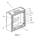
- a battery 36 is connected to the mechanism 34, as shown in figure 2. This can be a passive electronic solution for the firing mechanism 34, which thereby does not use power from the in-built battery 36.
- Such mechanisms are well known and will not be further described here.
- the spring system is arranged to exert a sufficient spring force so that the outer layers, i.e., the tier 18, mat 16 and the reinforced plate 14, are forced sufficiently against the outer wall 12, so that the mentioned layers do not move inwards and activate the electric circuit if a storage unit, composed of wall constructions according to the present invention, is exposed to normal impacts and strikes.
- the spring force must not be so large that the mentioned outer layers are not forced easily inwards to activate the electrical circuit at any attempts to break into the storage unit.
- the drill With attempts to drill through, or use an angle grinder on the wall construction, according to the present invention, the drill will push against the reinforced plate 14 and force this inwards so that the plate 14, the mat 16 and the foil 18 are moved towards the inner wall 22. This result in that the electric tier 18 (the foil) comprising the contact means close the electric circuit.
- the production of heat from the drill or angle grinder leads to the thermal mat 16 expanding and correspondingly pressing the electricity-conducting tier 18 inwards so that the electric circuit is activated.
- the reinforced plate 14 With attempts to remove the outer wall 12, or bend the outer wall outwards, the reinforced plate 14, because of the spring force, will also move outwards, or glide along the outer wall 12 such that, corresponding to that mentioned above, the contact means 24a,24b are closed or are broken, activating the electric circuit.
- the reinforced plate 14 is not secured to the outer wall, but is forced against the outer wall 12 due to the force from the springs 28a, 28b.
- the wall construction will, when composed of a number of corresponding wall constructions, provide a safe, transportable, or stationary storage box for storage of valuables, such as banknotes, ammunition, keys or the like.
Landscapes
- Finishing Walls (AREA)
- Distribution Board (AREA)
- Forms Removed On Construction Sites Or Auxiliary Members Thereof (AREA)
- Filling Or Discharging Of Gas Storage Vessels (AREA)
- Level Indicators Using A Float (AREA)
Claims (15)
- Wandkonstruktion (10), insbesondere für einen Aufbewahrungsbehälter für Wertgegenstände wie zum Beispiel Wertpapiere, umfassend eine äußere Wand (12) und eine innere Wand (22), zwischen welchen eine Anzahl von Schichten oder Lagen angeordnet ist, wobei eine der Lagen aus einem elektrisch leitenden Material besteht, und Kontaktmittel (24a, 24b) für die Aktivierung einer elektrischen Schaltung, dadurch gekennzeichnet, dass die Konstruktion (10) eine Zwischenmatte (16) zur thermischen Expansion und eine Kontaktmittel (24a, 24b) umfassende Zwischenschicht (20) und ein Federsystem (28a, 28b) umfasst, welche bei gegen- und mitwirkenden Einflüssen von einer Federkraft dazu angeordnet sind, sich entgegenzuwirken und sicherzustellen, dass die elektrische Schaltung aktiviert wird.
- Wandkonstruktion nach Anspruch 1, dadurch gekennzeichnet, dass die Zwischenmatte (16) zur thermischen Expansion und die Zwischenschicht (20) auf jeweils einer Seite der elektrisch leitenden Lage (18) angeordnet sind.
- Wandkonstruktion nach Anspruch 1, dadurch gekennzeichnet, dass die Konstruktion (10) darüber hinaus eine verstärkte Platte (14) beinhaltet, welche aus einem Material besteht, das wärmeleitend und widerstandsfähig gegenüber externen Beanspruchungen ist, und welche zwischen der thermischen Zwischenmatte (16) und der äußeren Wand (12) angeordnet ist.
- Wandkonstruktion nach Anspruch 3, dadurch gekennzeichnet, dass die Konstruktion (10) von innen nach außen aus einer inneren Wand (22), einer Schicht (20), welche Kontaktmittel (24a, 24b) und ein Federsystem (28a, 28b) umfasst, einer elektrisch leitenden Lage (18), einer Matte (16) zur thermischen Expansion, einer verstärkten Platte (14) und einer äußeren Wand (12) besteht.
- Wandkonstruktion nach Anspruch 4, dadurch gekennzeichnet, dass die Kontaktmittel (24a, 24b) eine Anzahl von gegen-überliegenden sich nach außen erstreckenden Kontaktarmen, Kontaktschienen oder Kontaktpuffern umfassen, welche jeweils an den äußeren Seiten der inneren Wand (22) und/oder der elektrisch leitenden Lage (18) oder der thermischen Matte (16) angeordnet sind.
- Wandkonstruktion nach Anspruch 4, dadurch gekennzeichnet, dass das Federsystem eine Anzahl von sich nach außen erstreckenden Bolzen (26a, 26b) umfasst, welche an den äußeren Seiten der inneren Wand (22) angeordnet sind, wobei sich die Bolzen (26a, 26b) bis zu oder in Richtung der äußeren Wand (12) erstrecken, wobei Spiralfedern (28a, 28b) auf den Bolzen (26a, 26b) angeordnet sind, welche dazu angeordnet sind, die elektrisch leitende Lage (18), die thermische Matte (16) und die verstärkte Platte (14) gegen die äußere Wand (12) zu zwingen.
- Wandkonstruktion nach einem der vorhergehenden Ansprüche, dadurch gekennzeichnet, dass die thermische Matte (16) eine graphitbasierte Mineralfaser aus einem stabilisierten Volumenexpansionsmaterial mit einer Dicke von zwischen 1,5 mm und 4,0 mm, vorzugsweise zwischen 1,8 mm und 3,0 mm, umfasst.
- Wandkonstruktion nach Anspruch 7, dadurch gekennzeichnet, dass die thermische Matte (16), wenn sie auf ungefähr 190°C erwärmt wird, ein Expansionsverhältnis von ungefähr 9:1 und bei ungefähr 400°C eine Expansionskraft von ungefähr 1,5 kg/cm2 aufweist.
- Wandkonstruktion nach einem der vorhergehenden Ansprüche, dadurch gekennzeichnet, dass die Wandkonstruktion (10) einen Zuführungseinlass (30) für Wertgegenstände einschließlich einer Banknotenzuführungsvorrichtung umfasst.
- Wandkonstruktion nach einem der vorhergehenden Ansprüche, dadurch gekennzeichnet, dass die Wandkonstruktion (10) eine Entnahmeöffnung (32) einschließlich einer verriegelbaren entfernbaren Platte umfasst.
- Verwendung einer Wandkonstruktion (10) nach Anspruch 1-10, wobei eine Anzahl der Wandkonstruktionen (10) kombiniert wird, um bei einer Aufbewahrungseinheit für Wertgegenstände, insbesondere für Wertpapiere, wie zum Beispiel Banknoten, Munition, Schlüssel oder Ähnlichem, eine Anzahl von Seiten zu Dilden.
- Verwendung nach Anspruch 11, wobei eine oder mehrere der Wandkonstruktionen (10) in der Aufbewahrungseinheit eine Zuführungsvorrichtung in einer Einlassöffnung in Form von zum Beispiel einer Banknotenzuführungsvorrichtung, durch welche Banknoten zugeführt werden, und eine Verriegelungsvorrichtung in einer Entnahmeöffnung in Form von zum Beispiel einem entfernbaren Verriegelungseinsatz, durch welchen Banknoten entnommen werden, umfasst.
- Verwendung nach Anspruch 11-12, wobei eine Anzahl von Wandkonstruktionen (10) eine transportable Aufbewahrungseinheit bildet, wobei Banknoten für einen sicheren Transport von einem Ort zu einem anderen sicheren Aufbewahrungsort vor dem Transport in die Einheit zugeführt werden.
- Verwendung nach Anspruch 11, wobei eine Anzahl von Wandkonstruktionen (10) eine stationäre Aufbewahrungseinheit für Wertgegenstände, wie zum Beispiel einen Safe oder Ähnliches bildet.
- Verwendung nach Anspruch 11, wobei eine Anzahl von Wandkonstruktionen (10) eine stationäre Aufbewahrungseinheit für Wertgegenstände bilden, und wobei die Aufbewahrungseinheit als ein integraler Teil eines Automaten, wie zum Beispiel eines Spielautomaten, eines Bezahlungsautomaten usw., oder im Zusammenhang mit Bezahlungseinrichtungen, wie zum Beispiel Kartenverkaufssystemen für Beförderungsmittel, Kino usw., angeordnet ist.
Applications Claiming Priority (3)
| Application Number | Priority Date | Filing Date | Title |
|---|---|---|---|
| NO20003390A NO312373B1 (no) | 2000-06-29 | 2000-06-29 | Veggkonstruksjon, s¶rlig for en oppbevaringsboks til verdisaker, samt anvendelse av en slik veggkonstruksjon somsidevegger i en oppbevaringsboks |
| NO20003390 | 2000-06-29 | ||
| PCT/NO2001/000278 WO2002006616A1 (en) | 2000-06-29 | 2001-06-29 | Wall construction for storage of valuables |
Publications (2)
| Publication Number | Publication Date |
|---|---|
| EP1301677A1 EP1301677A1 (de) | 2003-04-16 |
| EP1301677B1 true EP1301677B1 (de) | 2005-11-16 |
Family
ID=19911331
Family Applications (1)
| Application Number | Title | Priority Date | Filing Date |
|---|---|---|---|
| EP01963609A Expired - Lifetime EP1301677B1 (de) | 2000-06-29 | 2001-06-29 | Wandstruktur zur aufbewahrung von wertsachen |
Country Status (6)
| Country | Link |
|---|---|
| EP (1) | EP1301677B1 (de) |
| AT (1) | ATE310146T1 (de) |
| AU (1) | AU2001284541A1 (de) |
| DE (1) | DE60115046D1 (de) |
| NO (1) | NO312373B1 (de) |
| WO (1) | WO2002006616A1 (de) |
Families Citing this family (3)
| Publication number | Priority date | Publication date | Assignee | Title |
|---|---|---|---|---|
| DE10347027A1 (de) * | 2003-10-09 | 2005-05-25 | Eff-Eff Fritz Fuss Gmbh & Co. Kgaa | Verwendung eines intumeszierenden Materials und Vorrichtung mit einem derartigen Material |
| US8858801B2 (en) | 2009-02-24 | 2014-10-14 | Basf Se | Cu—Mo separation |
| CN104271247B (zh) | 2012-04-23 | 2017-10-27 | 巴斯夫欧洲公司 | 包括一步调理浆料的颗粒磁力分离 |
Family Cites Families (2)
| Publication number | Priority date | Publication date | Assignee | Title |
|---|---|---|---|---|
| AT315019B (de) * | 1971-02-23 | 1974-05-10 | Gao Ges Automation Org | Sicherheitsbehälter od.dgl. |
| GB9113437D0 (en) * | 1991-06-21 | 1991-08-07 | Gore W L & Ass Uk | Improvements in security enclosures |
-
2000
- 2000-06-29 NO NO20003390A patent/NO312373B1/no not_active IP Right Cessation
-
2001
- 2001-06-29 AU AU2001284541A patent/AU2001284541A1/en not_active Abandoned
- 2001-06-29 DE DE60115046T patent/DE60115046D1/de not_active Expired - Lifetime
- 2001-06-29 WO PCT/NO2001/000278 patent/WO2002006616A1/en not_active Ceased
- 2001-06-29 AT AT01963609T patent/ATE310146T1/de not_active IP Right Cessation
- 2001-06-29 EP EP01963609A patent/EP1301677B1/de not_active Expired - Lifetime
Also Published As
| Publication number | Publication date |
|---|---|
| DE60115046D1 (de) | 2005-12-22 |
| EP1301677A1 (de) | 2003-04-16 |
| ATE310146T1 (de) | 2005-12-15 |
| NO312373B1 (no) | 2002-04-29 |
| NO20003390L (no) | 2001-12-31 |
| WO2002006616A1 (en) | 2002-01-24 |
| AU2001284541A1 (en) | 2002-01-30 |
| NO20003390D0 (no) | 2000-06-29 |
Similar Documents
| Publication | Publication Date | Title |
|---|---|---|
| US8464648B2 (en) | Installation kit for equipping a case as a multifunctional, portable security system and case equipped with such an installation kit | |
| FI64436B (fi) | Foerfarande att aostadkomma saeker kontroll foervaring och transport av sedlar samt kassett foer utfoerande av foerfarandet | |
| GB1593041A (en) | Locking security container | |
| CN100564787C (zh) | 运送报警容器的方法和装置 | |
| US6553922B1 (en) | Safe for valuable documents | |
| WO2008038263A2 (en) | Key safe apparatus and method | |
| EP1301677A1 (de) | Wandstruktur zur bewahrung von wertsachen | |
| EP1961902A1 (de) | Gestell für den Transport von Wertgegenständen | |
| BR102013008514A2 (pt) | invólucro seguro | |
| JP4523283B2 (ja) | 容器に関する方法および装置 | |
| WO1990006414A1 (en) | Security box for installation in a safe | |
| CN2773278Y (zh) | 用于保险柜和运输箱的纸币及文件防盗抢装置 | |
| CN2937407Y (zh) | 多用智能箱 | |
| RU215326U1 (ru) | Контейнер для хранения и транспортировки ценных бумаг | |
| CN201045267Y (zh) | 保险箱 | |
| JPS63117707A (ja) | ポケット型保管ボックス | |
| CN2627594Y (zh) | 防盗收款箱 | |
| JP2001336323A (ja) | 駐車場精算機の保護枠体 | |
| CN2491570Y (zh) | 壁设防盗警戒网的标记型纸币保险箱柜 | |
| GB2326192A (en) | A container for carrying valuables protected by a dye dispersal system | |
| CN1477283A (zh) | 反抢劫银行运钞箱 | |
| PL185381B1 (pl) | Walizka do przewozu banknotow | |
| WO2002079599A1 (fr) | Securite pour billets de banque ou papier confidentiel proteges contre le vol et systeme de securite associe | |
| BRPI1005486A2 (pt) | dispositivo inibidor de roubos em caixas eletrÈnicos e assemelhados |
Legal Events
| Date | Code | Title | Description |
|---|---|---|---|
| PUAI | Public reference made under article 153(3) epc to a published international application that has entered the european phase |
Free format text: ORIGINAL CODE: 0009012 |
|
| 17P | Request for examination filed |
Effective date: 20030129 |
|
| AK | Designated contracting states |
Designated state(s): AT BE CH CY DE DK ES FI FR GB GR IE IT LI LU MC NL PT SE TR |
|
| AX | Request for extension of the european patent |
Extension state: AL LT LV MK RO SI |
|
| GRAP | Despatch of communication of intention to grant a patent |
Free format text: ORIGINAL CODE: EPIDOSNIGR1 |
|
| GRAS | Grant fee paid |
Free format text: ORIGINAL CODE: EPIDOSNIGR3 |
|
| GRAA | (expected) grant |
Free format text: ORIGINAL CODE: 0009210 |
|
| AK | Designated contracting states |
Kind code of ref document: B1 Designated state(s): AT BE CH CY DE DK ES FI FR GB GR IE IT LI LU MC NL PT SE TR |
|
| PG25 | Lapsed in a contracting state [announced via postgrant information from national office to epo] |
Ref country code: AT Free format text: LAPSE BECAUSE OF FAILURE TO SUBMIT A TRANSLATION OF THE DESCRIPTION OR TO PAY THE FEE WITHIN THE PRESCRIBED TIME-LIMIT Effective date: 20051116 Ref country code: IT Free format text: LAPSE BECAUSE OF FAILURE TO SUBMIT A TRANSLATION OF THE DESCRIPTION OR TO PAY THE FEE WITHIN THE PRESCRIBED TIME-LIMIT;WARNING: LAPSES OF ITALIAN PATENTS WITH EFFECTIVE DATE BEFORE 2007 MAY HAVE OCCURRED AT ANY TIME BEFORE 2007. THE CORRECT EFFECTIVE DATE MAY BE DIFFERENT FROM THE ONE RECORDED. Effective date: 20051116 Ref country code: NL Free format text: LAPSE BECAUSE OF FAILURE TO SUBMIT A TRANSLATION OF THE DESCRIPTION OR TO PAY THE FEE WITHIN THE PRESCRIBED TIME-LIMIT Effective date: 20051116 Ref country code: FI Free format text: LAPSE BECAUSE OF FAILURE TO SUBMIT A TRANSLATION OF THE DESCRIPTION OR TO PAY THE FEE WITHIN THE PRESCRIBED TIME-LIMIT Effective date: 20051116 Ref country code: LI Free format text: LAPSE BECAUSE OF FAILURE TO SUBMIT A TRANSLATION OF THE DESCRIPTION OR TO PAY THE FEE WITHIN THE PRESCRIBED TIME-LIMIT Effective date: 20051116 Ref country code: CH Free format text: LAPSE BECAUSE OF FAILURE TO SUBMIT A TRANSLATION OF THE DESCRIPTION OR TO PAY THE FEE WITHIN THE PRESCRIBED TIME-LIMIT Effective date: 20051116 Ref country code: BE Free format text: LAPSE BECAUSE OF FAILURE TO SUBMIT A TRANSLATION OF THE DESCRIPTION OR TO PAY THE FEE WITHIN THE PRESCRIBED TIME-LIMIT Effective date: 20051116 |
|
| REG | Reference to a national code |
Ref country code: GB Ref legal event code: FG4D |
|
| REG | Reference to a national code |
Ref country code: CH Ref legal event code: EP |
|
| REG | Reference to a national code |
Ref country code: IE Ref legal event code: FG4D |
|
| REF | Corresponds to: |
Ref document number: 60115046 Country of ref document: DE Date of ref document: 20051222 Kind code of ref document: P |
|
| PG25 | Lapsed in a contracting state [announced via postgrant information from national office to epo] |
Ref country code: DK Free format text: LAPSE BECAUSE OF FAILURE TO SUBMIT A TRANSLATION OF THE DESCRIPTION OR TO PAY THE FEE WITHIN THE PRESCRIBED TIME-LIMIT Effective date: 20060216 Ref country code: GR Free format text: LAPSE BECAUSE OF FAILURE TO SUBMIT A TRANSLATION OF THE DESCRIPTION OR TO PAY THE FEE WITHIN THE PRESCRIBED TIME-LIMIT Effective date: 20060216 |
|
| PG25 | Lapsed in a contracting state [announced via postgrant information from national office to epo] |
Ref country code: DE Free format text: LAPSE BECAUSE OF FAILURE TO SUBMIT A TRANSLATION OF THE DESCRIPTION OR TO PAY THE FEE WITHIN THE PRESCRIBED TIME-LIMIT Effective date: 20060217 |
|
| PG25 | Lapsed in a contracting state [announced via postgrant information from national office to epo] |
Ref country code: ES Free format text: LAPSE BECAUSE OF FAILURE TO SUBMIT A TRANSLATION OF THE DESCRIPTION OR TO PAY THE FEE WITHIN THE PRESCRIBED TIME-LIMIT Effective date: 20060227 |
|
| REG | Reference to a national code |
Ref country code: SE Ref legal event code: TRGR |
|
| PG25 | Lapsed in a contracting state [announced via postgrant information from national office to epo] |
Ref country code: PT Free format text: LAPSE BECAUSE OF FAILURE TO SUBMIT A TRANSLATION OF THE DESCRIPTION OR TO PAY THE FEE WITHIN THE PRESCRIBED TIME-LIMIT Effective date: 20060417 |
|
| NLV1 | Nl: lapsed or annulled due to failure to fulfill the requirements of art. 29p and 29m of the patents act | ||
| REG | Reference to a national code |
Ref country code: CH Ref legal event code: PL |
|
| PG25 | Lapsed in a contracting state [announced via postgrant information from national office to epo] |
Ref country code: GB Free format text: LAPSE BECAUSE OF NON-PAYMENT OF DUE FEES Effective date: 20060629 Ref country code: IE Free format text: LAPSE BECAUSE OF NON-PAYMENT OF DUE FEES Effective date: 20060629 |
|
| PG25 | Lapsed in a contracting state [announced via postgrant information from national office to epo] |
Ref country code: MC Free format text: LAPSE BECAUSE OF NON-PAYMENT OF DUE FEES Effective date: 20060630 |
|
| PLBE | No opposition filed within time limit |
Free format text: ORIGINAL CODE: 0009261 |
|
| STAA | Information on the status of an ep patent application or granted ep patent |
Free format text: STATUS: NO OPPOSITION FILED WITHIN TIME LIMIT |
|
| 26N | No opposition filed |
Effective date: 20060817 |
|
| EN | Fr: translation not filed | ||
| GBPC | Gb: european patent ceased through non-payment of renewal fee |
Effective date: 20060629 |
|
| REG | Reference to a national code |
Ref country code: IE Ref legal event code: MM4A |
|
| PG25 | Lapsed in a contracting state [announced via postgrant information from national office to epo] |
Ref country code: FR Free format text: LAPSE BECAUSE OF FAILURE TO SUBMIT A TRANSLATION OF THE DESCRIPTION OR TO PAY THE FEE WITHIN THE PRESCRIBED TIME-LIMIT Effective date: 20070105 |
|
| PG25 | Lapsed in a contracting state [announced via postgrant information from national office to epo] |
Ref country code: LU Free format text: LAPSE BECAUSE OF NON-PAYMENT OF DUE FEES Effective date: 20060629 Ref country code: TR Free format text: LAPSE BECAUSE OF FAILURE TO SUBMIT A TRANSLATION OF THE DESCRIPTION OR TO PAY THE FEE WITHIN THE PRESCRIBED TIME-LIMIT Effective date: 20051116 |
|
| PG25 | Lapsed in a contracting state [announced via postgrant information from national office to epo] |
Ref country code: CY Free format text: LAPSE BECAUSE OF FAILURE TO SUBMIT A TRANSLATION OF THE DESCRIPTION OR TO PAY THE FEE WITHIN THE PRESCRIBED TIME-LIMIT Effective date: 20051116 Ref country code: FR Free format text: LAPSE BECAUSE OF FAILURE TO SUBMIT A TRANSLATION OF THE DESCRIPTION OR TO PAY THE FEE WITHIN THE PRESCRIBED TIME-LIMIT Effective date: 20051116 |
|
| PGFP | Annual fee paid to national office [announced via postgrant information from national office to epo] |
Ref country code: SE Payment date: 20091222 Year of fee payment: 9 |
|
| EUG | Se: european patent has lapsed | ||
| PG25 | Lapsed in a contracting state [announced via postgrant information from national office to epo] |
Ref country code: SE Free format text: LAPSE BECAUSE OF NON-PAYMENT OF DUE FEES Effective date: 20100630 |