EP1301809B1 - 3d-bohrlochradarantenne - Google Patents
3d-bohrlochradarantenne Download PDFInfo
- Publication number
- EP1301809B1 EP1301809B1 EP01950107A EP01950107A EP1301809B1 EP 1301809 B1 EP1301809 B1 EP 1301809B1 EP 01950107 A EP01950107 A EP 01950107A EP 01950107 A EP01950107 A EP 01950107A EP 1301809 B1 EP1301809 B1 EP 1301809B1
- Authority
- EP
- European Patent Office
- Prior art keywords
- housing
- borehole radar
- tool according
- reflector
- antenna
- Prior art date
- Legal status (The legal status is an assumption and is not a legal conclusion. Google has not performed a legal analysis and makes no representation as to the accuracy of the status listed.)
- Expired - Lifetime
Links
- 230000005670 electromagnetic radiation Effects 0.000 claims description 16
- XLYOFNOQVPJJNP-UHFFFAOYSA-N water Substances O XLYOFNOQVPJJNP-UHFFFAOYSA-N 0.000 claims description 7
- 230000007704 transition Effects 0.000 claims description 3
- 238000000034 method Methods 0.000 abstract 4
- 238000004590 computer program Methods 0.000 abstract 1
- 230000005672 electromagnetic field Effects 0.000 abstract 1
- 230000006698 induction Effects 0.000 abstract 1
- 230000000149 penetrating effect Effects 0.000 description 9
- 238000005259 measurement Methods 0.000 description 8
- 230000005855 radiation Effects 0.000 description 8
- 238000009434 installation Methods 0.000 description 6
- 239000004576 sand Substances 0.000 description 5
- 230000035945 sensitivity Effects 0.000 description 5
- 230000000694 effects Effects 0.000 description 4
- 239000003673 groundwater Substances 0.000 description 3
- 239000000203 mixture Substances 0.000 description 3
- 238000007789 sealing Methods 0.000 description 3
- 230000002411 adverse Effects 0.000 description 2
- JRPBQTZRNDNNOP-UHFFFAOYSA-N barium titanate Chemical compound [Ba+2].[Ba+2].[O-][Ti]([O-])([O-])[O-] JRPBQTZRNDNNOP-UHFFFAOYSA-N 0.000 description 2
- 229910002113 barium titanate Inorganic materials 0.000 description 2
- 230000008901 benefit Effects 0.000 description 2
- 230000015572 biosynthetic process Effects 0.000 description 2
- 230000008859 change Effects 0.000 description 2
- 230000008878 coupling Effects 0.000 description 2
- 238000010168 coupling process Methods 0.000 description 2
- 238000005859 coupling reaction Methods 0.000 description 2
- 239000003989 dielectric material Substances 0.000 description 2
- 239000002689 soil Substances 0.000 description 2
- 239000000725 suspension Substances 0.000 description 2
- 238000005452 bending Methods 0.000 description 1
- 239000002802 bituminous coal Substances 0.000 description 1
- 239000004927 clay Substances 0.000 description 1
- 230000007423 decrease Effects 0.000 description 1
- 238000011156 evaluation Methods 0.000 description 1
- 238000000605 extraction Methods 0.000 description 1
- 230000006872 improvement Effects 0.000 description 1
- 229910052500 inorganic mineral Inorganic materials 0.000 description 1
- 239000012774 insulation material Substances 0.000 description 1
- 239000000463 material Substances 0.000 description 1
- 229910052751 metal Inorganic materials 0.000 description 1
- 239000002184 metal Substances 0.000 description 1
- 239000011707 mineral Substances 0.000 description 1
- 239000012811 non-conductive material Substances 0.000 description 1
- 230000035515 penetration Effects 0.000 description 1
- 239000000843 powder Substances 0.000 description 1
- 238000004904 shortening Methods 0.000 description 1
Images
Classifications
-
- G—PHYSICS
- G01—MEASURING; TESTING
- G01V—GEOPHYSICS; GRAVITATIONAL MEASUREMENTS; DETECTING MASSES OR OBJECTS; TAGS
- G01V3/00—Electric or magnetic prospecting or detecting; Measuring magnetic field characteristics of the earth, e.g. declination, deviation
- G01V3/18—Electric or magnetic prospecting or detecting; Measuring magnetic field characteristics of the earth, e.g. declination, deviation specially adapted for well-logging
- G01V3/30—Electric or magnetic prospecting or detecting; Measuring magnetic field characteristics of the earth, e.g. declination, deviation specially adapted for well-logging operating with electromagnetic waves
Definitions
- the present invention relates to a borehole radar tool according to the preamble of claim 1.
- a borehole radar tool of this type is described in WO-A-89/03053.
- This publication describes a radar instrument for use in a borehole for locating fractures in a geological formation, comprising directionally sensitive transmitting and receiving antennae.
- Emitting means generate a pulsed radar signal with an output in the frequency range of between 30 and 300 MHz.
- This signal is radiated via a reflector, in particular a reflector consisting of two electroconductive plates arranged in the shape of a V.
- a receiving antenna provided with a similar reflector, is used to intercept the radar signal reflected by the formation.
- the space through which the radiation propagates within the housing is filled with a barium titanate powder/air mixture, whose dielectric constant matches that of the surroundings and in particular has a value of about 80.
- GB-A-2100544 discloses a short pulse radar drill guidance system with a radar tool that comprises a casing housing a source of electro-magnetic pulses, a transmitting means connected to that source, receiving means, directive antenna means for the transmitting and receiving means and control circuit means.
- the configuration of these components within the tool casing is designed to minimise the effects of electromagnetic coupling between transmitting and receiving antennas and thus misleading readings consequent thereon.
- the present invention provides a borehole radar tool according to claim 1.
- the first variable is the ratio between the emitted power in the target direction and the emitted power in the other direction(s). This ratio should be as large as possible.
- the second variable is the total power emitted in the target direction. Obviously, this should be as large as possible. This is desirable to achieve the highest possible penetrative power. Thus a good image of the subsurface can be obtained with as small a number as possible of expensive boreholes.
- the reflector should have a certain surface area.
- optimal dimensions exist for the reflector, which predominantly depend on the constrained dimensions of the housing.
- the first aspect of the invention provides, in addition, for the distance from the transmitting and/or the receiving antenna to the reflective surface to be as large as possible. This is achieved by means of a borehole radar tool according to the first aspect of the invention.
- distance in this context refers to the mean distance between the reflective surface and the transmitting or receiving antenna.
- the term "near the wall of the housing” in this context means that the relevant section of the reflector, or the centre of the transmitting and/or the receiving antenna, respectively, is located at a distance from the inner wall of the housing which is at most a quarter of the inside diameter of the housing.
- the distance between the inner wall of the housing and the relevant section of the reflector, or the transmitting and/or the receiving antenna, respectively is at most 2 cm, advantageously less than 1 cm.
- the distance can alternatively be greater than 2 cm.
- the housing is fashioned as a cylinder from a nonconductive material, for example plastic, part of the cylinder being formed by the reflector section which is fabricated from metal, for example.
- At least one of the reflectors comprises a thin plate.
- a narrow space exists between the reflector and the housing, said space accommodating, for example, the cabling to the transmitting and/or receiving antenna. It is important for said cabling to be screened against electromagnetic radiation present in the space between the reflective surface and that section of the wall of the housing which is situated opposite thereto.
- the reflector can serve as such a screen.
- the shape of the reflector, and in particular of the reflective surface, is not subject to any particular constraint. Suitable, for example, are two straight plates touching one another at one end, each end of both plates being situated near the wall of the housing. This affords a V-shaped reflector.
- At least one reflective surface is a substantially smoothly curved surface which, as seen in the axial direction of the housing, at least substantially forms part of a conic. Giving the reflective surface such a shape makes it possible to ensure that the reflective surface at least largely follows the shape of the wall of the housing, thus making the mean distance from the reflector to the transmitting and/or receiving antenna as large as possible.
- substantially smoothly curved in this context means that it is acceptable for the reflective surface to exhibit deviations in its shape whose dimensions are much smaller than the wavelength used, in particular at most 1/10 of the wavelength of the electromagnetic radiation. Owing to the wave properties of the electromagnetic radiation, the reflective surface will then still appear to be smoothly curved. Examples of such deviations in shape are holes for wiring, or bending edges in a faceted reflector.
- the conic is preferably chosen to be as advantageous as possible.
- the conic is a circle having a radius which is substantially equal to half the inside diameter of the housing. In this way, it is ensured that the mean distance between the reflective surface and the transmitting and/or receiving antenna is at its maximum. If the reflective surface is formed by the inner wall of the housing, the radius of the circle is equal to half the inside diameter of the housing. If the reflector is a thin plate near the inner wall of the housing, the radius of the circle is equal to half the inside diameter of the housing minus the thickness of the plate, possibly reduced by the distance between plate and inner wall of the housing. In particular, the last-mentioned distance is less than 2 cm, advantageously less than 1 cm.
- the angle formed by at least one of the reflectors is between 45° and 180°. If said angle is between these two limits, a satisfactory emission characteristic is obtained owing to the reflective surface being large enough without too much radiation being lost via reflection of the emitted or intercepted radiation in a direction other than the desired one.
- the angle formed by at least one of the reflectors is between 145° and 155°. At these angles, an even better emission characteristic and consequently a better directional sensitivity is obtained.
- the conic is a parabola.
- the focal length of the parabola is between 0.5 and 0.75 times the inside diameter of the housing.
- the centre of the transmitting and/or receiving antenna is in the focal point of the parabola, but it was found that it is more important for the distance between reflective surface and transmitting and/or receiving antenna to be as large as possible.
- the space between the reflective surfaces and that section of the wall of the housing which in each case is situated opposite thereto is filled with a dielectric.
- the function of the dielectric is, on the one hand, to shorten the wavelength of the electromagnetic radiation in the region between the antennae and the reflective surface. This results in an improvement of the collimating characteristics of the reflective surface.
- the dielectric constant of the dielectric is in principle chosen to be as large as possible.
- the value of the dielectric constant of the dielectric at the transition towards the surrounding subsurface must match the value of the dielectric constant of that subsurface.
- the dielectric constant of, for example, the Dutch subsurface varies between ⁇ 5 (dry sand) and ⁇ 40 (wet sand, clay), and ⁇ 80 for water (e.g. groundwater).
- the smaller the difference in the dielectric constant between the subsurface and the dielectric the larger the proportion of the generated electromagnetic radiation which actually penetrates the subsurface. This is desirable in order to be able to sample as large a proportion of this subsurface as possible by means of one measurement. With high penetrative power, measurements can extend to large distances, thereby requiring relatively few expensive boreholes.
- that fraction of said space which adjoins the wall of the housing can be filled with a suitable dielectric.
- the space between the reflective surfaces and that part of the wall of the housing which in each case is situated opposite thereto can be completely filled with one dielectric.
- the dielectric in the space between the reflective surfaces and that section of the wall of the housing which in each case is located opposite thereto has a dielectric constant of between 20 and 100, and more preferably between 60 and 100 and most preferably of about 80. At these values for the dielectric constant, a satisfactory compromise is achieved between suitable wavelength shortening for good collimating characteristics and a large proportion of radiation penetrating into the subsurface.
- the dielectric substantially comprises water.
- water is particularly suitable, but e.g. barium titanate/air mixtures, as disclosed in WO-A-89/03053 will likewise be quite satisfactory.
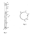
- 1 indicates a borehole radar tool according to the first aspect of the invention.
- This comprises a housing 2 which, at its top and bottom, is sealed with the aid of sealing components 3.
- the sealing components 3 are provided, for example, with wheels 13 to guide the borehole radar installation within a borehole.
- the top sealing component 3 is provided with a hoisting eye 14, by means of which the borehole radar installation 1 can be moved upwards or downwards.
- 4 indicates a part not elaborated in any detail, which may include, for example, control electronics, as well as means by which antenna components are rotated within the housing, and gyroscopes for determining the orientation of the antenna components.
- the borehole radar tool can perform a measurement in the desired direction.
- measurements can be carried out, for example, as follows.
- the borehole radar tool 1 is introduced into a borehole, being connected to control means which allow it to be controlled from ground level.
- the orientation of the borehole radar tool 1 with respect to the earth is determined.
- a measuring cycle then commences by emitting electromagnetic radiation and intercepting the reflected radiation and recording it in the form of a signal.
- the transmitting antenna assembly 6 and the receiving antenna assembly 7 being rotated by a small angle, e.g. 2° or 3°, and a next measurement then being carried out.
- These steps are repeated until a measurement has been carried out in all the desired directions.
- the borehole radar installation 1 is moved to a different depth, whereupon all the abovementioned steps are repeated.
- the borehole radar tool can be equipped so as to be capable of autonomous measurement and movement. This will then require, for example, an energy source such as a battery, propulsion means such as an electrically operable cable reel, and built-in control means such as a control and measuring program to be provided.
- an energy source such as a battery
- propulsion means such as an electrically operable cable reel
- built-in control means such as a control and measuring program
- the profile consists of a number of transitions in the subsurface where the electromagnetic characteristics change. This may indicate a fracture in the subsurface, a change in composition (e.g. bituminous coal, oil), but also the presence of an object such as an unexploded bomb. Evaluation and interpretation of the data can be carried out subsequently.
- composition e.g. bituminous coal, oil
- the borehole radar tool 1 can be used in a variety of fields: the exploration of the environment of boreholes for the purpose of, for example, digging activities or extraction of minerals, tracing of objects present in the subsurface such as unexploded bombs or shells etc.
- the borehole radar installation can be adapted according to the desired application and the subsurface in which the measurements are to be carried out.
- a lower frequency generally provides a larger penetrative power but lower resolution.
- the penetrative power also depends on the subsurface characteristics. If the subsurface is highly penetrable, for example sand above the groundwater table, it is possible to opt for an increase in frequency in order thus to increase the resolution. Again, however, the fact is that given the cost of boreholes, the emphasis in the first instance is on penetrative power. Only in special cases, therefore, will the frequency be increased. Consequently, the frequency used is preferably between 20 and 200 MHz.
- dielectric other than water can be chosen if appropriate.
- the dielectric constant of a sand soil above the groundwater table (dry sand) is considerably lower than that of water-saturated sand.
- a lower value must therefore be chosen for the dielectric constant of the filling dielectric in order to retain sufficient emitted power. This does result in an increase in the wavelength of the electromagnetic radiation within the housing, adversely affecting the collimating characteristics of the reflector. This can be resolved, for example, by using a higher frequency. Whilst the penetrative power of electromagnetic radiation generally decreases with increasing frequency, this effect is compensated for by the better penetration characteristics in sandy soils. Another option is to adjust the shape and/or dimensions of the reflector.
- Figure 2 depicts a schematic cross section of an antenna component. Lying against the housing 2 is a dipole antenna 8. Situated diametrically opposite thereto is a reflector 10 in the form of an almost semicircular electroconductive plate. The space between the reflector 10 and the antenna 8 is filled with water.
- the antenna 8 here is not located in the focal point of the reflector 10. This means that no substantially parallel radiation can be obtained. It should be noted in this context that in the case of cylindrical reflectors, the centre is regarded as the focal point, although strictly speaking this applies only to a small portion of the reflector and even then only by approximation. In most borehole radar installations, however, the wavelength used is of the same order of magnitude as the diameter of the borehole radar installation or as the dimension of the reflector. As a result of the distance between antenna 8 and reflector 10 being larger than the distance in the case where the transmitter would be located in the focal point of reflector 10, the adverse effects of the off-focus position are more than compensated for by the increased distance.
- the reflectors of the transmitting and receiving section, respectively are not earthed. This minimizes any problems, especially with the receiving section, given the minimal coupling with the transmitting section.
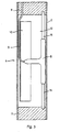
- FIG. 3 depicts a schematic cross section of the transmitting antenna component of a borehole radar tool 1.
- the dipole antenna 8 (almost) lies against the wall of the housing 2.
- the antenna 8 is held in the correct position by two suspension brackets 15.
- the antenna 8 can be driven via cabling 9.
- Said cabling 9 is located in the space between the reflector 10, located diametrically opposite the transmitting antenna 8, and the wall of the housing 2.
- 11 indicates insulation material which serves to absorb electromagnetic radiation radiated directly from the transmitting antenna towards the receiving antenna. At the same time, the material 11 serves to secure the suspension brackets 15.
- the space 12 between the reflector 10 and the transmitting antenna 8 is filled with a dielectric material, in this case water.
- the reflector 10 is not placed entirely against the wall of the housing 2. This provides the advantage, however, that space is provided for the cabling 9 and other components which are sensitive to interference caused by the emitted electromagnetic radiation. Nevertheless, it remains important for the distance between the transmitting antenna 8 and the reflector 10 to remain as large as possible. The same requirement equally applies to the receiving antenna.
Landscapes
- Physics & Mathematics (AREA)
- Life Sciences & Earth Sciences (AREA)
- Electromagnetism (AREA)
- Engineering & Computer Science (AREA)
- Environmental & Geological Engineering (AREA)
- Geology (AREA)
- Remote Sensing (AREA)
- General Life Sciences & Earth Sciences (AREA)
- General Physics & Mathematics (AREA)
- Geophysics (AREA)
- Geophysics And Detection Of Objects (AREA)
- Radar Systems Or Details Thereof (AREA)
Claims (10)
- Bohrloch-Radargerät zum richtungsempfindlichen Lokalisieren von Übergängen in dem das Bohrloch-Radargerät bei Benutzung umgebenden Untergrund, mit einer Erzeugereinrichtung zum Erzeugen der elektromagnetischen Strahlung, einer Signalbearbeitungseinrichtung zum Bearbeiten der empfangenen elektromagnetischen Strahlung und einem Gehäuse (2) mit einer im Wesentlichen zylinderförmigen Wand und einer Mittelachse, welches wenigstens aufnimmt:- eine Sendeantennen-Einheit (6) zum Senden der durch die Erzeugereinrichtung erzeugten elektromagnetischen Strahlung, mit einer Sendeantenne und einem elektrisch leitfähigen Reflektor (10); und- eine Empfangsantennen-Einheit (7) zum Empfangen der durch den umgebenden Untergrund reflektierten elektromagnetischen Strahlung, mit einer Empfangsantenne und einem elektrisch leitenden Reflektor (10),wobei sich sowohl die Sendeantenne als auch die Empfangsantenne parallel zur Achse des Gehäuses (2) erstrecken und beide eine Dipolantenne (8) umfassen, wobei jeder Reflektor (10) eine Reflektionsfläche aufweist, welche sich neben und parallel zur jeweiligen Dipolantenne (8) in einem Abstand von dieser erstreckt, und der Raum (12) zwischen jeder Reflektionsfläche und dem Abschnitt des Gehäuses (2), welcher in jedem Falle gegenüber derselben liegt, mit einem Medium gefüllt ist, das eine Dielektrizitätskonstante von wenigstens 10 gefüllt ist, wobei sich die Sendeantenne und die Empfangsantenne nahe der Wand des Gehäuses (2) erstrecken, derart, dass wenigstens der Abschnitt des Reflektors (10), welcher diametral gegenüber der Sendeantenne bzw. der Empfangsantenne angeordnet ist, sich ebenfalls nahe der Wand des Gehäuses (2) erstreckt, dadurch gekennzeichnet, dass wenigstens einer der Reflektoren (10) ein Teil der Wand des Gehäuses (2) bildet und dass die elektromagnetische Strahlung eine Frequenz von zwischen 10 MHz und 200 MHz hat.
- Bohrloch-Radargerät nach Anspruch 1, dadurch gekennzeichnet, dass wenigstens einer der Reflektoren (10) eine dünne Platte umfasst.
- Bohrloch-Radargerät gemäß einem oder mehreren der vorstehenden Ansprüche, dadurch gekennzeichnet, dass wenigstens eine Reflektionsfläche eine im Wesentlichen glatt gekrümmte Oberfläche ist, welche aus Sicht in der axialen Richtung des Gehäuses (2) wenigstens im Wesentlichen ein Teil eines Kegelschnittes bildet.
- Bohrloch-Radargerät nach Anspruch 3, dadurch gekennzeichnet, dass der Kegelschnitt ein Kreis mit einem Radius ist, welcher im Wesentlichen gleich der Hälfte des Innendurchmessers des Gehäuses (2) beträgt.
- Bohrloch-Radargerät nach Anspruch 4, dadurch gekennzeichnet, dass der durch wenigstens einen der Reflektoren (10) gebildete Winkel zwischen 45° und 180° beträgt.
- Bohrloch-Radargerät nach Anspruch 4, dadurch gekennzeichnet, dass der durch wenigstens einen der Reflektoren (10) gebildete Winkel zwischen 145° und 155° beträgt.
- Bohrloch-Radargerät nach Anspruch 3, dadurch gekennzeichnet, dass der Kegelschnitt eine Parabel ist.
- Bohrloch-Radargerät nach einem oder mehreren der vorstehenden Ansprüche, dadurch gekennzeichnet, dass der Nichtleiter in dem Raum (12) zwischen den Reflektionsflächen und dem Abschnitt der Wand des Gehäuses (2), welche in jedem Falle diesen gegenüber liegt, eine Dielektrizitätskonstante zwischen 20 und 100 hat.
- Bohrloch-Radargerät nach einem oder mehreren der vorstehenden Ansprüche, dadurch gekennzeichnet, dass der Nichtleiter in dem Raum (12) zwischen den Reflektionsflächen und dem Abschnitt der Wand des Gehäuses (2), welcher in jedem Falle diesen gegenüber liegt, eine Dielektrizitätskonstante von zwischen 60 und 100 hat.
- Bohrloch-Radargerät nach Anspruch 8 oder 9, dadurch gekennzeichnet, dass der Nichtleiter im Wesentlichen Wasser umfasst.
Applications Claiming Priority (7)
| Application Number | Priority Date | Filing Date | Title |
|---|---|---|---|
| NL1015651A NL1015651C2 (nl) | 2000-07-07 | 2000-07-07 | 3D-boorgatradarantenne. |
| NL1015651 | 2000-07-07 | ||
| NL1016200 | 2000-09-15 | ||
| NL1016200A NL1016200C2 (nl) | 2000-09-15 | 2000-09-15 | Bepaling van elektromagnetische contrastinformatie van een object. |
| NL1016363 | 2000-10-09 | ||
| NL1016363A NL1016363C2 (nl) | 2000-10-09 | 2000-10-09 | Werkwijze voor bodemonderzoek, en inrichting voor het uitvoeren van de werkwijze. |
| PCT/NL2001/000509 WO2002004987A2 (en) | 2000-07-07 | 2001-07-05 | 3d borehole radar antenna and algorithm, method and apparatus for subsurface surveys |
Publications (2)
| Publication Number | Publication Date |
|---|---|
| EP1301809A2 EP1301809A2 (de) | 2003-04-16 |
| EP1301809B1 true EP1301809B1 (de) | 2006-11-29 |
Family
ID=27351235
Family Applications (1)
| Application Number | Title | Priority Date | Filing Date |
|---|---|---|---|
| EP01950107A Expired - Lifetime EP1301809B1 (de) | 2000-07-07 | 2001-07-05 | 3d-bohrlochradarantenne |
Country Status (8)
| Country | Link |
|---|---|
| US (1) | US6712140B2 (de) |
| EP (1) | EP1301809B1 (de) |
| JP (1) | JP4768203B2 (de) |
| AT (1) | ATE347114T1 (de) |
| AU (2) | AU2001271138B2 (de) |
| CA (1) | CA2415651C (de) |
| DE (1) | DE60124919T2 (de) |
| WO (1) | WO2002004987A2 (de) |
Families Citing this family (20)
| Publication number | Priority date | Publication date | Assignee | Title |
|---|---|---|---|---|
| US6541979B2 (en) * | 2000-12-19 | 2003-04-01 | Schlumberger Technology Corporation | Multi-coil electromagnetic focusing methods and apparatus to reduce borehole eccentricity effects |
| US6924646B2 (en) * | 2002-12-31 | 2005-08-02 | Schlumberger Technology Corporation | System and method for locating a fracture in an earth formation |
| US8593147B2 (en) | 2006-08-08 | 2013-11-26 | Halliburton Energy Services, Inc. | Resistivity logging with reduced dip artifacts |
| EP2066866B1 (de) | 2006-12-15 | 2018-09-12 | Halliburton Energy Services, Inc. | Antennenkupplungskomponentenmesswerkzeug mit rotierender antennenkonfiguration |
| US8744817B2 (en) | 2007-12-21 | 2014-06-03 | Schlumberger Technology Corporation | Method for upscaling a reservoir model using deep reading measurements |
| US8738341B2 (en) * | 2007-12-21 | 2014-05-27 | Schlumberger Technology Corporation | Method for reservoir characterization and monitoring including deep reading quad combo measurements |
| US9732559B2 (en) * | 2008-01-18 | 2017-08-15 | Halliburton Energy Services, Inc. | EM-guided drilling relative to an existing borehole |
| IT1391797B1 (it) * | 2008-11-21 | 2012-01-27 | Eni Spa | Metodo e sistema di rilevamento della geometria di fratture sotterranee |
| US8957683B2 (en) | 2008-11-24 | 2015-02-17 | Halliburton Energy Services, Inc. | High frequency dielectric measurement tool |
| JP5568237B2 (ja) * | 2009-01-13 | 2014-08-06 | 松永ジオサーベイ株式会社 | 三次元位置推定システム、及び、ダイポールアレイアンテナ |
| CA2800148C (en) | 2010-06-29 | 2015-06-23 | Halliburton Energy Services, Inc. | Method and apparatus for sensing elongated subterranean anomalies |
| CN103477247B (zh) | 2011-04-18 | 2017-08-22 | 哈利伯顿能源服务公司 | 多分量钻井雷达系统和方法 |
| BR112014030170A2 (pt) | 2012-06-25 | 2017-06-27 | Halliburton Energy Services Inc | método e sistema de perfilagem eletromagnética |
| RU2558745C1 (ru) * | 2014-05-22 | 2015-08-10 | Федеральное государственное бюджетное учреждение науки Институт радиотехники и электроники им. В.А. Котельникова Российской академии наук | Способ дистанционного обнаружения неоднородностей в оптически непрозрачных средах |
| US10167709B2 (en) * | 2014-06-09 | 2019-01-01 | Turboshale, Inc. | Subsurface multiple antenna radiation technology (SMART) |
| CN111025290A (zh) * | 2019-12-31 | 2020-04-17 | 电子科技大学 | 钻孔雷达高效率成像前融合方法及系统 |
| GB2601116B (en) * | 2020-11-13 | 2023-02-15 | Hypertunnel Ip Ltd | A device and method for imaging underground features from a borehole |
| CN112578375B (zh) * | 2020-12-13 | 2023-12-15 | 中国电波传播研究所(中国电子科技集团公司第二十二研究所) | 一种手持式复合探测器探头及其制备方法 |
| CN115436717B (zh) * | 2022-09-16 | 2024-09-03 | 中国工程物理研究院应用电子学研究所 | 一种线缆护套高频脉冲电磁屏蔽效能测试装置 |
| CN118208227B (zh) * | 2024-05-16 | 2024-07-23 | 山东九商定向钻探有限公司 | 一种基于电磁波的定向钻探测量分析方法 |
Family Cites Families (24)
| Publication number | Priority date | Publication date | Assignee | Title |
|---|---|---|---|---|
| US4045724A (en) * | 1976-04-06 | 1977-08-30 | The United States Of America As Represented By The United States Energy Research And Development Administration | Electromagnetic wave method for mapping subterranean earth formations |
| GB1532710A (en) | 1976-06-21 | 1978-11-22 | Univ Ohio | Underground object detection |
| US4297699A (en) * | 1979-10-24 | 1981-10-27 | Ensco, Inc. | Radar drill guidance system |
| US4430653A (en) | 1979-11-02 | 1984-02-07 | Conoco Inc. | Earth probing radar system |
| GB2100544B (en) * | 1981-06-16 | 1985-11-20 | Ensco Inc | Radar drill guidance system |
| DE3308559C2 (de) * | 1983-03-08 | 1985-03-07 | Prakla-Seismos Gmbh, 3000 Hannover | Bohrloch-Meßeinrichtung |
| US4689569A (en) * | 1984-12-17 | 1987-08-25 | Southwest Research Institute | Directional antenna system for use in a borehole incorporating antenna dipole elements |
| US5134884A (en) | 1986-05-02 | 1992-08-04 | Forrest Anderson | Single pulse imaging device |
| US4814768A (en) * | 1987-09-28 | 1989-03-21 | The United States Of America As Represented By The United States Department Of Energy | Downhole pulse radar |
| US4940943A (en) | 1988-04-19 | 1990-07-10 | Baroid Technology, Inc. | Method and apparatus for optimizing the reception pattern of the antenna of a propagating electromagnetic wave logging tool |
| EP0349110B1 (de) | 1988-05-27 | 1992-03-11 | British Gas plc | Verfahren und Gerät zur Bodenradarmessung |
| US5113192A (en) | 1991-05-03 | 1992-05-12 | Conoco Inc. | Method for using seismic data acquisition technology for acquisition of ground penetrating radar data |
| US6005916A (en) | 1992-10-14 | 1999-12-21 | Techniscan, Inc. | Apparatus and method for imaging with wavefields using inverse scattering techniques |
| JP2555635Y2 (ja) * | 1993-12-29 | 1997-11-26 | 日本無線株式会社 | 障害物探査装置 |
| US5471435A (en) | 1994-05-13 | 1995-11-28 | Marshall Acoustics Pty., Ltd. | Method for acoustic/electromagnetic signal processing |
| GB2296567A (en) | 1994-12-24 | 1996-07-03 | Geco As | Source signature determination and multiple reflection reduction |
| US5530359A (en) * | 1995-02-03 | 1996-06-25 | Schlumberger Technology Corporation | Borehole logging tools and methods using reflected electromagnetic signals |
| DE19506339C2 (de) | 1995-02-23 | 1998-01-15 | Klaus Ebinger | Verfahren und Schaltungsvorrichtung zur elektromagnetischen Detektion von Objekten |
| JPH08292270A (ja) * | 1995-04-24 | 1996-11-05 | Kawasaki Chishitsu Kk | 耐熱耐圧性坑井内レーダ |
| FR2748618B1 (fr) | 1996-05-07 | 1998-08-14 | Thomson Csf | Dispositif de mesures interferometriques avec un recepteur superheterodyne |
| GB9613592D0 (en) | 1996-06-28 | 1996-08-28 | Era Patents Ltd | Bore probe |
| US6100696A (en) | 1998-01-09 | 2000-08-08 | Sinclair; Paul L. | Method and apparatus for directional measurement of subsurface electrical properties |
| NO310383B1 (no) * | 1998-06-18 | 2001-06-25 | Norske Stats Oljeselskap | Anordning og fremgangsmåte for detektering av elektriske egenskaper i en petroleumsbrönn ved hjelp av lededeelektromagnetiske bölger |
| US6593746B2 (en) * | 2001-08-27 | 2003-07-15 | Larry G. Stolarczyk | Method and system for radio-imaging underground geologic structures |
-
2001
- 2001-07-05 US US10/312,774 patent/US6712140B2/en not_active Expired - Lifetime
- 2001-07-05 AT AT01950107T patent/ATE347114T1/de not_active IP Right Cessation
- 2001-07-05 WO PCT/NL2001/000509 patent/WO2002004987A2/en not_active Ceased
- 2001-07-05 DE DE60124919T patent/DE60124919T2/de not_active Expired - Lifetime
- 2001-07-05 AU AU2001271138A patent/AU2001271138B2/en not_active Ceased
- 2001-07-05 CA CA2415651A patent/CA2415651C/en not_active Expired - Lifetime
- 2001-07-05 JP JP2002509802A patent/JP4768203B2/ja not_active Expired - Fee Related
- 2001-07-05 EP EP01950107A patent/EP1301809B1/de not_active Expired - Lifetime
- 2001-07-05 AU AU7113801A patent/AU7113801A/xx active Pending
Also Published As
| Publication number | Publication date |
|---|---|
| US6712140B2 (en) | 2004-03-30 |
| DE60124919T2 (de) | 2007-07-05 |
| US20030089494A1 (en) | 2003-05-15 |
| CA2415651C (en) | 2010-11-30 |
| CA2415651A1 (en) | 2002-01-17 |
| AU7113801A (en) | 2002-01-21 |
| DE60124919D1 (de) | 2007-01-11 |
| WO2002004987A2 (en) | 2002-01-17 |
| ATE347114T1 (de) | 2006-12-15 |
| WO2002004987A3 (en) | 2002-08-08 |
| AU2001271138B2 (en) | 2006-04-13 |
| EP1301809A2 (de) | 2003-04-16 |
| JP2004503755A (ja) | 2004-02-05 |
| JP4768203B2 (ja) | 2011-09-07 |
Similar Documents
| Publication | Publication Date | Title |
|---|---|---|
| US4814768A (en) | Downhole pulse radar | |
| US5530359A (en) | Borehole logging tools and methods using reflected electromagnetic signals | |
| US6191586B1 (en) | Method and apparatus for azimuthal electromagnetic well logging using shielded antennas | |
| US8680865B2 (en) | Single well reservoir imaging apparatus and methods | |
| CA2415651C (en) | 3d borehole radar antenna and algorithm, method and apparatus for subsurface surveys | |
| US6091354A (en) | Ground penetrating radar with synthesized end-fire array | |
| US20140253131A1 (en) | Apparatus and Method for Directional Resistivity Measurement While Drilling Using Slot Antenna | |
| US3412815A (en) | Electromagnetic radiation method for guiding the drilling of oil wells after the borehole has entered a massive earth formation of chemically deposited material, by a mistake, accident, or the like | |
| Holser et al. | Radar logging of a salt dome | |
| CN103367866B (zh) | 磁偶极子天线和用于地层定向电阻率测量的装置 | |
| AU2001271138A1 (en) | 3d borehole radar antenna and algorithm, method and apparatus for subsurface surveys | |
| EP4111240A1 (de) | Bodendurchdringende radarvorrichtung und verfahren | |
| US20090108845A1 (en) | System for seismic detection and analysis | |
| KR101551824B1 (ko) | 매설물 탐지 레이더 및 탐지 방법 | |
| US7034768B2 (en) | Antenna system | |
| Eisenburger et al. | Borehole radar measurements in complex geological structures | |
| Siever | Three-dimensional borehole radar measurements: a standard logging method? | |
| NL1015651C2 (nl) | 3D-boorgatradarantenne. | |
| Murray et al. | A high resolution radar for mine detection | |
| Gavel et al. | An Impulse Radar Array for Detecting Land Mines | |
| Almutairi1* et al. | Develop a novel ground penetrating radar (GPR) for deep imaging to the sand dunes and weathering layers thickness | |
| Gaylor et al. | Environmental logging with a borehole radar tool | |
| Cioni et al. | A new general purpose 1300 MHz radar sensor suitable for detection of mines | |
| Thompson et al. | Ultra-Wideband Antenna Design for GPR Application | |
| Gill et al. | Design of Forward Looking Economical Monopole Antenna for Borehole RADAR Applications |
Legal Events
| Date | Code | Title | Description |
|---|---|---|---|
| PUAI | Public reference made under article 153(3) epc to a published international application that has entered the european phase |
Free format text: ORIGINAL CODE: 0009012 |
|
| 17P | Request for examination filed |
Effective date: 20030226 |
|
| AK | Designated contracting states |
Designated state(s): AT BE CH CY DE DK ES FI FR GB GR IE IT LI LU MC NL PT SE TR |
|
| AX | Request for extension of the european patent |
Extension state: AL LT LV MK RO SI |
|
| R17P | Request for examination filed (corrected) |
Effective date: 20030206 |
|
| 17Q | First examination report despatched |
Effective date: 20050616 |
|
| GRAP | Despatch of communication of intention to grant a patent |
Free format text: ORIGINAL CODE: EPIDOSNIGR1 |
|
| RTI1 | Title (correction) |
Free format text: 3D-BOREHOLE RADAR ANTENNA |
|
| GRAS | Grant fee paid |
Free format text: ORIGINAL CODE: EPIDOSNIGR3 |
|
| GRAA | (expected) grant |
Free format text: ORIGINAL CODE: 0009210 |
|
| AK | Designated contracting states |
Kind code of ref document: B1 Designated state(s): AT BE CH CY DE DK ES FI FR GB GR IE IT LI LU MC NL PT SE TR |
|
| PG25 | Lapsed in a contracting state [announced via postgrant information from national office to epo] |
Ref country code: IT Free format text: LAPSE BECAUSE OF FAILURE TO SUBMIT A TRANSLATION OF THE DESCRIPTION OR TO PAY THE FEE WITHIN THE PRESCRIBED TIME-LIMIT;WARNING: LAPSES OF ITALIAN PATENTS WITH EFFECTIVE DATE BEFORE 2007 MAY HAVE OCCURRED AT ANY TIME BEFORE 2007. THE CORRECT EFFECTIVE DATE MAY BE DIFFERENT FROM THE ONE RECORDED. Effective date: 20061129 Ref country code: FI Free format text: LAPSE BECAUSE OF FAILURE TO SUBMIT A TRANSLATION OF THE DESCRIPTION OR TO PAY THE FEE WITHIN THE PRESCRIBED TIME-LIMIT Effective date: 20061129 Ref country code: LI Free format text: LAPSE BECAUSE OF FAILURE TO SUBMIT A TRANSLATION OF THE DESCRIPTION OR TO PAY THE FEE WITHIN THE PRESCRIBED TIME-LIMIT Effective date: 20061129 Ref country code: BE Free format text: LAPSE BECAUSE OF FAILURE TO SUBMIT A TRANSLATION OF THE DESCRIPTION OR TO PAY THE FEE WITHIN THE PRESCRIBED TIME-LIMIT Effective date: 20061129 Ref country code: AT Free format text: LAPSE BECAUSE OF FAILURE TO SUBMIT A TRANSLATION OF THE DESCRIPTION OR TO PAY THE FEE WITHIN THE PRESCRIBED TIME-LIMIT Effective date: 20061129 Ref country code: CH Free format text: LAPSE BECAUSE OF FAILURE TO SUBMIT A TRANSLATION OF THE DESCRIPTION OR TO PAY THE FEE WITHIN THE PRESCRIBED TIME-LIMIT Effective date: 20061129 |
|
| REG | Reference to a national code |
Ref country code: GB Ref legal event code: FG4D |
|
| REG | Reference to a national code |
Ref country code: CH Ref legal event code: EP |
|
| REG | Reference to a national code |
Ref country code: IE Ref legal event code: FG4D |
|
| REF | Corresponds to: |
Ref document number: 60124919 Country of ref document: DE Date of ref document: 20070111 Kind code of ref document: P |
|
| PG25 | Lapsed in a contracting state [announced via postgrant information from national office to epo] |
Ref country code: DK Free format text: LAPSE BECAUSE OF FAILURE TO SUBMIT A TRANSLATION OF THE DESCRIPTION OR TO PAY THE FEE WITHIN THE PRESCRIBED TIME-LIMIT Effective date: 20070228 Ref country code: SE Free format text: LAPSE BECAUSE OF FAILURE TO SUBMIT A TRANSLATION OF THE DESCRIPTION OR TO PAY THE FEE WITHIN THE PRESCRIBED TIME-LIMIT Effective date: 20070228 |
|
| PG25 | Lapsed in a contracting state [announced via postgrant information from national office to epo] |
Ref country code: ES Free format text: LAPSE BECAUSE OF FAILURE TO SUBMIT A TRANSLATION OF THE DESCRIPTION OR TO PAY THE FEE WITHIN THE PRESCRIBED TIME-LIMIT Effective date: 20070312 |
|
| PG25 | Lapsed in a contracting state [announced via postgrant information from national office to epo] |
Ref country code: PT Free format text: LAPSE BECAUSE OF FAILURE TO SUBMIT A TRANSLATION OF THE DESCRIPTION OR TO PAY THE FEE WITHIN THE PRESCRIBED TIME-LIMIT Effective date: 20070430 |
|
| ET | Fr: translation filed | ||
| REG | Reference to a national code |
Ref country code: CH Ref legal event code: PL |
|
| PLBE | No opposition filed within time limit |
Free format text: ORIGINAL CODE: 0009261 |
|
| STAA | Information on the status of an ep patent application or granted ep patent |
Free format text: STATUS: NO OPPOSITION FILED WITHIN TIME LIMIT |
|
| 26N | No opposition filed |
Effective date: 20070830 |
|
| PG25 | Lapsed in a contracting state [announced via postgrant information from national office to epo] |
Ref country code: MC Free format text: LAPSE BECAUSE OF NON-PAYMENT OF DUE FEES Effective date: 20070731 Ref country code: GR Free format text: LAPSE BECAUSE OF FAILURE TO SUBMIT A TRANSLATION OF THE DESCRIPTION OR TO PAY THE FEE WITHIN THE PRESCRIBED TIME-LIMIT Effective date: 20070301 |
|
| PG25 | Lapsed in a contracting state [announced via postgrant information from national office to epo] |
Ref country code: IE Free format text: LAPSE BECAUSE OF NON-PAYMENT OF DUE FEES Effective date: 20070705 |
|
| PG25 | Lapsed in a contracting state [announced via postgrant information from national office to epo] |
Ref country code: LU Free format text: LAPSE BECAUSE OF NON-PAYMENT OF DUE FEES Effective date: 20070705 Ref country code: CY Free format text: LAPSE BECAUSE OF FAILURE TO SUBMIT A TRANSLATION OF THE DESCRIPTION OR TO PAY THE FEE WITHIN THE PRESCRIBED TIME-LIMIT Effective date: 20061129 |
|
| PG25 | Lapsed in a contracting state [announced via postgrant information from national office to epo] |
Ref country code: TR Free format text: LAPSE BECAUSE OF FAILURE TO SUBMIT A TRANSLATION OF THE DESCRIPTION OR TO PAY THE FEE WITHIN THE PRESCRIBED TIME-LIMIT Effective date: 20061129 |
|
| REG | Reference to a national code |
Ref country code: FR Ref legal event code: PLFP Year of fee payment: 16 |
|
| REG | Reference to a national code |
Ref country code: FR Ref legal event code: PLFP Year of fee payment: 17 |
|
| REG | Reference to a national code |
Ref country code: FR Ref legal event code: PLFP Year of fee payment: 18 |
|
| PGFP | Annual fee paid to national office [announced via postgrant information from national office to epo] |
Ref country code: NL Payment date: 20190726 Year of fee payment: 19 |
|
| PGFP | Annual fee paid to national office [announced via postgrant information from national office to epo] |
Ref country code: FR Payment date: 20190724 Year of fee payment: 19 Ref country code: DE Payment date: 20190724 Year of fee payment: 19 |
|
| PGFP | Annual fee paid to national office [announced via postgrant information from national office to epo] |
Ref country code: GB Payment date: 20190724 Year of fee payment: 19 |
|
| REG | Reference to a national code |
Ref country code: DE Ref legal event code: R119 Ref document number: 60124919 Country of ref document: DE |
|
| REG | Reference to a national code |
Ref country code: NL Ref legal event code: MM Effective date: 20200801 |
|
| GBPC | Gb: european patent ceased through non-payment of renewal fee |
Effective date: 20200705 |
|
| PG25 | Lapsed in a contracting state [announced via postgrant information from national office to epo] |
Ref country code: NL Free format text: LAPSE BECAUSE OF NON-PAYMENT OF DUE FEES Effective date: 20200801 Ref country code: GB Free format text: LAPSE BECAUSE OF NON-PAYMENT OF DUE FEES Effective date: 20200705 Ref country code: FR Free format text: LAPSE BECAUSE OF NON-PAYMENT OF DUE FEES Effective date: 20200731 |
|
| PG25 | Lapsed in a contracting state [announced via postgrant information from national office to epo] |
Ref country code: DE Free format text: LAPSE BECAUSE OF NON-PAYMENT OF DUE FEES Effective date: 20210202 |