EP1302044B1 - Circuit de reception - Google Patents
Circuit de reception Download PDFInfo
- Publication number
- EP1302044B1 EP1302044B1 EP01954007A EP01954007A EP1302044B1 EP 1302044 B1 EP1302044 B1 EP 1302044B1 EP 01954007 A EP01954007 A EP 01954007A EP 01954007 A EP01954007 A EP 01954007A EP 1302044 B1 EP1302044 B1 EP 1302044B1
- Authority
- EP
- European Patent Office
- Prior art keywords
- guard interval
- size
- correlation function
- received signal
- determining
- Prior art date
- Legal status (The legal status is an assumption and is not a legal conclusion. Google has not performed a legal analysis and makes no representation as to the accuracy of the status listed.)
- Expired - Lifetime
Links
- 238000000034 method Methods 0.000 claims abstract description 29
- 238000005314 correlation function Methods 0.000 claims abstract description 24
- 239000000872 buffer Substances 0.000 claims description 13
- 238000000926 separation method Methods 0.000 claims 1
- 230000006870 function Effects 0.000 description 9
- 230000000875 corresponding effect Effects 0.000 description 8
- 238000010586 diagram Methods 0.000 description 6
- 125000004122 cyclic group Chemical group 0.000 description 5
- 238000001514 detection method Methods 0.000 description 5
- 238000012935 Averaging Methods 0.000 description 3
- 230000005540 biological transmission Effects 0.000 description 3
- 230000002596 correlated effect Effects 0.000 description 1
- 230000000630 rising effect Effects 0.000 description 1
- 238000005070 sampling Methods 0.000 description 1
Images


Classifications
-
- H—ELECTRICITY
- H04—ELECTRIC COMMUNICATION TECHNIQUE
- H04N—PICTORIAL COMMUNICATION, e.g. TELEVISION
- H04N5/00—Details of television systems
- H04N5/44—Receiver circuitry for the reception of television signals according to analogue transmission standards
- H04N5/455—Demodulation-circuits
-
- H—ELECTRICITY
- H04—ELECTRIC COMMUNICATION TECHNIQUE
- H04L—TRANSMISSION OF DIGITAL INFORMATION, e.g. TELEGRAPHIC COMMUNICATION
- H04L27/00—Modulated-carrier systems
- H04L27/26—Systems using multi-frequency codes
- H04L27/2601—Multicarrier modulation systems
- H04L27/2647—Arrangements specific to the receiver only
- H04L27/2655—Synchronisation arrangements
- H04L27/2662—Symbol synchronisation
-
- H—ELECTRICITY
- H04—ELECTRIC COMMUNICATION TECHNIQUE
- H04L—TRANSMISSION OF DIGITAL INFORMATION, e.g. TELEGRAPHIC COMMUNICATION
- H04L27/00—Modulated-carrier systems
- H04L27/26—Systems using multi-frequency codes
- H04L27/2601—Multicarrier modulation systems
- H04L27/2647—Arrangements specific to the receiver only
- H04L27/2655—Synchronisation arrangements
- H04L27/2666—Acquisition of further OFDM parameters, e.g. bandwidth, subcarrier spacing, or guard interval length
-
- H—ELECTRICITY
- H04—ELECTRIC COMMUNICATION TECHNIQUE
- H04N—PICTORIAL COMMUNICATION, e.g. TELEVISION
- H04N21/00—Selective content distribution, e.g. interactive television or video on demand [VOD]
- H04N21/40—Client devices specifically adapted for the reception of or interaction with content, e.g. set-top-box [STB]; Operations thereof
- H04N21/41—Structure of client; Structure of client peripherals
- H04N21/426—Internal components of the client ; Characteristics thereof
- H04N21/42607—Internal components of the client ; Characteristics thereof for processing the incoming bitstream
-
- H—ELECTRICITY
- H04—ELECTRIC COMMUNICATION TECHNIQUE
- H04N—PICTORIAL COMMUNICATION, e.g. TELEVISION
- H04N21/00—Selective content distribution, e.g. interactive television or video on demand [VOD]
- H04N21/40—Client devices specifically adapted for the reception of or interaction with content, e.g. set-top-box [STB]; Operations thereof
- H04N21/43—Processing of content or additional data, e.g. demultiplexing additional data from a digital video stream; Elementary client operations, e.g. monitoring of home network or synchronising decoder's clock; Client middleware
- H04N21/438—Interfacing the downstream path of the transmission network originating from a server, e.g. retrieving encoded video stream packets from an IP network
- H04N21/4382—Demodulation or channel decoding, e.g. QPSK demodulation
-
- H—ELECTRICITY
- H04—ELECTRIC COMMUNICATION TECHNIQUE
- H04N—PICTORIAL COMMUNICATION, e.g. TELEVISION
- H04N21/00—Selective content distribution, e.g. interactive television or video on demand [VOD]
- H04N21/60—Network structure or processes for video distribution between server and client or between remote clients; Control signalling between clients, server and network components; Transmission of management data between server and client, e.g. sending from server to client commands for recording incoming content stream; Communication details between server and client
- H04N21/61—Network physical structure; Signal processing
- H04N21/6106—Network physical structure; Signal processing specially adapted to the downstream path of the transmission network
- H04N21/6112—Network physical structure; Signal processing specially adapted to the downstream path of the transmission network involving terrestrial transmission, e.g. DVB-T
-
- H—ELECTRICITY
- H04—ELECTRIC COMMUNICATION TECHNIQUE
- H04N—PICTORIAL COMMUNICATION, e.g. TELEVISION
- H04N21/00—Selective content distribution, e.g. interactive television or video on demand [VOD]
- H04N21/40—Client devices specifically adapted for the reception of or interaction with content, e.g. set-top-box [STB]; Operations thereof
- H04N21/41—Structure of client; Structure of client peripherals
- H04N21/426—Internal components of the client ; Characteristics thereof
Definitions
- This invention relates to a receiver circuit, in particular for receiving signals in which a portion of a transmitted signal forms a guard interval.
- the European DVB-T (Digital Video Broadcasting - Terrestrial) standard ETS 300 744 for digital terrestrial television (DTT) uses Coded Orthogonal Frequency Division Multiplexing (COFDM) of transmitted signals, which are therefore grouped into blocks and frames.
- COFDM Coded Orthogonal Frequency Division Multiplexing
- DTT signals are transmitted over transmission paths which are of uncertain quality.
- the area close to the transmission path may include objects such as tall buildings, which cause reflections. That is, a signal may be received at a receiver twice, once on a direct path from the transmitter, and then, after a short delay, as an indirect reflected path. As is well known, this can cause inter-symbol interference (ISI) in the receiver.
- ISI inter-symbol interference
- DVB-T COFDM signals include a cyclic prefix guard interval to each active symbol. Specifically, the end portion of the active symbol is repeated before the current active symbol.
- the duration of the guard interval Before the cyclic signals can be removed, it is necessary to know the duration of the guard interval. This is not a constant value, because the presence of the guard interval reduces the efficiency with which the transmission channel can be used, and so it is advantageous to vary the size of the guard interval to be the minimum allowed by the conditions.
- the receiver must therefore include a mechanism for determining the size of the guard interval.
- the chosen mechanism must be robust enough to deal with noisy signals, and with signals which suffer from multipath and co-channel interference.
- the receiver circuit may be able to determine the guard interval size quickly, even in the case of received signals with relatively low signal-noise ratio.
- the invention relates in a first aspect to a receiver circuit, for processing a received signal to determine a size of a guard interval therein, comprising:
- the invention relates in a second aspect to a method of determining a guard interval size of a received signal, the method comprising:
- FIG. 1 is a block diagram of a receiver circuit according to the invention.
- the receiver includes an antenna (not shown) and a tuner for receiving the signals.
- Received signals are supplied to a demodulator 2, which mixes the received RF input signal down to baseband in-phase (I) and quadrature (Q) components and produces digital samples.
- the baseband I and Q components are supplied to a mode detection block 4, which determines whether the received signal was transmitted in 2k or 8k mode, and provides a mode detection output.
- the baseband I and Q components are also supplied to a synchroniser 6, which removes frequency and sampling rate offsets, and then to a window position block 8. Following determination of the window position, the received signals are applied to a guard removal block 10, FFT block 12, equaliser 14, demapper 16, and FEC block 18. The resulting MPEG data is output to a demultiplexing device for ultimate display.
- the receiver is generally conventional.
- the receiver also includes a guard detection block 20, which determines the size and position of the guard interval, for supply to the window position block 8 and guard removal block 10, allowing them to operate accurately.
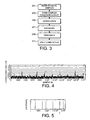
- the guard detection block 20 is illustrated schematically in Figure 2, and the method of the present invention, for determining the guard interval size, will be described with reference to Figure 2, and to Figure 3, which is a flow chart illustrating the method according to the invention.
- the method of Figure 3 includes a first step, step 201, of receiving the digital samples at respective I and Q inputs 22. For each sample, the complex conjugate of the sample is formed, and the sample is applied to a delay block 24, in step 203.
- the delay block 24 is a FIFO buffer of A taps, and thus applies a delay equivalent to the duration of A samples, where A is the FFT size (that is, 2048 in 2k mode or 8192 in 8k mode), and is the duration of the active part of the symbol, expressed in samples.
- a correlation function is calculated in a multiplication block 26, by multiplying each input symbol with the appropriate symbol obtained in step 203 with the delay applied thereto, thereby obtaining a measure of the correlation between them.
- the output average value is then obtained by applying the result from block 28 to a block 30, which takes the modulus of the output complex numbers.
- the calculated correlation function is a measure of the degree to which each sample is correlated with the sample appearing in the input signal after a particular delay.
- the function is averaged over time to provide a measure of the correlation between a particular sequence of samples and the sequence of samples appearing after that delay. Since it is known that the guard interval contains samples which are repeats of samples from the active symbol appearing later in the signal, a high value of the correlation function may be an indication that it is the samples of the guard interval that are being examined.
- Figure 4 is an explanatory graph of the value of this averaged correlation function, obtained from block 30, showing how it varies over a large number of samples, for one particular set of trial data.
- the correlation function has a value which varies in an unpredictable way, because of chance correlations between the samples at different times, but which includes a number of peaks. These peaks can again arise because of chance correlations, or may arise because it is the samples of the guard interval which are under examination.
- step 209 the value of the correlation function is then compared with a threshold value in a thresholding block 32, and it is only positions at which the value of the correlation function exceeds the threshold value which are investigated further, in order to determine whether the large value of the correlation function is due to chance or indicates the position of the guard interval.
- a counter 34 is connected to the thresholding block 32, and used to create a dead period immediately after the threshold is crossed, during which the output is zero. The length of the dead period may for example be half of one symbol period.
- the use of the threshold value and dead period provide robustness.
- the presence of multipath and/or co-channel interference can distort the shape of the peak in the correlation function. However, it will not remove the rising edge of the peak.
- the use of the threshold value means that the method relies not on the shape of the peak (which is subject to this distortion), but on the periodicity of the peaks (which is not significantly affected by the interference).
- the use of the dead period ensures that multiple successive spurious peaks are not recorded.
- the threshold value is clearly important. If the value is too high, some of the points of potential interest will be missed, while, if it is too low, too many points will be examined, possibly leading to an inaccurate estimate of the guard interval size. It may be possible to set the threshold in initial settings of the receiver circuit. Alternatively, a further algorithm can adjust the threshold value, by starting with a high value, and reducing it until a stable value of the guard interval size is obtained. A further alternative is to measure the range of the correlation signals and to set the threshold at a fraction of the maximum. For example, values in the range of 0.6 to 0.8 of the maximum have been found to work. It is assumed hereafter that a suitable threshold has been adopted.
- Figure 5 shows the points at which the value of the correlation function exceeds the threshold value. Based on the particular correlation function illustrated in Figure 4, the points shown in Figure 5 are in fact obtained by using a threshold value of 0.8.
- This procedure is then repeated until either a predetermined number of samples have been examined, or a predetermined number of points have been obtained.
- the spacing of the spikes in the graph of Figure 5 will indicate which guard interval is present. However, it is difficult to measure this directly for two reasons. Firstly, some spikes are missing, where the peaks did not reach the threshold set in the thresholding block 32. Secondly, the exact location of the spikes is noisy, due to channel noise and self-noise, which mean that the positions of peaks in the correlation are subject to noise. Thirdly, some peaks will be due to noise only, particularly where the threshold has been set too low, or where the noise power is high.
- each of a number of comb filters 34 is applied to the detected series of points at which the threshold is exceeded. This is shown schematically in Figure 2.
- Each comb filter 34 has a pattern of zeroes and ones, the ones forming the teeth of the comb.
- the teeth of the comb have a finite width, which deals with the lateral positional noise in the spacing of the spikes. Moreover, the fact that some spikes will be missing from the series, as discussed above, is dealt with by providing a large number of teeth.
- Figure 2 shows a comb filter in which the teeth have a width of four samples and a spacing of nine samples.
- each comb filter 34 The outputs from each comb filter 34 are summed in a block 36, and added into an accumulator forming part of a circular buffer 38. The pointer then moves on to the next accumulator. At the end of the buffer, it jumps back to the start.
- comb filter 34 for each possible guard interval size
- buffer connected to each comb filter, and hence one buffer for each possible guard interval size. It should be noted that, because the different possible guard sizes are tested for in parallel, the time taken to complete the process is largely independent of the number of possible sizes.
- the described technique uses large amounts of memory within the receiver. However, it is only necessary to perform the required guard interval size detection once, during an acquisition phase, at a time when there is a large amount of RAM in the receiver which is not being used for other purposes.
- a correlation value is calculated between a first function which comprises a series of regularly spaced delta functions (the comb filter), and a second function which comprises a delta function at each of the positions at which the correlation exceeds the threshold.
- the spikes will line up with the teeth, and give a high output.
- the output will be low, because the spikes will align mainly with zeroes in the comb filter.
- the results must be averaged over many symbols because, if the transmitted signal had a guard size equal to 1/4 of the active symbol size, part of the symbol would align with the comb filter teeth even for the comb which is detecting the 1/32 guard size.
- This partial overlap is removed by the averaging process, because the alignment would occur at different points in the buffer.
- the averaging process also deals with the problem of missing spikes, or spikes occurring due to noise only.
- Outputs from the buffers 38 are supplied to MAX blocks 40, which find the positions, and heights, of the biggest accumulator outputs.
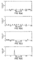
- Figure 6 shows the result of this process for the data used in Figures 3 and 4. Specifically, Figure 6(a) shows the output of the comb filter corresponding to a guard interval size of 1/4 FFT size (512 samples); Figure 6(b) shows the output of the comb filter corresponding to a guard interval size of 1/8 FFT size (256 samples); Figure 6(c) shows the output of the comb filter corresponding to a guard interval size of 1/16 FFT size (128 samples); and Figure 6(d) shows the output of the comb filter corresponding to a guard interval size of 1/32 FFT size (64 samples).
- Figure 6(a) shows the output of the comb filter corresponding to a guard interval size of 1/4 FFT size (512 samples)
- Figure 6(b) shows the output of the comb filter corresponding to a guard interval size of 1/8 FFT size (256 samples)
- Figure 6(c) shows the output of the comb filter corresponding to a guard interval size of 1/16 FFT size (128 samples)
- Figure 6(d) shows the output of
- Outputs from the MAX blocks 40 are supplied to a further MAX block 42, which outputs the index of whichever input was the largest.
- the position of the peak can be used to determine the position of the start of each symbol.
- the position of the peak within the circular buffer indicates the position along the input stream of samples at which the averaging window aligns directly with the cyclic prefix. This allows the position of the start of the active part of the symbol to be calculated, at least approximately, very quickly. This means that the acquisition phase of operation of the receiver can be completed quickly.
- the method is robust in noise, and also robust enough to handle signals with severe multipath and/or co-channel interference. Moreover, the method is of low complexity, and can be implemented in a VLSI.
Landscapes
- Engineering & Computer Science (AREA)
- Signal Processing (AREA)
- Multimedia (AREA)
- Computer Networks & Wireless Communication (AREA)
- Noise Elimination (AREA)
- Input Circuits Of Receivers And Coupling Of Receivers And Audio Equipment (AREA)
- Burglar Alarm Systems (AREA)
- Circuits Of Receivers In General (AREA)
Claims (8)
- Procédé de traitement d'un signal reçu, en vue de déterminer la taille d'un intervalle de garde dans celui-ci, le procédé comportant les étapes consistant à :former des échantillons numériques (201, 203) du signal reçu ;générer (205, 207) à partir des échantillons numériques une fonction de corrélation avec des crêtes à des positions qui sont déterminées par la taille de l'intervalle de garde et une position de l'intervalle de garde dans le signal reçu ;déterminer (209) une série d'emplacements d'échantillons auxquels la fonction de corrélation excède un seuil prédéterminé ; caractérisé par les étapes consistant à :appliquer (211) une pluralité de filtres en peigne, chacun correspondant à une taille d'intervalle de garde possible, à la série d'emplacement d'échantillons ; etdéterminer la taille d'intervalle de garde à partir de sorties desdits filtres en peigne.
- Procédé selon la revendication 1, comportant l'étape consistant à générer la fonction de corrélation en :appliquant un retard prédéterminé aux échantillons numériques ; etcalculant la fonction de corrélation à partir d'une corrélation entre une séquence d'échantillons numériques et une séquence d'échantillons numériques ayant un retard qui lui est appliqué.
- Procédé selon la revendication 1, comportant l'étape consistant à additionner les sorties à partir de chacun des filtres en peigne.
- Procédé selon la revendication 1, dans lequel chaque filtre en peigne présente une pluralité de dents, avec un espace correspondant à la taille d'un symbole formé par un symbole actif et la taille d'intervalle de garde possible correspondante.
- Procédé selon la revendication 1, comportant l'étape consistant à déterminer la taille d'intervalle de garde en déterminant lequel parmi les filtres en peigne génère une sortie qui indique que des crêtes dans ladite fonction de corrélation sont occasionnées à des positions qui sont espacées par une séparation correspondant à la taille d'un symbole formé par un symbole actif et la taille d'intervalle de garde possible correspondante.
- Procédé selon la revendication 1, dans lequel l'étape consistant à déterminer la série d'emplacements d'échantillons comporte l'étape consistant à appliquer une période d'inactivité, de sorte que des emplacements d'échantillons successifs multiples ne puissent pas être enregistrés.
- Circuit de réception, en vue du traitement d'un signal reçu afin de déterminer une taille d'un intervalle de garde dans celui-ci, comportant :un échantillonneur (2) en vue de former des échantillons numériques du signal reçu ;un corrélateur (26, 28, 30) en vue de générer à partir des échantillons numériques une fonction de corrélation avec des crêtes à des positions qui sont déterminées par la taille de l'intervalle de garde et une position de l'intervalle de garde dans le signal reçu ; et caractérisé parune pluralité de filtres en peigne (34), chacun correspondant à une taille d'intervalle de garde possible, chacun recevant une série d'emplacements d'échantillons auxquels la fonction de corrélation excède un seuil prédéterminé à la série d'emplacements d'échantillons, chacun générant une sortie en vue de déterminer la taille d'intervalle de garde à partir de cela.
- Circuit de réception selon la revendication 7, comportant en outre :une pluralité de tampons d'accumulateurs, chacun correspondant à filtre respectif d'une pluralité de filtres en peigne, en vue d'additionner les sorties à partir de cela ; etdes moyens en vue de déterminer lequel parmi lesdits tampons d'accumulateurs génère le niveau de sortie maximum.
Applications Claiming Priority (3)
| Application Number | Priority Date | Filing Date | Title |
|---|---|---|---|
| GB0017131 | 2000-07-12 | ||
| GB0017131A GB2364865B (en) | 2000-07-12 | 2000-07-12 | Receiver circuit |
| PCT/EP2001/007655 WO2002009383A1 (fr) | 2000-07-12 | 2001-07-04 | Circuit de reception |
Publications (2)
| Publication Number | Publication Date |
|---|---|
| EP1302044A1 EP1302044A1 (fr) | 2003-04-16 |
| EP1302044B1 true EP1302044B1 (fr) | 2007-11-14 |
Family
ID=9895534
Family Applications (1)
| Application Number | Title | Priority Date | Filing Date |
|---|---|---|---|
| EP01954007A Expired - Lifetime EP1302044B1 (fr) | 2000-07-12 | 2001-07-04 | Circuit de reception |
Country Status (6)
| Country | Link |
|---|---|
| US (2) | US7424048B2 (fr) |
| EP (1) | EP1302044B1 (fr) |
| AT (1) | ATE378761T1 (fr) |
| DE (1) | DE60131407T2 (fr) |
| GB (1) | GB2364865B (fr) |
| WO (1) | WO2002009383A1 (fr) |
Families Citing this family (23)
| Publication number | Priority date | Publication date | Assignee | Title |
|---|---|---|---|---|
| GB2364865B (en) * | 2000-07-12 | 2004-01-21 | Conexant Systems Inc | Receiver circuit |
| US8483189B2 (en) | 2003-03-10 | 2013-07-09 | Panasonic Corporation | OFDM signal transmission method, transmission apparatus, and reception apparatus |
| JP4291674B2 (ja) | 2003-11-11 | 2009-07-08 | 株式会社エヌ・ティ・ティ・ドコモ | Ofdm送信機及びofdm受信機 |
| DE602004029754D1 (de) | 2003-12-08 | 2010-12-09 | Panasonic Corp | Demodulator und Demodulationsmethode und integrierter Schaltkreis des Demodulators |
| US8000675B2 (en) * | 2004-04-16 | 2011-08-16 | Sony Ericsson Mobile Communications Ab | Low cost method for receiving broadcast channels with a cellular terminal |
| CN1951023A (zh) * | 2004-04-29 | 2007-04-18 | 皇家飞利浦电子股份有限公司 | 用于窄带干扰消除的接收机 |
| CN1860753A (zh) * | 2004-06-08 | 2006-11-08 | 桑德布里奇技术公司 | 正交频分多路复用接收器 |
| KR100674918B1 (ko) * | 2004-11-05 | 2007-01-26 | 삼성전자주식회사 | Mcm 신호 수신 시스템에서의 임펄스 잡음 제거 회로 |
| US7570666B2 (en) * | 2005-02-01 | 2009-08-04 | Industrial Technology Research Institute | Method and apparatus for guard interval detection in multi-carrier receiver |
| US7693227B2 (en) * | 2005-03-31 | 2010-04-06 | Texas Instruments Incorporated | Channel length estimation and accurate FFT window placement for high-mobility OFDM receivers in single frequency networks |
| US7602852B2 (en) * | 2005-04-21 | 2009-10-13 | Telefonaktiebolaget L M Ericsson (Publ) | Initial parameter estimation in OFDM systems |
| US7684286B2 (en) | 2005-08-31 | 2010-03-23 | Mediatek Inc. | Track-jump control device and method thereof |
| US8315191B2 (en) | 2005-09-20 | 2012-11-20 | Qualcomm Incorporated | Timing acquisition and mode and guard detection for an OFDM transmission |
| CN100514903C (zh) * | 2005-09-29 | 2009-07-15 | 王亦兵 | 频率分配用户接入局域网的系统及上、下行传输方法 |
| US7479924B2 (en) * | 2005-11-14 | 2009-01-20 | Sirf Technology Holdings, Inc. | False reacquisition mitigation in high sensitivity navigational satellite signal receivers |
| US8009745B2 (en) | 2005-11-15 | 2011-08-30 | Qualcomm Incorporated | Time tracking for a receiver with guard interval correlation |
| TWI313122B (en) * | 2006-09-14 | 2009-08-01 | Transmission parameter recognition apparatus and method thereof | |
| US7684445B2 (en) * | 2006-10-09 | 2010-03-23 | Industrial Technology Research Institute | Method and related circuit of guard interval length detection for OFDM signals |
| US8054925B2 (en) | 2007-07-31 | 2011-11-08 | Alcatel Lucent | Method and apparatus for synchronizing a receiver |
| GB2470755A (en) | 2009-06-03 | 2010-12-08 | Sony Corp | Data processing apparatus and method |
| US20120157865A1 (en) * | 2010-12-20 | 2012-06-21 | Yosef Stein | Adaptive ecg wandering correction |
| US9042467B2 (en) | 2013-05-01 | 2015-05-26 | Delphi Technologies, Inc. | Method to increase signal-to-noise ratio of a cyclic-prefix orthogonal frequency-division multiplex signal |
| US10524161B2 (en) | 2014-08-20 | 2019-12-31 | Qualcomm Incorporated | Delay spread estimation and utilization |
Family Cites Families (8)
| Publication number | Priority date | Publication date | Assignee | Title |
|---|---|---|---|---|
| FR881804A (fr) | 1941-03-11 | 1943-05-10 | Procédé de fabrication continue d'objets, en particulier d'éléments de dentiers, e dents factices et similaires | |
| JP3041175B2 (ja) * | 1993-11-12 | 2000-05-15 | 株式会社東芝 | Ofdm同期復調回路 |
| US5528405A (en) * | 1995-01-05 | 1996-06-18 | Harris Corporation | Power series correction in a linear fiber optic analog transmission system and method |
| FR2743967B1 (fr) * | 1996-01-18 | 1998-03-27 | France Telecom | Procede et dispositif de synchronisation temporelle d'un recepteur d'un signal multiporteuse |
| JPH1065605A (ja) * | 1996-08-23 | 1998-03-06 | Sony Corp | 受信方法、タイミング検出装置及び受信装置 |
| GB9709063D0 (en) * | 1997-05-02 | 1997-06-25 | British Broadcasting Corp | Improvements to OFDM symbol synchronization |
| FR2764143A1 (fr) * | 1997-05-27 | 1998-12-04 | Philips Electronics Nv | Procede de determination d'un format d'emission de symboles dans un systeme de transmission et systeme |
| GB2364865B (en) * | 2000-07-12 | 2004-01-21 | Conexant Systems Inc | Receiver circuit |
-
2000
- 2000-07-12 GB GB0017131A patent/GB2364865B/en not_active Expired - Fee Related
-
2001
- 2001-07-04 EP EP01954007A patent/EP1302044B1/fr not_active Expired - Lifetime
- 2001-07-04 WO PCT/EP2001/007655 patent/WO2002009383A1/fr not_active Ceased
- 2001-07-04 AT AT01954007T patent/ATE378761T1/de not_active IP Right Cessation
- 2001-07-04 DE DE60131407T patent/DE60131407T2/de not_active Expired - Lifetime
-
2003
- 2003-01-10 US US10/340,854 patent/US7424048B2/en not_active Expired - Fee Related
-
2008
- 2008-08-06 US US12/187,220 patent/US7729414B2/en not_active Expired - Fee Related
Also Published As
| Publication number | Publication date |
|---|---|
| WO2002009383A1 (fr) | 2002-01-31 |
| US20090154610A1 (en) | 2009-06-18 |
| GB2364865B (en) | 2004-01-21 |
| US20030219084A1 (en) | 2003-11-27 |
| ATE378761T1 (de) | 2007-11-15 |
| GB2364865A (en) | 2002-02-06 |
| GB0017131D0 (en) | 2000-08-30 |
| US7424048B2 (en) | 2008-09-09 |
| EP1302044A1 (fr) | 2003-04-16 |
| US7729414B2 (en) | 2010-06-01 |
| DE60131407T2 (de) | 2008-09-18 |
| DE60131407D1 (de) | 2007-12-27 |
Similar Documents
| Publication | Publication Date | Title |
|---|---|---|
| US7729414B2 (en) | Guard interval analysis method and apparatus | |
| US7916815B2 (en) | Method and apparatus for a multicarrier receiver circuit with guard interval size detection | |
| CA2472319C (fr) | Detection et mesure des interferences contenues dans une porteuse numerique | |
| US7778363B2 (en) | Synchronization timing detecting apparatus, receiving apparatus, and synchronization timing detecting method | |
| US20060233225A1 (en) | Frequency synchronization apparatus and frequency synchronization method | |
| KR100518600B1 (ko) | 가드 인터벌 및 고속 푸리에 변환 모드 검출기를 구비하는디지털 비디오 방송 수신기, 및 그 방법 | |
| US6584092B1 (en) | Apparatus and method for OFDM communication | |
| US7570666B2 (en) | Method and apparatus for guard interval detection in multi-carrier receiver | |
| EP1079579B1 (fr) | Trame de synchronisation en OFDM | |
| US7616723B2 (en) | Method for symbol timing synchronization and apparatus thereof | |
| JP3960511B2 (ja) | Ofdm信号解析装置 | |
| JP3686538B2 (ja) | 受信装置 | |
| JP3896120B2 (ja) | シンボル時間推定器及びこれを用いた無線受信装置 | |
| KR101080968B1 (ko) | 디지털방송용 단말기 및 디지털방송용 단말기의 보호구간을이용한 프레임동기 검출 방법 | |
| JP2006203291A (ja) | 受信装置 | |
| JP5478451B2 (ja) | 遅延プロファイル測定装置及びプログラム | |
| JP3576414B2 (ja) | Ofdm受信装置 | |
| JP2006203290A (ja) | 受信装置 |
Legal Events
| Date | Code | Title | Description |
|---|---|---|---|
| PUAI | Public reference made under article 153(3) epc to a published international application that has entered the european phase |
Free format text: ORIGINAL CODE: 0009012 |
|
| 17P | Request for examination filed |
Effective date: 20030205 |
|
| AK | Designated contracting states |
Designated state(s): AT BE CH CY DE DK ES FI FR GB GR IE IT LI LU MC NL PT SE TR |
|
| RBV | Designated contracting states (corrected) |
Designated state(s): AT BE CH CY DE DK ES FI FR GR IE IT LI LU MC NL PT SE TR |
|
| GRAP | Despatch of communication of intention to grant a patent |
Free format text: ORIGINAL CODE: EPIDOSNIGR1 |
|
| GRAS | Grant fee paid |
Free format text: ORIGINAL CODE: EPIDOSNIGR3 |
|
| GRAA | (expected) grant |
Free format text: ORIGINAL CODE: 0009210 |
|
| AK | Designated contracting states |
Kind code of ref document: B1 Designated state(s): AT BE CH CY DE DK ES FI FR GR IE IT LI LU MC NL PT SE TR |
|
| REG | Reference to a national code |
Ref country code: CH Ref legal event code: EP |
|
| REG | Reference to a national code |
Ref country code: IE Ref legal event code: FG4D |
|
| REF | Corresponds to: |
Ref document number: 60131407 Country of ref document: DE Date of ref document: 20071227 Kind code of ref document: P |
|
| PG25 | Lapsed in a contracting state [announced via postgrant information from national office to epo] |
Ref country code: CH Free format text: LAPSE BECAUSE OF FAILURE TO SUBMIT A TRANSLATION OF THE DESCRIPTION OR TO PAY THE FEE WITHIN THE PRESCRIBED TIME-LIMIT Effective date: 20071114 Ref country code: SE Free format text: LAPSE BECAUSE OF FAILURE TO SUBMIT A TRANSLATION OF THE DESCRIPTION OR TO PAY THE FEE WITHIN THE PRESCRIBED TIME-LIMIT Effective date: 20080214 Ref country code: ES Free format text: LAPSE BECAUSE OF FAILURE TO SUBMIT A TRANSLATION OF THE DESCRIPTION OR TO PAY THE FEE WITHIN THE PRESCRIBED TIME-LIMIT Effective date: 20080225 Ref country code: LI Free format text: LAPSE BECAUSE OF FAILURE TO SUBMIT A TRANSLATION OF THE DESCRIPTION OR TO PAY THE FEE WITHIN THE PRESCRIBED TIME-LIMIT Effective date: 20071114 |
|
| REG | Reference to a national code |
Ref country code: CH Ref legal event code: PL |
|
| ET | Fr: translation filed | ||
| PG25 | Lapsed in a contracting state [announced via postgrant information from national office to epo] |
Ref country code: AT Free format text: LAPSE BECAUSE OF FAILURE TO SUBMIT A TRANSLATION OF THE DESCRIPTION OR TO PAY THE FEE WITHIN THE PRESCRIBED TIME-LIMIT Effective date: 20071114 |
|
| PG25 | Lapsed in a contracting state [announced via postgrant information from national office to epo] |
Ref country code: DK Free format text: LAPSE BECAUSE OF FAILURE TO SUBMIT A TRANSLATION OF THE DESCRIPTION OR TO PAY THE FEE WITHIN THE PRESCRIBED TIME-LIMIT Effective date: 20071114 |
|
| PG25 | Lapsed in a contracting state [announced via postgrant information from national office to epo] |
Ref country code: BE Free format text: LAPSE BECAUSE OF FAILURE TO SUBMIT A TRANSLATION OF THE DESCRIPTION OR TO PAY THE FEE WITHIN THE PRESCRIBED TIME-LIMIT Effective date: 20071114 |
|
| PLBE | No opposition filed within time limit |
Free format text: ORIGINAL CODE: 0009261 |
|
| STAA | Information on the status of an ep patent application or granted ep patent |
Free format text: STATUS: NO OPPOSITION FILED WITHIN TIME LIMIT |
|
| PG25 | Lapsed in a contracting state [announced via postgrant information from national office to epo] |
Ref country code: PT Free format text: LAPSE BECAUSE OF FAILURE TO SUBMIT A TRANSLATION OF THE DESCRIPTION OR TO PAY THE FEE WITHIN THE PRESCRIBED TIME-LIMIT Effective date: 20080414 |
|
| 26N | No opposition filed |
Effective date: 20080815 |
|
| PG25 | Lapsed in a contracting state [announced via postgrant information from national office to epo] |
Ref country code: GR Free format text: LAPSE BECAUSE OF FAILURE TO SUBMIT A TRANSLATION OF THE DESCRIPTION OR TO PAY THE FEE WITHIN THE PRESCRIBED TIME-LIMIT Effective date: 20080215 |
|
| PG25 | Lapsed in a contracting state [announced via postgrant information from national office to epo] |
Ref country code: MC Free format text: LAPSE BECAUSE OF NON-PAYMENT OF DUE FEES Effective date: 20080731 |
|
| PG25 | Lapsed in a contracting state [announced via postgrant information from national office to epo] |
Ref country code: IE Free format text: LAPSE BECAUSE OF NON-PAYMENT OF DUE FEES Effective date: 20080704 Ref country code: CY Free format text: LAPSE BECAUSE OF FAILURE TO SUBMIT A TRANSLATION OF THE DESCRIPTION OR TO PAY THE FEE WITHIN THE PRESCRIBED TIME-LIMIT Effective date: 20071114 |
|
| PG25 | Lapsed in a contracting state [announced via postgrant information from national office to epo] |
Ref country code: FI Free format text: LAPSE BECAUSE OF FAILURE TO SUBMIT A TRANSLATION OF THE DESCRIPTION OR TO PAY THE FEE WITHIN THE PRESCRIBED TIME-LIMIT Effective date: 20071114 |
|
| REG | Reference to a national code |
Ref country code: FR Ref legal event code: TP |
|
| NLS | Nl: assignments of ep-patents |
Owner name: NXP B.V. Effective date: 20100202 |
|
| PG25 | Lapsed in a contracting state [announced via postgrant information from national office to epo] |
Ref country code: LU Free format text: LAPSE BECAUSE OF NON-PAYMENT OF DUE FEES Effective date: 20080704 |
|
| PG25 | Lapsed in a contracting state [announced via postgrant information from national office to epo] |
Ref country code: TR Free format text: LAPSE BECAUSE OF FAILURE TO SUBMIT A TRANSLATION OF THE DESCRIPTION OR TO PAY THE FEE WITHIN THE PRESCRIBED TIME-LIMIT Effective date: 20071114 |
|
| REG | Reference to a national code |
Ref country code: NL Ref legal event code: SD Effective date: 20101025 |
|
| REG | Reference to a national code |
Ref country code: DE Ref legal event code: R084 Ref document number: 60131407 Country of ref document: DE Effective date: 20110426 |
|
| REG | Reference to a national code |
Ref country code: FR Ref legal event code: TP Owner name: TRIDENT MICROSYSTEMS (FAR EAST) LTD., KY Effective date: 20120418 |
|
| REG | Reference to a national code |
Ref country code: DE Ref legal event code: R082 Ref document number: 60131407 Country of ref document: DE Representative=s name: EPPING HERMANN FISCHER, PATENTANWALTSGESELLSCH, DE |
|
| REG | Reference to a national code |
Ref country code: DE Ref legal event code: R082 Ref document number: 60131407 Country of ref document: DE Representative=s name: EPPING HERMANN FISCHER, PATENTANWALTSGESELLSCH, DE Effective date: 20121023 Ref country code: DE Ref legal event code: R081 Ref document number: 60131407 Country of ref document: DE Owner name: ENTROPIC COMMUNICATIONS, INC., US Free format text: FORMER OWNER: TRIDENT MICROSYSTEMS (FAR EAST) LTD., GRAND CAYMAN, KY Effective date: 20121023 Ref country code: DE Ref legal event code: R081 Ref document number: 60131407 Country of ref document: DE Owner name: ENTROPIC COMMUNICATIONS, INC., SAN DIEGO, US Free format text: FORMER OWNER: TRIDENT MICROSYSTEMS (FAR EAST) LTD., GRAND CAYMAN, KY Effective date: 20121023 |
|
| REG | Reference to a national code |
Ref country code: NL Ref legal event code: SD Effective date: 20130916 |
|
| PGFP | Annual fee paid to national office [announced via postgrant information from national office to epo] |
Ref country code: NL Payment date: 20130726 Year of fee payment: 13 Ref country code: DE Payment date: 20130729 Year of fee payment: 13 |
|
| PGFP | Annual fee paid to national office [announced via postgrant information from national office to epo] |
Ref country code: FR Payment date: 20130717 Year of fee payment: 13 |
|
| REG | Reference to a national code |
Ref country code: FR Ref legal event code: TP Owner name: ENTROPIC COMMUNICATIONS, INC., US Effective date: 20131119 |
|
| PGFP | Annual fee paid to national office [announced via postgrant information from national office to epo] |
Ref country code: IT Payment date: 20130724 Year of fee payment: 13 |
|
| REG | Reference to a national code |
Ref country code: DE Ref legal event code: R119 Ref document number: 60131407 Country of ref document: DE |
|
| REG | Reference to a national code |
Ref country code: NL Ref legal event code: V1 Effective date: 20150201 |
|
| PG25 | Lapsed in a contracting state [announced via postgrant information from national office to epo] |
Ref country code: NL Free format text: LAPSE BECAUSE OF NON-PAYMENT OF DUE FEES Effective date: 20150201 |
|
| REG | Reference to a national code |
Ref country code: FR Ref legal event code: ST Effective date: 20150331 |
|
| PG25 | Lapsed in a contracting state [announced via postgrant information from national office to epo] |
Ref country code: IT Free format text: LAPSE BECAUSE OF NON-PAYMENT OF DUE FEES Effective date: 20140704 Ref country code: DE Free format text: LAPSE BECAUSE OF NON-PAYMENT OF DUE FEES Effective date: 20150203 |
|
| REG | Reference to a national code |
Ref country code: DE Ref legal event code: R119 Ref document number: 60131407 Country of ref document: DE Effective date: 20150203 |
|
| PG25 | Lapsed in a contracting state [announced via postgrant information from national office to epo] |
Ref country code: FR Free format text: LAPSE BECAUSE OF NON-PAYMENT OF DUE FEES Effective date: 20140731 |