EP1302100A2 - Dispositif et méthode pour traiter un pis - Google Patents
Dispositif et méthode pour traiter un pis Download PDFInfo
- Publication number
- EP1302100A2 EP1302100A2 EP02022838A EP02022838A EP1302100A2 EP 1302100 A2 EP1302100 A2 EP 1302100A2 EP 02022838 A EP02022838 A EP 02022838A EP 02022838 A EP02022838 A EP 02022838A EP 1302100 A2 EP1302100 A2 EP 1302100A2
- Authority
- EP
- European Patent Office
- Prior art keywords
- sensor
- carrier
- obstacle
- signal
- animal
- Prior art date
- Legal status (The legal status is an assumption and is not a legal conclusion. Google has not performed a legal analysis and makes no representation as to the accuracy of the status listed.)
- Withdrawn
Links
- 210000000481 breast Anatomy 0.000 title claims abstract description 31
- 238000000034 method Methods 0.000 title claims abstract description 15
- 238000004140 cleaning Methods 0.000 claims abstract description 37
- 230000000249 desinfective effect Effects 0.000 claims abstract description 8
- 241001465754 Metazoa Species 0.000 claims description 60
- 238000011282 treatment Methods 0.000 claims description 43
- 238000011156 evaluation Methods 0.000 claims description 22
- 239000012530 fluid Substances 0.000 claims description 6
- 238000012544 monitoring process Methods 0.000 claims description 3
- 230000008859 change Effects 0.000 claims description 2
- 241000283690 Bos taurus Species 0.000 abstract description 13
- 210000002445 nipple Anatomy 0.000 description 12
- 210000000003 hoof Anatomy 0.000 description 5
- 230000009471 action Effects 0.000 description 4
- 230000006378 damage Effects 0.000 description 4
- 239000008267 milk Substances 0.000 description 4
- 210000004080 milk Anatomy 0.000 description 4
- 235000013336 milk Nutrition 0.000 description 4
- 230000008569 process Effects 0.000 description 4
- 230000004888 barrier function Effects 0.000 description 3
- PEDCQBHIVMGVHV-UHFFFAOYSA-N Glycerine Chemical compound OCC(O)CO PEDCQBHIVMGVHV-UHFFFAOYSA-N 0.000 description 2
- 239000000645 desinfectant Substances 0.000 description 2
- 238000001514 detection method Methods 0.000 description 2
- 238000011161 development Methods 0.000 description 2
- 238000004659 sterilization and disinfection Methods 0.000 description 2
- 230000000638 stimulation Effects 0.000 description 2
- 241000282979 Alces alces Species 0.000 description 1
- 235000002198 Annona diversifolia Nutrition 0.000 description 1
- 241000282832 Camelidae Species 0.000 description 1
- 241000282836 Camelus dromedarius Species 0.000 description 1
- 241000283707 Capra Species 0.000 description 1
- 241000283086 Equidae Species 0.000 description 1
- 241000283074 Equus asinus Species 0.000 description 1
- 241000282838 Lama Species 0.000 description 1
- 241000124008 Mammalia Species 0.000 description 1
- 241001494479 Pecora Species 0.000 description 1
- 241000282941 Rangifer tarandus Species 0.000 description 1
- 238000006243 chemical reaction Methods 0.000 description 1
- 239000003795 chemical substances by application Substances 0.000 description 1
- 238000011109 contamination Methods 0.000 description 1
- 238000007598 dipping method Methods 0.000 description 1
- 238000006073 displacement reaction Methods 0.000 description 1
- 235000011187 glycerol Nutrition 0.000 description 1
- 238000009434 installation Methods 0.000 description 1
- 238000000691 measurement method Methods 0.000 description 1
- 230000003287 optical effect Effects 0.000 description 1
- 230000004044 response Effects 0.000 description 1
- 230000035939 shock Effects 0.000 description 1
- 230000004936 stimulating effect Effects 0.000 description 1
- 239000000126 substance Substances 0.000 description 1
- 238000012549 training Methods 0.000 description 1
Images
Classifications
-
- A—HUMAN NECESSITIES
- A01—AGRICULTURE; FORESTRY; ANIMAL HUSBANDRY; HUNTING; TRAPPING; FISHING
- A01J—MANUFACTURE OF DAIRY PRODUCTS
- A01J7/00—Accessories for milking machines or devices
- A01J7/04—Accessories for milking machines or devices for treatment of udders or teats, e.g. for cleaning
-
- A—HUMAN NECESSITIES
- A01—AGRICULTURE; FORESTRY; ANIMAL HUSBANDRY; HUNTING; TRAPPING; FISHING
- A01J—MANUFACTURE OF DAIRY PRODUCTS
- A01J5/00—Milking machines or devices
- A01J5/017—Automatic attaching or detaching of clusters
- A01J5/0175—Attaching of clusters
Definitions
- the present invention is in the field of milking animals, in particular of cows.
- the present invention relates to the treatment of udders animals to be milked.
- Treating here means the steps preparing for milking, such as e.g. cleaning and, if necessary, disinfecting or stimulating the Udder before milking.
- the udder of the milk to be milked before milking Animal pretreated, e.g. the udder is cleaned.
- the term also includes "Treat” in the sense of this application which e.g. separate treatment of the udder after milking. This may include repeated cleaning or the Apply a disinfectant and / or care product to the teat or udder all in all.
- the udder becomes a cylindrical one which is rotatably mounted on the free end of a movable support Brush from a starting position to an end position in which the brush is in the active position with the udder, proceed.
- the brush is driven to rotate the teats and to clean the udder overall.
- the cleaning process is finished Use the brush to move the carrier back to the starting position. There the brush itself cleaned and disinfected.
- the problem underlying the present invention is an improved device to propose the type mentioned at the beginning.
- the present invention lies in particular the problem underlying a device for cleaning the udder from to be milked Propose animals that are free in the cleaning station, i.e. who are not in the Cleaning station are fixed.
- this object is achieved by a device with the features of Claim 1 and solved by a method with the features of claim 13.
- preferred Further training is the subject of the subclaims.
- the device according to the invention comprises at least one treatment device and at least one carrier carrying the treatment device and at least one a drive device acting on the carrier.
- the treatment facility is with the carrier from a starting position to a working position in which the treatment device is effective, movable.
- At least one sensor emits a signal when on Obstacle hinders the movement of the carrier between the starting position and the end position. The signal then indicates the presence of an obstacle.
- An evaluation device receives the signal and acts on the drive device.
- the method according to the invention for treating an udder to be milked Animal is carried out with a treatment device that by means of a drive device from a starting position, which e.g. located next to the animal, in a Action is taken to treat the udder of the animal to be milked. If in the path of movement of the wearer between the initial position and the active position If there is an obstacle, this is detected by a sensor. The sensor gives a signal which indicates the presence of an obstacle. This signal is from recorded and evaluated by an evaluation device, whereupon the drive device is acted on to avoid bumps that are painful for an animal or are dangerous.
- the device and the method according to the invention have many Benefits.
- a difference to known automatic systems for teat location or teat cup attachment is, for example, that in a treatment device according to the invention a collision should be avoided while using an automatic teat locator a contact is currently being sought. This results in different requirements and objectives of accuracy and stability of the device. Teat location systems require teats with known teat shapes to be precise and targeted recognize and control. A treatment device, on the other hand, has to be different Detect shaped obstacles reliably and painful for an animal or avoid heavy collisions.
- An obstacle is recognized with the device according to the invention and upon detection an obstacle affects the movement of the wearer.
- the Movement of the carrier e.g. to be stopped only with the forward movement to continue in the active or treatment situation when the obstacle is out of the movement path the facility has been removed.
- the obstacle an animal leg was formed.
- the treatment facility is located in one Fall into action only when the animal has its leg out of the trajectory the facility e.g. has moved away.
- the invention is described below with respect to the treatment of the udders of cows. However, it should be noted that the invention is used in all animals can give off the milk.
- the treatment device according to the invention - in a corresponding constructive size adjustment - for treatment the udder of cows, sheep, goats, horses, donkeys, camels, llamas and dromedaries, Elk, reindeer and buffalo and other mammals.
- the treatment can be done before and / or after milking.
- the device according to the invention it is thus possible to make one painful for the animal Collision of the treatment facility when the ancestor is in the active or end position prevent. Painful collisions with the device or the carrier for the animal are avoided. In the same way, the treatment device is spared, since no strong unforeseen impacts on the device or the wearer and its drive unit act.
- the carrier is in a first direction and at least in a second direction towards the animal to be milked and in particular the animal to be treated Udder designed to be movable.
- the second direction of movement is preferred essentially perpendicular to the first direction of movement.
- Such a positioning enables a targeted installation of the device on the Udder of the animal to be treated. It turns out that the treatment facility can have a size adapted to the udders to be treated, which makes the later Cleaning and disinfecting the treatment facility between individual treatment processes on the animals to be treated is simplified.
- the animals to be milked pass through a corridor in which they first go be pretreated for milking to get to the milking stall. This includes one understands especially cleaning and / or disinfecting the udder putting on a milking cluster. After cleaning, the udder is stimulated to do this Prepare for milking.
- the device according to the invention can be used both for cleaning as well as for stimulation or both.
- the udder is usually treated by disinfecting the udder and / or maintained.
- An inventive treatment can also be used for such care treatments Device and the method according to the invention provided and adapted his.
- a care treatment such as the so-called dipping becomes a Disinfectant and care products are applied to the teat by inserting the teats into the care product be immersed.
- Such care products can also be sprayed on.
- the treatment agents can also be used for care, such as substances such as lanolyn or glycerin or the like included.
- the senor an obstacle to the movement in at least one direction recognizable.
- An obstacle in the first and at least the second direction is preferred recognizable.
- the delivery of the device to the end position in an orthogonal Coordinate system can then be both the movement in the first direction also the movement in the second direction may be stopped if necessary there is an obstacle in the way of the delivery movement.
- a three-dimensional Movability of the treatment device along three e.g. orthogonal axes obstacle detection in three dimensions is also possible and preferred.
- the evaluation device in such a way that it acts on the drive unit such that when a the presence of the signal indicating the obstacle the direction of movement of the Drive means of the carrier at least for a short and e.g. predefined duration or distance is reversed.
- the carrier or device out of the reach of the kicking animal's leg, causing excessive Shock loads and, if necessary, destruction of the device or others milking components can be prevented.
- the sensor can be a non-contact sensor which e.g. on the carrier or the Device is attached.
- a non-contact sensor can e.g. an optical or be an ultrasonic sensor.
- sensors can be provided, the electrical Measure variables such as current, voltage, capacitance, inductance or the like.
- speed or torque sensors or feed monitoring sensors possible for the drive motor or the like.
- several similar or different sensors that also use physically different measurement methods work, can be used.
- the present invention proposes a sensor that gives a signal when the device encounters an obstacle.
- This sensor can For example, be formed by the torque of a drive motor Drive unit is monitored in the event of a sudden increase in torque when moving from the starting position into the active position upon impact of the wearer or the facility to conclude an obstacle.
- a reaction evaluation and Action
- the size of the torque itself can be used for the evaluation become.
- first or second derivatives in the mathematical sense of the measured Torque or the like possibly in connection with the absolute The size of the measured value can be used for evaluation. So it can Rise of the torque curve or another suitable variable is monitored over time be, and an alarm signal will be issued if such a size exceeds the specified dimension.
- the change in the slope of the torque curve is suitable for evaluation, because these sudden changes are particularly important makes it very visible how it can cause bumps or collisions.
- the current position of the treatment device can also be used in the evaluation or the carrier are taken into account, so the level of the threshold or the threshold value range is adapted to the current position. In local areas, where collisions are more likely, the threshold can be adjusted accordingly. Time adjustments are also possible. So you can turn off straight away different (e.g. higher) threshold values when the device is standing or accelerating be taken into account.
- the drive device comprises at least a hydraulic or pneumatic cylinder, the at least one sensor formed by a pressure sensor monitoring the fluid pressure of a cylinder chamber is.
- This configuration is based on the knowledge that a pneumatic or hydraulic drive cylinder the chamber pressure suddenly changes when the Impact an obstacle on the carrier or the device when moving up to the end position.
- the pressure sensor is arranged between the pressure chamber and a throttle is located in an outlet channel of the pressure chamber for the fluid.
- a throttle is located in an outlet channel of the pressure chamber for the fluid.
- This event is detected by the pressure sensor and in the form of an obstacle indicating signal passed to the evaluation device.
- hydraulic or pneumatic cylinders double-acting pressure cylinders are preferably used.
- a pressure sensor of the type discussed above can be used in either of the two pressure chambers be assigned to the occurrence of an obstacle both when moving to be able to react from the starting position to the end position as well as during a movement in the opposite direction.
- the present invention proposed that the presence of the device in the end position detecting end position sensor is provided, its end position signal is received by the evaluation device and that the evaluation device is prepared in such a way that the drive device of the carrier receives the Presence of an obstacle indicating signal or when receiving the end position signal is turned over.
- the Evaluation device of the circuit already provided in the prior art, the one automated resetting of the facility - possibly with a time delay - after reaching it the end position.
- the evaluation device is prepared in such a way that the device is initially in the first direction is moved until the device interacts with the first directional coordinate has reached. The device is then moved in the second direction until the Establish the effective position with regard to the second directional coordinate and thus the Overall active or end position has been reached. Even the simultaneous movement in several Dimensions is possible to e.g. to accelerate the real action.
- the device When moving along the first coordinate axis, the device essentially becomes moved perpendicular to the longitudinal extent of the animal to be treated, and until the device is placed approximately in the middle under the animal. In this position there is the greatest likelihood that when moving longitudinally of the animal to be treated, i.e. on the second coordinate axis, the facility in Can be moved towards the udder to be treated without causing a collision enters with the animal's legs.
- At least at least one threshold value setting device is assigned to a sensor.
- a sensor In this way, in particular in the case of a configuration, one acting on contact Sensor created the possibility of bumping against with a small pulse Animal leg to continue with the movement of the device directly or with a time delay, when the animal's leg is out of the path of the animal in response to the impact of the animal Facility is taken.
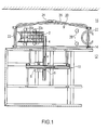
- the present invention is based on an embodiment of a cleaning device explained below as a treatment device in connection with the drawing.
- the drawing shows a schematic plan view of a milking parlor.
- the exemplary embodiment shown in the figure is a cleaning station a milking parlor, as known for example from DE-U-295 10 417 is.
- This milking parlor has several in the running direction of the animals to be milked, here Cows, boxes arranged one behind the other.
- the cleaning station is in the first box.
- a milking cluster is attached to one to be milked Cow created.
- another treatment device can also be provided according to the invention.
- stimulation, disinfection and post-treatment devices for Care and / or disinfection can be implemented according to the invention.
- a rotating brush 2 is on the free end of a carrier 4 of the cleaning device rotatably mounted.
- the carrier 4 is longitudinally displaceably mounted in a first guide 6.
- This first guide 6 will again as displaceable transversely to the guide direction of the first guide 6 in guided a second guide 8, which runs along a stationary rail 10.
- This configuration allows the brush 2 to be in an orthogonal coordinate system can be moved, the first guide 6 allowing movement in the X direction and the second guide 8 a movement in the Y direction, the through the X direction and the plane spanned in the Y direction is oriented essentially parallel to the ground is.
- the brush 2 can also be moved in the Z direction from the drawing plane his.
- the guides 6, 8 and the rail 10 are located in a technical room 12, which is separated from a passage 16 for the cows via a barrier grid 14.
- One the cows in the cleaning station receiving box 20 has at its front and at its rear Front side further grilles 22 and on its facing away from the technical room 12
- Box 20 schematically shows six footprints of a cow to be milked. These are the front pairs 28 of a large and a small hoof Animal as well as the rear hoof pairs 30a of a small animal and 30b of a large animal.
- An animal to be milked in the aisle 16 passes through the open one Inlet door 24 initially in box 20. Inlet door 24 closes automatically. Independently The size of the animal then moves to a starting position Brush located inside the technical room 12 through the barrier grid 12 into the box 20 in the X direction until the end position with respect to the X coordinate is reached.
- the rotating brush 2 is on the side next to the carrier 8. In this respect, it is likely that a possible collision with an animal leg when moving the rotating brush 2 in the box 20 by the brush 2, but not the carrier 4 is caused.
- the carrier moves 4 together with the brush 2 along the longitudinal extent of the rail 10 in the Y direction, until the cleaning position with respect to the Y direction coordinate and thus the end position has been reached.
- This can be variable and, for example, by a device are determined as they are from DE-A-199 01 241 for the rough positioning of the Milking cluster beneath a cow's udder is known.
- the first and second guides 6, 8 shown in the exemplary embodiment act conventional slot guides. Each is driven by a Drive motor, not shown here, the drive wheel on the one hand on the carrier 2nd and on the other hand acts on the rail 10. The torque of the respective motors is supervised. The corresponding signal is an evaluation device, not shown here fed.
Landscapes
- Life Sciences & Earth Sciences (AREA)
- Animal Husbandry (AREA)
- Environmental Sciences (AREA)
- Housing For Livestock And Birds (AREA)
Applications Claiming Priority (2)
| Application Number | Priority Date | Filing Date | Title |
|---|---|---|---|
| DE2001150500 DE10150500B4 (de) | 2001-10-12 | 2001-10-12 | Vorrichtung zum Bewegen einer in Wirklage mit dem Euter eines zu melkenden Tieres bringbaren Einrichtung |
| DE10150500 | 2001-10-12 |
Publications (2)
| Publication Number | Publication Date |
|---|---|
| EP1302100A2 true EP1302100A2 (fr) | 2003-04-16 |
| EP1302100A3 EP1302100A3 (fr) | 2003-11-19 |
Family
ID=7702352
Family Applications (1)
| Application Number | Title | Priority Date | Filing Date |
|---|---|---|---|
| EP02022838A Withdrawn EP1302100A3 (fr) | 2001-10-12 | 2002-10-14 | Dispositif et méthode pour traiter un pis |
Country Status (2)
| Country | Link |
|---|---|
| EP (1) | EP1302100A3 (fr) |
| DE (1) | DE10150500B4 (fr) |
Cited By (1)
| Publication number | Priority date | Publication date | Assignee | Title |
|---|---|---|---|---|
| DE10353569A1 (de) * | 2003-11-14 | 2005-06-16 | Westfaliasurge Gmbh | Vorrichtung und Verfahren zur Auswahl eines Euterpflegemittels |
Citations (1)
| Publication number | Priority date | Publication date | Assignee | Title |
|---|---|---|---|---|
| DE29510417U1 (de) | 1995-07-03 | 1996-10-31 | Düvelsdorf & Sohn GmbH & Co KG, 28870 Ottersberg | Stallanordnung |
Family Cites Families (7)
| Publication number | Priority date | Publication date | Assignee | Title |
|---|---|---|---|---|
| DE3702465A1 (de) * | 1987-01-28 | 1988-08-11 | Duevelsdorf & Sohn Gmbh & Co K | Verfahren und vorrichtung zum melken und ggfs. fuettern von freilaufenden, identifizierungsmittel tragenden kuehen |
| JPH0259291A (ja) * | 1988-08-26 | 1990-02-28 | Matsushita Electric Ind Co Ltd | ロボットアームの衝突検出方法 |
| NL9200258A (nl) * | 1991-10-04 | 1993-05-03 | Lely Nv C Van Der | Werkwijze voor het reinigen van melkbekers en/of het nabehandelen van de spenen van een gemolken dier, inrichting voor het melken van dieren voor het toepassen van deze werkwijze(n), en spoelwerktuig toegepast in een dergelijke inrichting. |
| NL9300143A (nl) * | 1993-01-26 | 1994-08-16 | Lely Nv C Van Der | Melkinrichting. |
| DE19504032C2 (de) * | 1994-05-02 | 1996-11-14 | Dorma Gmbh & Co Kg | Verfahren zur Regelung einer durch einen Antriebsmotor angetriebenen automatischen Tür |
| NL9402158A (nl) * | 1994-12-20 | 1996-08-01 | Maasland Nv | Inrichting voor het automatisch melken van dieren, zoals koeien. |
| SE9603077D0 (sv) * | 1996-08-29 | 1996-08-29 | Tetra Laval Holdings & Finance | An apparatus for and a method of performing an animal-related action regarding at least a part of the body of an animal |
-
2001
- 2001-10-12 DE DE2001150500 patent/DE10150500B4/de not_active Revoked
-
2002
- 2002-10-14 EP EP02022838A patent/EP1302100A3/fr not_active Withdrawn
Patent Citations (1)
| Publication number | Priority date | Publication date | Assignee | Title |
|---|---|---|---|---|
| DE29510417U1 (de) | 1995-07-03 | 1996-10-31 | Düvelsdorf & Sohn GmbH & Co KG, 28870 Ottersberg | Stallanordnung |
Cited By (1)
| Publication number | Priority date | Publication date | Assignee | Title |
|---|---|---|---|---|
| DE10353569A1 (de) * | 2003-11-14 | 2005-06-16 | Westfaliasurge Gmbh | Vorrichtung und Verfahren zur Auswahl eines Euterpflegemittels |
Also Published As
| Publication number | Publication date |
|---|---|
| DE10150500A1 (de) | 2003-04-30 |
| EP1302100A3 (fr) | 2003-11-19 |
| DE10150500B4 (de) | 2004-12-09 |
Similar Documents
| Publication | Publication Date | Title |
|---|---|---|
| DE60307693T2 (de) | Anordnung mit einer Vorrichtung zum Füttern von Tieren und einer Vorrichtung zum Durchführen einer tierspezifischen Behandlung an Tieren | |
| DE3852767T2 (de) | Vorrichtung zum Melken eines Tieres. | |
| DE69621272T2 (de) | Konstruktion mit einem Gerät zum Melken von Tieren | |
| DE69812584T2 (de) | Vorrichtung mit einem gerät zum automatischen melken von tieren | |
| DE69518471T2 (de) | Gerät zum automatischen Melken von Tieren | |
| DE3650089T2 (de) | Gerät zum Melken von Tieren, wie z.B. Kühen. | |
| DE602004000638T2 (de) | Vorrichtung und Verfahren zum Aufbringen einer Flüssigkeit auf eine Zitze eines milchgebenden Tieres | |
| DE69330356T2 (de) | Melkmaschine zum automatischen Melken von Tieren | |
| DE3687273T3 (de) | Gerät zum automatischen Melken von Tieren. | |
| DE69530628T2 (de) | Verfahren zum automatischen Melken von Tieren | |
| DE69713233T2 (de) | Konstruktion mit gerät zum melken von tieren | |
| DE69422664T2 (de) | Vorrichtung zum automatischen Melken von Tieren | |
| DE19636551A1 (de) | Verfahren und Vorrichtung zum Orten einzelner Zitzen einer Kuh | |
| DE202009005742U1 (de) | Vorrichtung zum Behandeln von Hufen oder Klauen von Nutztieren | |
| DE69808505T2 (de) | Tierstall und verfahren mit türsensor | |
| DE69807574T2 (de) | Vorrichtung zum automatischen Melken von Tieren | |
| EP1302100A2 (fr) | Dispositif et méthode pour traiter un pis | |
| DE69717618T2 (de) | Vorrichtung und verfahren zum melken von tieren | |
| DE60012205T2 (de) | Vorrichtung zum verbesserten ausmelken | |
| DE69313328T2 (de) | Melkmaschine zum automatischen Melken von Tieren | |
| EP2892324B2 (fr) | Installation de nettoyage automatique de nettoyage/traitement de trayons d'un animal laitier | |
| DE4293178B4 (de) | Vorrichtung und Verfahren zur Nachbehandlung der Zitzen eines gemolkenen Tieres | |
| DE102006049948A1 (de) | Vorrichtung und Verfahren zum Positionieren eines Arbeitsmittels am oder im Bereich eines Tieres | |
| DE69520137T2 (de) | Vorrichtung zum automatischen Melken von Tieren, wie zum Beispiel Kühen | |
| DE102014103134B4 (de) | Verfahren sowie Melkvorrichtung zum Melken von Tieren |
Legal Events
| Date | Code | Title | Description |
|---|---|---|---|
| PUAI | Public reference made under article 153(3) epc to a published international application that has entered the european phase |
Free format text: ORIGINAL CODE: 0009012 |
|
| AK | Designated contracting states |
Designated state(s): AT BE BG CH CY CZ DE DK EE ES FI FR GB GR IE IT LI LU MC NL PT SE SK TR |
|
| AX | Request for extension of the european patent |
Extension state: AL LT LV MK RO SI |
|
| PUAL | Search report despatched |
Free format text: ORIGINAL CODE: 0009013 |
|
| RIC1 | Information provided on ipc code assigned before grant |
Ipc: 7A 01K 1/12 B Ipc: 7A 01J 5/017 B Ipc: 7A 01J 7/04 A |
|
| AK | Designated contracting states |
Kind code of ref document: A3 Designated state(s): AT BE BG CH CY CZ DE DK EE ES FI FR GB GR IE IT LI LU MC NL PT SE SK TR |
|
| AX | Request for extension of the european patent |
Extension state: AL LT LV MK RO SI |
|
| RAP1 | Party data changed (applicant data changed or rights of an application transferred) |
Owner name: WESTFALIASURGE GMBH |
|
| AKX | Designation fees paid | ||
| REG | Reference to a national code |
Ref country code: DE Ref legal event code: 8566 |
|
| STAA | Information on the status of an ep patent application or granted ep patent |
Free format text: STATUS: THE APPLICATION IS DEEMED TO BE WITHDRAWN |
|
| 18D | Application deemed to be withdrawn |
Effective date: 20040521 |