EP1302133A1 - Höheneinstellbares Bein für eine Stützfläche - Google Patents
Höheneinstellbares Bein für eine Stützfläche Download PDFInfo
- Publication number
- EP1302133A1 EP1302133A1 EP02079049A EP02079049A EP1302133A1 EP 1302133 A1 EP1302133 A1 EP 1302133A1 EP 02079049 A EP02079049 A EP 02079049A EP 02079049 A EP02079049 A EP 02079049A EP 1302133 A1 EP1302133 A1 EP 1302133A1
- Authority
- EP
- European Patent Office
- Prior art keywords
- leg
- adjustment
- adjustable leg
- elements
- bush
- Prior art date
- Legal status (The legal status is an assumption and is not a legal conclusion. Google has not performed a legal analysis and makes no representation as to the accuracy of the status listed.)
- Granted
Links
- 230000000284 resting effect Effects 0.000 claims abstract description 6
- 230000009471 action Effects 0.000 claims description 8
- 230000000295 complement effect Effects 0.000 claims 1
- 239000000463 material Substances 0.000 description 4
- 239000011248 coating agent Substances 0.000 description 2
- 238000000576 coating method Methods 0.000 description 2
- 230000033001 locomotion Effects 0.000 description 2
- 230000000750 progressive effect Effects 0.000 description 2
- 238000005452 bending Methods 0.000 description 1
- 230000006835 compression Effects 0.000 description 1
- 238000007906 compression Methods 0.000 description 1
- 239000000470 constituent Substances 0.000 description 1
- 230000008878 coupling Effects 0.000 description 1
- 238000010168 coupling process Methods 0.000 description 1
- 238000005859 coupling reaction Methods 0.000 description 1
- 230000001627 detrimental effect Effects 0.000 description 1
- 230000000694 effects Effects 0.000 description 1
- 230000036541 health Effects 0.000 description 1
- 239000002184 metal Substances 0.000 description 1
- 239000007769 metal material Substances 0.000 description 1
- 238000011084 recovery Methods 0.000 description 1
- 238000011282 treatment Methods 0.000 description 1
Images



Classifications
-
- A—HUMAN NECESSITIES
- A47—FURNITURE; DOMESTIC ARTICLES OR APPLIANCES; COFFEE MILLS; SPICE MILLS; SUCTION CLEANERS IN GENERAL
- A47B—TABLES; DESKS; OFFICE FURNITURE; CABINETS; DRAWERS; GENERAL DETAILS OF FURNITURE
- A47B91/00—Feet for furniture in general
- A47B91/02—Adjustable feet
- A47B91/022—Adjustable feet using screw means
- A47B91/028—Means for rotational adjustment on a non-rotational foot
Definitions
- the present invention refers to a height-adjustable leg for a support surface, particularly but not exclusively for tables, desks or work stations.
- Support surfaces are also frequently subjected to vibratory stresses, for example produced by printers or machines which include moving parts.
- a height-adjustable leg which ensures a stable connection in all conditions of use must not, however, be detrimental to its aesthetics, which has become essential also in the field of office furniture.
- a second type of height-adjustable leg available on the market foresees adjustment through the translation of two telescopic tubular portions of the leg.
- the arrangement of a suitably shaped guide with stop seats for a pin takes on the height-adjustment and stop functions.
- Plastic material has been used to make the coupled adjustment elements achieving a good compromise between stability of connection and costs linked to mechanical treatments, which are higher for metallic materials.
- the adjustment should be able to be carried out through a small number of operations and above all without having to remove elements such as pins or the like.
- the general purpose of the present invention is that of overcoming the aforementioned drawbacks of the prior art in an extremely simple, cost-effective and particularly functional way.
- Another purpose is that of realising a height-adjustable leg for a support surface, suitable for realising tables, desks or work stations.
- a height-adjustable leg for a support surface in object is wholly indicated with 10 in the illustrated example according to a first embodiment of the present invention and comprises a tubular end portion 12, for example made from metal or another material, at the base of which an expanding adjustment device 13 is applied.
- the adjustment device 13 comprises a bush 14, capable of being inserted in the free end of the tubular portion12 of the leg, and a height-adjustable foot.
- the bush 14 is equipped with longitudinal ribs 16 to carry out the forced connection inside the tubular portion 12 of the leg 10 which is positioned in abutment against a protruding collar 17.
- the bush 14 and an adjustment sleeve 20, housed inside it, are also equipped with matching engagement means which in a first embodiment consists of a connection between respective threaded portions 18 and 26.
- the threading which in the example is realised on parts made from plastic material, has rounded ridges and a long pitch.
- the foot consists of many coaxial parts capable of moving along a vertical axis 30 including the adjustment sleeve 20 and a locking element and an expansion stem 21. These are integral with means for resting upon the floor, respectively consisting of a support ending 22 and a contour follower element 23, which enclose a return spring 24.
- the adjustment sleeve 20 has an elastic upper portion 25, with an outer cylindrical generatrix and an inner frusto-conical generatrix, tilted with respect to a vertical axis 30 by an angle ⁇ , which combines with the stem to realise the expansion lock.
- the elastic portion 25 consists of a wall 29, equipped with cuts 31, which extend radially from the axis 30 on an upper face 32 of the elastic portion 25, and which thus divide it into wedges.
- the expansion stem 21 ends at the top with a frusto-conical portion 33, matching the inner surface of the elastic portion 25, in other words tilted by the same angle ⁇ with respect to the axis 30.
- the expansion stem 21 has a tapered portion 34 which constitutes an abutment surface 35 for the ending 22.
- the contour follower element 23 is made up of a first cylindrical portion 36, which engages stably by force-fit in the expansion stem 21, and of a second cylindrical portion 37 with a greater diameter, which realises an annular abutment surface 38.
- the spring 24 which adjusts the relative movements between sleeve 20 and stem 21 is housed in a seat 44 located between the tapered portion 34 of the expansion stem 21 and the cylindrical wall of the ending 22.
- the points of application of the action of the spring 24 consist of the abutment surface 38 of the contour follower 23 and an annular collar 42 of the support ending 22.
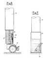
- the support ending 22 finally has a widened base 45 which can be variously shaped according to aesthetic preferences, and which can adapt to the coupling with a covering element 46, shown in figure 7, slotted over the adjustable foot in order to hide the functional components to improve its aesthetics.
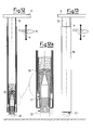
- Figures 8 and 9 show section views of a second embodiment of the expanding adjustment device 13' connected to a tubular end portion 12 of a height-adjustable leg 10. The following description is limited to the constituent elements which are different with respect to that which has already been illustrated.
- a bush 14', slotted over the tubular end 12 of the leg 10 and an elastic portion 25 of an adjustment sleeve 20' are equipped with matching engagement means, consisting of parallel grooves 47 and one or more parallel ribs 48.
- a contour follower element 23' is equipped with an extension cylinder 50 coupled at the bottom through a threaded connection 49. To carry out the fine height-adjustment operations of the leg it is, indeed possible to place the extension cylinder 50 in rotation, modifying the distance of the contour follower 23' from the floor (figures 8 and 9).
- the rapid adjustment is realised by applying an axial action in the desired direction X on the tubular portion 27 of the adjustment sleeve 20, causing its translation by one pitch at a time in the bush 14.
- the expansion stem 21 is disengaged from the elastic portion 25 of the sleeve 20, and therefore the respective matching engagement means, which hold the sleeve in position, are not force-fitted together with high friction, constituting a loose constraint.
- the rounded profile of the threads promotes the disengagement of crests and grooves of the threaded portions 18 and 26 which allows the progressive translation by one pitch. This is possible thanks to the presence of the cuts 31 in the wall 29, which promote its flexion in the direction of the vertical axis 30, as schematised by the arrows F.
- the expansion of the elastic portion 25 forces the threaded portion 26 against the threaded part 18 of the bush 14, creating a friction force which stably locks the expansion adjustment device 13 in the desired position.
- the fine adjustment is realised by intervening on the threaded portions 18 and 26 through rotation, in particular this is possible both in rest position and in working position with the leg loaded.
- the rapid adjustment is carried out by making the parallel ribs 48 of the elastic portion 25 translate by one pitch in the parallel grooves 47 of the bush 14'.
- the fine adjustment is carried out by rotating, through 50, the threaded connection 49 of the contour follower element 23'.
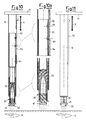
- Figures 10-13 show two further embodiments of a height-adjustable leg for a support surface, object of the present invention, respectively indicated with 10' and 10''.
- Figures 10 and 11 show a height-adjustable leg 10' for a support surface, equipped with a handle device 52 for applying the axial action according to the arrows X near to a support plane 11.
- the handle 52 is connected at one or more points, for example through dowels 53, to a telescopic tubular element 54 housed inside the tubular portion 12 of the leg.
- a free end of the element 54 engages with the elastic portion 25 of the adjustment sleeve 20 so as to allow the relative rotation, but to transfer the axial action applied on the handle 52 according to the arrows X.
- tubular portion 12 of the leg is equipped with a longitudinal fissure 55 which allows the sliding of the dowels 53 with respect to the leg itself.
- the fine adjustment is carried out by rotating the lower part of the foot, according to that which has already been described.
- a further embodiment, identified with 10'', of a height-adjustable leg, object of the present invention allows both of the adjustments to be realised without bending down.
- a tubular coating 56, bound at the bottom to the tubular portion 27 of the adjustment sleeve 20, is slotted over the tubular portion 12 of the leg.
- the binding for example a fixed joint, must transfer both the translational action and the rotary action applied by the user in any point of the tubular coating 56 to the sleeve.
- the friction which is created between the threads of the bush and expandable sleeve in the first embodiment of the adjustment device prevents the relative rotation following vibratory stress.
- the expansion of the elastic portion of the sleeve advantageously allows a possible recovery of the clearance between bush and adjustment sleeve.
- the shapes of the height-adjustable leg for a support surface, object of the present invention can be different to that which is shown as an example and not for limiting purposes in the drawings, just as the materials can also be different.
Landscapes
- Legs For Furniture In General (AREA)
- Ladders (AREA)
- Furniture Connections (AREA)
- Auxiliary Devices For Music (AREA)
- Chair Legs, Seat Parts, And Backrests (AREA)
- Special Chairs (AREA)
- Pallets (AREA)
Applications Claiming Priority (2)
| Application Number | Priority Date | Filing Date | Title |
|---|---|---|---|
| ITMI20012076 | 2001-10-09 | ||
| IT2001MI002076A ITMI20012076A1 (it) | 2001-10-09 | 2001-10-09 | Gamba regolabile in altezza per piano di appoggio |
Publications (2)
| Publication Number | Publication Date |
|---|---|
| EP1302133A1 true EP1302133A1 (de) | 2003-04-16 |
| EP1302133B1 EP1302133B1 (de) | 2005-06-08 |
Family
ID=11448484
Family Applications (1)
| Application Number | Title | Priority Date | Filing Date |
|---|---|---|---|
| EP02079049A Expired - Lifetime EP1302133B1 (de) | 2001-10-09 | 2002-10-01 | Höheneinstellbares Bein für eine Stützfläche |
Country Status (8)
| Country | Link |
|---|---|
| EP (1) | EP1302133B1 (de) |
| CN (1) | CN1250135C (de) |
| AT (1) | ATE297148T1 (de) |
| DE (1) | DE60204527T2 (de) |
| DK (1) | DK1302133T3 (de) |
| ES (1) | ES2243655T3 (de) |
| IT (1) | ITMI20012076A1 (de) |
| PT (1) | PT1302133E (de) |
Cited By (4)
| Publication number | Priority date | Publication date | Assignee | Title |
|---|---|---|---|---|
| EP1329176A1 (de) * | 2002-01-18 | 2003-07-23 | Ceka-Büromöbelwerke C. Krause und Sohn GmbH u. Co. KG | Tisch mit höhenverstellbarem Tischbein |
| KR101727120B1 (ko) | 2017-01-16 | 2017-04-17 | (주) 파트라 | 가구용 높이조절장치 |
| GB2566854A (en) * | 2018-12-20 | 2019-03-27 | Magrini Uk Ltd | Level-adjustable merchandise display unit |
| SE544482C2 (en) * | 2020-12-29 | 2022-06-14 | Per Hoeglunds Innovation Ab | Adjustable telescopic leg with locking mechanism comprising a resilitently loaded fixating member |
Families Citing this family (5)
| Publication number | Priority date | Publication date | Assignee | Title |
|---|---|---|---|---|
| CN102972985B (zh) * | 2012-10-30 | 2016-01-06 | 无锡鸿声铝业有限公司 | 一种支脚加长装置 |
| CN110236296A (zh) * | 2019-07-18 | 2019-09-17 | 立本集团有限公司 | 可调节高度的课桌 |
| DE102019122801B3 (de) * | 2019-08-26 | 2020-12-10 | Khs Gmbh | Maschinenfuß für Behälterbehandlungsmaschinen und Schutzhülse |
| CN118716303A (zh) * | 2024-08-09 | 2024-10-01 | 宁波智创渔具有限公司 | 一种便于调节的钓台调整脚 |
| TWI901536B (zh) * | 2025-03-21 | 2025-10-11 | 中材國際股份有限公司 | 具強化結構之支撐腳座 |
Citations (4)
| Publication number | Priority date | Publication date | Assignee | Title |
|---|---|---|---|---|
| US3224800A (en) * | 1963-05-13 | 1965-12-21 | Up Right Inc | Adjustable supporting leg |
| EP0645107A1 (de) * | 1993-09-28 | 1995-03-29 | METRO INDUSTRIES, Inc | Höhenverstellbarer Stützfuss |
| DE19825098C1 (de) * | 1998-06-05 | 1999-11-04 | Fennel Gmbh | Höhenversteller für Möbel oder dergleichen |
| US6027086A (en) * | 1997-03-10 | 2000-02-22 | Karl-Leo Heitlinger | Foot of a piece of furniture or support |
-
2001
- 2001-10-09 IT IT2001MI002076A patent/ITMI20012076A1/it unknown
-
2002
- 2002-10-01 DE DE60204527T patent/DE60204527T2/de not_active Expired - Lifetime
- 2002-10-01 DK DK02079049T patent/DK1302133T3/da active
- 2002-10-01 AT AT02079049T patent/ATE297148T1/de active
- 2002-10-01 EP EP02079049A patent/EP1302133B1/de not_active Expired - Lifetime
- 2002-10-01 ES ES02079049T patent/ES2243655T3/es not_active Expired - Lifetime
- 2002-10-01 PT PT02079049T patent/PT1302133E/pt unknown
- 2002-10-09 CN CN02144304.1A patent/CN1250135C/zh not_active Expired - Fee Related
Patent Citations (4)
| Publication number | Priority date | Publication date | Assignee | Title |
|---|---|---|---|---|
| US3224800A (en) * | 1963-05-13 | 1965-12-21 | Up Right Inc | Adjustable supporting leg |
| EP0645107A1 (de) * | 1993-09-28 | 1995-03-29 | METRO INDUSTRIES, Inc | Höhenverstellbarer Stützfuss |
| US6027086A (en) * | 1997-03-10 | 2000-02-22 | Karl-Leo Heitlinger | Foot of a piece of furniture or support |
| DE19825098C1 (de) * | 1998-06-05 | 1999-11-04 | Fennel Gmbh | Höhenversteller für Möbel oder dergleichen |
Cited By (8)
| Publication number | Priority date | Publication date | Assignee | Title |
|---|---|---|---|---|
| EP1329176A1 (de) * | 2002-01-18 | 2003-07-23 | Ceka-Büromöbelwerke C. Krause und Sohn GmbH u. Co. KG | Tisch mit höhenverstellbarem Tischbein |
| KR101727120B1 (ko) | 2017-01-16 | 2017-04-17 | (주) 파트라 | 가구용 높이조절장치 |
| GB2566854A (en) * | 2018-12-20 | 2019-03-27 | Magrini Uk Ltd | Level-adjustable merchandise display unit |
| GB2566854B (en) * | 2018-12-20 | 2020-02-26 | Magrini Uk Ltd | Level-adjustable merchandise display unit |
| SE544482C2 (en) * | 2020-12-29 | 2022-06-14 | Per Hoeglunds Innovation Ab | Adjustable telescopic leg with locking mechanism comprising a resilitently loaded fixating member |
| SE2051570A1 (en) * | 2020-12-29 | 2022-06-14 | Per Hoeglunds Innovation Ab | Adjustable telescopic leg with locking mechanism comprising a resilitently loaded fixating member |
| WO2022146223A1 (en) * | 2020-12-29 | 2022-07-07 | Per Höglunds Innovation Ab | Adjustable telescopic leg with locking mechanism |
| US12453412B2 (en) | 2020-12-29 | 2025-10-28 | Per Höglunds Innovation Ab | Adjustable telescopic leg with locking mechanism |
Also Published As
| Publication number | Publication date |
|---|---|
| CN1411765A (zh) | 2003-04-23 |
| DK1302133T3 (da) | 2005-10-10 |
| ITMI20012076A1 (it) | 2003-04-09 |
| EP1302133B1 (de) | 2005-06-08 |
| ES2243655T3 (es) | 2005-12-01 |
| CN1250135C (zh) | 2006-04-12 |
| DE60204527D1 (de) | 2005-07-14 |
| PT1302133E (pt) | 2005-10-31 |
| ATE297148T1 (de) | 2005-06-15 |
| DE60204527T2 (de) | 2006-04-20 |
Similar Documents
| Publication | Publication Date | Title |
|---|---|---|
| EP1302133B1 (de) | Höheneinstellbares Bein für eine Stützfläche | |
| US11304508B2 (en) | Height adjustable table and components of same | |
| US4627591A (en) | Adjustable legs for furniture and locking means for securing such adjustment | |
| CN101137308B (zh) | 用于坐具的支撑部件 | |
| JP2009534134A (ja) | 椅子用の機構 | |
| US9700138B2 (en) | Seating furniture product | |
| US6092771A (en) | Leg for a piece furniture with a telescopically movable portion | |
| US20140265512A1 (en) | Height adjustment mechanism suitable for a footring | |
| US20170151121A1 (en) | Walker | |
| CA2837363A1 (en) | Tilt mechanism for a chair and chair | |
| US4968094A (en) | Device for vertical adjustment of arm supports on chairs, especially wheel chairs | |
| KR20220169281A (ko) | 각도 조절이 가능한 발 받침대 | |
| US7530639B2 (en) | Chair with adjustable foot support | |
| US20200100971A1 (en) | Height adjustment delivery table | |
| US5881980A (en) | Leg assembly | |
| US5356203A (en) | Adjustable footrest | |
| GB2401097A (en) | Height adjustable and foldable highchair | |
| WO2003020078A3 (de) | Stuhl | |
| US20080060562A1 (en) | Extendable assembly for supporting sofa table | |
| US3287040A (en) | Telescopic assembly and locking means therefor | |
| AU2007278757A1 (en) | Furniture leg adjustment | |
| EP3315109A1 (de) | Gehilfe | |
| US7819482B2 (en) | Armrest/backrest support bracket for chairs, in particular office chairs | |
| KR200472055Y1 (ko) | 낚시용 의자의 다리구조 | |
| US12593911B2 (en) | Workbench with adjustable foot assembly |
Legal Events
| Date | Code | Title | Description |
|---|---|---|---|
| PUAI | Public reference made under article 153(3) epc to a published international application that has entered the european phase |
Free format text: ORIGINAL CODE: 0009012 |
|
| AK | Designated contracting states |
Designated state(s): AT BE BG CH CY CZ DE DK EE ES FI FR GB GR IE IT LI LU MC NL PT SE SK TR |
|
| AX | Request for extension of the european patent |
Extension state: AL LT LV MK RO SI |
|
| 17P | Request for examination filed |
Effective date: 20031002 |
|
| AKX | Designation fees paid |
Designated state(s): AT BE BG CH CY CZ DE DK EE ES FI FR GB GR IE IT LI LU MC NL PT SE SK TR |
|
| 17Q | First examination report despatched |
Effective date: 20040115 |
|
| GRAP | Despatch of communication of intention to grant a patent |
Free format text: ORIGINAL CODE: EPIDOSNIGR1 |
|
| GRAS | Grant fee paid |
Free format text: ORIGINAL CODE: EPIDOSNIGR3 |
|
| GRAA | (expected) grant |
Free format text: ORIGINAL CODE: 0009210 |
|
| AK | Designated contracting states |
Kind code of ref document: B1 Designated state(s): AT BE BG CH CY CZ DE DK EE ES FI FR GB GR IE IT LI LU MC NL PT SE SK TR |
|
| REG | Reference to a national code |
Ref country code: GB Ref legal event code: FG4D |
|
| REG | Reference to a national code |
Ref country code: CH Ref legal event code: EP |
|
| REF | Corresponds to: |
Ref document number: 60204527 Country of ref document: DE Date of ref document: 20050714 Kind code of ref document: P |
|
| REG | Reference to a national code |
Ref country code: IE Ref legal event code: FG4D |
|
| PG25 | Lapsed in a contracting state [announced via postgrant information from national office to epo] |
Ref country code: BG Free format text: LAPSE BECAUSE OF FAILURE TO SUBMIT A TRANSLATION OF THE DESCRIPTION OR TO PAY THE FEE WITHIN THE PRESCRIBED TIME-LIMIT Effective date: 20050908 |
|
| REG | Reference to a national code |
Ref country code: SE Ref legal event code: TRGR |
|
| REG | Reference to a national code |
Ref country code: CH Ref legal event code: NV Representative=s name: AMMANN PATENTANWAELTE AG BERN |
|
| PG25 | Lapsed in a contracting state [announced via postgrant information from national office to epo] |
Ref country code: CY Free format text: LAPSE BECAUSE OF FAILURE TO SUBMIT A TRANSLATION OF THE DESCRIPTION OR TO PAY THE FEE WITHIN THE PRESCRIBED TIME-LIMIT Effective date: 20051001 |
|
| PG25 | Lapsed in a contracting state [announced via postgrant information from national office to epo] |
Ref country code: IE Free format text: LAPSE BECAUSE OF NON-PAYMENT OF DUE FEES Effective date: 20051003 |
|
| REG | Reference to a national code |
Ref country code: DK Ref legal event code: T3 |
|
| PG25 | Lapsed in a contracting state [announced via postgrant information from national office to epo] |
Ref country code: LU Free format text: LAPSE BECAUSE OF NON-PAYMENT OF DUE FEES Effective date: 20051031 Ref country code: MC Free format text: LAPSE BECAUSE OF NON-PAYMENT OF DUE FEES Effective date: 20051031 |
|
| REG | Reference to a national code |
Ref country code: PT Ref legal event code: SC4A Effective date: 20050907 |
|
| REG | Reference to a national code |
Ref country code: GR Ref legal event code: EP Ref document number: 20050402712 Country of ref document: GR |
|
| REG | Reference to a national code |
Ref country code: ES Ref legal event code: FG2A Ref document number: 2243655 Country of ref document: ES Kind code of ref document: T3 |
|
| REG | Reference to a national code |
Ref country code: EE Ref legal event code: FG4A Ref document number: E000142 Country of ref document: EE Effective date: 20050901 |
|
| ET | Fr: translation filed | ||
| PLBE | No opposition filed within time limit |
Free format text: ORIGINAL CODE: 0009261 |
|
| STAA | Information on the status of an ep patent application or granted ep patent |
Free format text: STATUS: NO OPPOSITION FILED WITHIN TIME LIMIT |
|
| 26N | No opposition filed |
Effective date: 20060309 |
|
| REG | Reference to a national code |
Ref country code: IE Ref legal event code: MM4A |
|
| PGFP | Annual fee paid to national office [announced via postgrant information from national office to epo] |
Ref country code: AT Payment date: 20100921 Year of fee payment: 9 |
|
| PGFP | Annual fee paid to national office [announced via postgrant information from national office to epo] |
Ref country code: DE Payment date: 20101027 Year of fee payment: 9 |
|
| PGFP | Annual fee paid to national office [announced via postgrant information from national office to epo] |
Ref country code: GR Payment date: 20101026 Year of fee payment: 9 Ref country code: GB Payment date: 20101025 Year of fee payment: 9 |
|
| PGFP | Annual fee paid to national office [announced via postgrant information from national office to epo] |
Ref country code: EE Payment date: 20110922 Year of fee payment: 10 Ref country code: TR Payment date: 20110927 Year of fee payment: 10 Ref country code: PT Payment date: 20110921 Year of fee payment: 10 Ref country code: SK Payment date: 20110921 Year of fee payment: 10 Ref country code: CZ Payment date: 20110927 Year of fee payment: 10 |
|
| PGFP | Annual fee paid to national office [announced via postgrant information from national office to epo] |
Ref country code: FI Payment date: 20111027 Year of fee payment: 10 Ref country code: SE Payment date: 20111027 Year of fee payment: 10 Ref country code: NL Payment date: 20111028 Year of fee payment: 10 Ref country code: BE Payment date: 20111028 Year of fee payment: 10 Ref country code: CH Payment date: 20111025 Year of fee payment: 10 Ref country code: FR Payment date: 20111028 Year of fee payment: 10 Ref country code: DK Payment date: 20111026 Year of fee payment: 10 Ref country code: ES Payment date: 20111026 Year of fee payment: 10 |
|
| REG | Reference to a national code |
Ref country code: PT Ref legal event code: MM4A Free format text: LAPSE DUE TO NON-PAYMENT OF FEES Effective date: 20130401 |
|
| BERE | Be: lapsed |
Owner name: *LEONARDO S.R.L. Effective date: 20121031 |
|
| PG25 | Lapsed in a contracting state [announced via postgrant information from national office to epo] |
Ref country code: CZ Free format text: LAPSE BECAUSE OF NON-PAYMENT OF DUE FEES Effective date: 20121001 |
|
| REG | Reference to a national code |
Ref country code: NL Ref legal event code: V1 Effective date: 20130501 |
|
| REG | Reference to a national code |
Ref country code: CH Ref legal event code: PL |
|
| REG | Reference to a national code |
Ref country code: DK Ref legal event code: EBP |
|
| REG | Reference to a national code |
Ref country code: AT Ref legal event code: MM01 Ref document number: 297148 Country of ref document: AT Kind code of ref document: T Effective date: 20121001 |
|
| REG | Reference to a national code |
Ref country code: EE Ref legal event code: MM4A Ref document number: E000142 Country of ref document: EE Effective date: 20121031 |
|
| REG | Reference to a national code |
Ref country code: GR Ref legal event code: ML Ref document number: 20050402712 Country of ref document: GR Effective date: 20130508 |
|
| GBPC | Gb: european patent ceased through non-payment of renewal fee |
Effective date: 20121001 |
|
| REG | Reference to a national code |
Ref country code: SK Ref legal event code: MM4A Ref document number: E 230 Country of ref document: SK Effective date: 20121001 |
|
| REG | Reference to a national code |
Ref country code: FR Ref legal event code: ST Effective date: 20130628 |
|
| PG25 | Lapsed in a contracting state [announced via postgrant information from national office to epo] |
Ref country code: AT Free format text: LAPSE BECAUSE OF NON-PAYMENT OF DUE FEES Effective date: 20121001 Ref country code: LI Free format text: LAPSE BECAUSE OF NON-PAYMENT OF DUE FEES Effective date: 20121031 Ref country code: SE Free format text: LAPSE BECAUSE OF NON-PAYMENT OF DUE FEES Effective date: 20121002 Ref country code: DE Free format text: LAPSE BECAUSE OF NON-PAYMENT OF DUE FEES Effective date: 20130501 Ref country code: BE Free format text: LAPSE BECAUSE OF NON-PAYMENT OF DUE FEES Effective date: 20121031 Ref country code: EE Free format text: LAPSE BECAUSE OF NON-PAYMENT OF DUE FEES Effective date: 20121031 Ref country code: SK Free format text: LAPSE BECAUSE OF NON-PAYMENT OF DUE FEES Effective date: 20121001 Ref country code: GB Free format text: LAPSE BECAUSE OF NON-PAYMENT OF DUE FEES Effective date: 20121001 Ref country code: CH Free format text: LAPSE BECAUSE OF NON-PAYMENT OF DUE FEES Effective date: 20121031 |
|
| REG | Reference to a national code |
Ref country code: DE Ref legal event code: R119 Ref document number: 60204527 Country of ref document: DE Effective date: 20130501 |
|
| PG25 | Lapsed in a contracting state [announced via postgrant information from national office to epo] |
Ref country code: FR Free format text: LAPSE BECAUSE OF NON-PAYMENT OF DUE FEES Effective date: 20121031 Ref country code: PT Free format text: LAPSE BECAUSE OF NON-PAYMENT OF DUE FEES Effective date: 20130401 Ref country code: GR Free format text: LAPSE BECAUSE OF NON-PAYMENT OF DUE FEES Effective date: 20130508 Ref country code: FI Free format text: LAPSE BECAUSE OF NON-PAYMENT OF DUE FEES Effective date: 20121001 Ref country code: NL Free format text: LAPSE BECAUSE OF NON-PAYMENT OF DUE FEES Effective date: 20130501 |
|
| PG25 | Lapsed in a contracting state [announced via postgrant information from national office to epo] |
Ref country code: DK Free format text: LAPSE BECAUSE OF NON-PAYMENT OF DUE FEES Effective date: 20121031 |
|
| REG | Reference to a national code |
Ref country code: ES Ref legal event code: FD2A Effective date: 20140116 |
|
| PG25 | Lapsed in a contracting state [announced via postgrant information from national office to epo] |
Ref country code: ES Free format text: LAPSE BECAUSE OF NON-PAYMENT OF DUE FEES Effective date: 20121002 Ref country code: TR Free format text: LAPSE BECAUSE OF NON-PAYMENT OF DUE FEES Effective date: 20121001 |
|
| PGFP | Annual fee paid to national office [announced via postgrant information from national office to epo] |
Ref country code: IT Payment date: 20211021 Year of fee payment: 20 |