EP1302149B1 - Vorrichtung zum Schutzen des Motors eines Staubsaugers - Google Patents
Vorrichtung zum Schutzen des Motors eines Staubsaugers Download PDFInfo
- Publication number
- EP1302149B1 EP1302149B1 EP01127153A EP01127153A EP1302149B1 EP 1302149 B1 EP1302149 B1 EP 1302149B1 EP 01127153 A EP01127153 A EP 01127153A EP 01127153 A EP01127153 A EP 01127153A EP 1302149 B1 EP1302149 B1 EP 1302149B1
- Authority
- EP
- European Patent Office
- Prior art keywords
- motor housing
- dust
- motor
- pressure
- air
- Prior art date
- Legal status (The legal status is an assumption and is not a legal conclusion. Google has not performed a legal analysis and makes no representation as to the accuracy of the status listed.)
- Expired - Lifetime
Links
- 239000000463 material Substances 0.000 claims description 28
- 238000001914 filtration Methods 0.000 claims description 13
- 230000002159 abnormal effect Effects 0.000 claims description 4
- 239000000428 dust Substances 0.000 description 9
- 238000005192 partition Methods 0.000 description 6
- 238000000034 method Methods 0.000 description 3
- 230000007257 malfunction Effects 0.000 description 2
- 239000010893 paper waste Substances 0.000 description 2
- 238000011144 upstream manufacturing Methods 0.000 description 2
- 238000010276 construction Methods 0.000 description 1
- 230000003247 decreasing effect Effects 0.000 description 1
- 230000001419 dependent effect Effects 0.000 description 1
- 238000007599 discharging Methods 0.000 description 1
- 230000000694 effects Effects 0.000 description 1
- 238000005259 measurement Methods 0.000 description 1
- 238000012986 modification Methods 0.000 description 1
- 230000004048 modification Effects 0.000 description 1
- 238000000926 separation method Methods 0.000 description 1
- 229920003002 synthetic resin Polymers 0.000 description 1
- 239000000057 synthetic resin Substances 0.000 description 1
Images

Classifications
-
- A—HUMAN NECESSITIES
- A47—FURNITURE; DOMESTIC ARTICLES OR APPLIANCES; COFFEE MILLS; SPICE MILLS; SUCTION CLEANERS IN GENERAL
- A47L—DOMESTIC WASHING OR CLEANING; SUCTION CLEANERS IN GENERAL
- A47L9/00—Details or accessories of suction cleaners, e.g. mechanical means for controlling the suction or for effecting pulsating action; Storing devices specially adapted to suction cleaners or parts thereof; Carrying-vehicles specially adapted for suction cleaners
- A47L9/28—Installation of the electric equipment, e.g. adaptation or attachment to the suction cleaner; Controlling suction cleaners by electric means
- A47L9/2889—Safety or protection devices or systems, e.g. for prevention of motor over-heating or for protection of the user
-
- A—HUMAN NECESSITIES
- A47—FURNITURE; DOMESTIC ARTICLES OR APPLIANCES; COFFEE MILLS; SPICE MILLS; SUCTION CLEANERS IN GENERAL
- A47L—DOMESTIC WASHING OR CLEANING; SUCTION CLEANERS IN GENERAL
- A47L9/00—Details or accessories of suction cleaners, e.g. mechanical means for controlling the suction or for effecting pulsating action; Storing devices specially adapted to suction cleaners or parts thereof; Carrying-vehicles specially adapted for suction cleaners
- A47L9/10—Filters; Dust separators; Dust removal; Automatic exchange of filters
- A47L9/19—Means for monitoring filtering operation
-
- A—HUMAN NECESSITIES
- A47—FURNITURE; DOMESTIC ARTICLES OR APPLIANCES; COFFEE MILLS; SPICE MILLS; SUCTION CLEANERS IN GENERAL
- A47L—DOMESTIC WASHING OR CLEANING; SUCTION CLEANERS IN GENERAL
- A47L9/00—Details or accessories of suction cleaners, e.g. mechanical means for controlling the suction or for effecting pulsating action; Storing devices specially adapted to suction cleaners or parts thereof; Carrying-vehicles specially adapted for suction cleaners
- A47L9/22—Mountings for motor fan assemblies
-
- A—HUMAN NECESSITIES
- A47—FURNITURE; DOMESTIC ARTICLES OR APPLIANCES; COFFEE MILLS; SPICE MILLS; SUCTION CLEANERS IN GENERAL
- A47L—DOMESTIC WASHING OR CLEANING; SUCTION CLEANERS IN GENERAL
- A47L9/00—Details or accessories of suction cleaners, e.g. mechanical means for controlling the suction or for effecting pulsating action; Storing devices specially adapted to suction cleaners or parts thereof; Carrying-vehicles specially adapted for suction cleaners
- A47L9/28—Installation of the electric equipment, e.g. adaptation or attachment to the suction cleaner; Controlling suction cleaners by electric means
- A47L9/2805—Parameters or conditions being sensed
- A47L9/2821—Pressure, vacuum level or airflow
Definitions
- the present invention relates to a vacuum cleaner, and more particularly, to a safety device by which a driving motor for generating suction force in a vacuum cleaner cannot be overloaded.
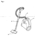
- a vacuum cleaner is generally constructed to comprise a main body 2, a connecting hose 4 connected to the main body 2, an extension tube 6 connected to the connecting hose 4, and a suction nozzle 8 mounted to a lower end of the extension tube 6.
- a driving motor for generating suction force and a filtering device for filtering air containing foreign materials to be introduced are included in the main body 2.
- the connecting hose 4 which is manufactured in the form of a pipe made of flexible material, causes the main body 2 to be connected to the extension tube 6.
- the extension tube 6 is generally constructed to be extendable and contractible. Further, a handle gripped by a user is formed at an upper portion of the extension tube.
- the suction force generated from the main body 2 is transferred to the suction nozzle 8 via the connecting hose 4 and the extension tube 6.
- the suction nozzle 8 since the suction nozzle 8 is usually used in a state where it is in contact with a surface to be cleaned, the foreign materials such as dusts on a room floor is introduced into the main body through the suction nozzle 8 together with the air.
- the air containing the foreign material introduced as such is introduced into the main body through the extension tube 6 and the connecting hose 4, and then is filtered.
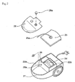
- FIG. 2 shows an interior structure of the main body 2 of the cleaner in a state where an upper casing of the main body 2 is opened.
- a dust-collecting chamber 22a into which a dust-collecting bag such as a paper bag is inserted is provided within a lower casing 21 constructing a lower portion of the main body 2.
- the dust-collecting chamber 22a is divided by a partition 26, while a chamber 22b for accommodating the motor (hereinafter, referred to as a "motor chamber”) is formed at the other side of the partition 26.
- a motor housing 24 in which the motor for generating the suction force is mounted is installed within the motor chamber 22b.
- a motor cover 25 for opening and closing an upper portion of the motor housing 24 is provided with a connecting tube 25a that communicates with the motor chamber 22b located below the motor cover.
- a dust-collecting bag (not shown) for allowing only the air, out of the air containing the introduced foreign materials, to be discharged to the outside is installed within the dust-collecting chamber 22a.
- a cover 28 in which a damper 28a is mounted is installed at an upper portion of the dust-collecting chamber 22a.
- the damper 28a has a construction that the damper is opened when pressure within the dust-collecting chamber 22a becomes lower than the atmosphere pressure, so that air outside the main body of the cleaner can be introduced into the dust-collecting chamber 22a.
- the structure of the damper 28a itself is well known, and thus, detailed description thereof will be omitted.
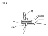
- the connecting tube 25a connected to the motor cover 25 is connected to a vent hole 26a formed in the partition 26, and a pressure switch 27 for sensing pressure within the dust-collecting chamber 22a is connected to an end of the connecting tube 25a.
- the pressure switch 27 is formed through the vent hole 26a so that it can sense the pressure within the dust-collecting chamber 22a.
- the suction pressure generated when the motor installed within the motor housing 24 starts to operate is transferred to the suction nozzle 8, and consequently, the foreign materials such as dusts remaining on the room floor are introduced into the main body 2 through the suction nozzle 8. Further, only the air out of the air containing the foreign materials, which has been introduced into the dust-collecting bag inserted into the dust-collecting chamber within the main body, flows from the dust-collecting bag. Thus, the foreign materials such as dusts are gradually collected within the dust-collecting bag.
- the air flowing from the inside to the outside of the dust-collecting bag passes through the interior of the motor housing 24, and is discharged to the outside of the cleaner.
- the reason why the air passes through the interior of the motor housing 24 is that the air should cool down the motor from which heat is generated during its operation.
- the pressure within the dust-collecting chamber 22a is lowered. That is, the pressure within the dust-collecting chamber 22a is lowered, because the motor installed within the motor housing 24 incessantly performs its own discharge operation whereas a small quantity of the air is introduced into the dust-collecting chamber 22a.
- the motor installed within the motor housing 24 is substantially overloaded. That is, this is because the motor discharges the air within the dust-collecting chamber while operating in such a state where the air cannot be normally introduced into the dust-collecting chamber 22a due to the foreign materials filled into the dust-collecting bag inserted into dust-collecting chamber.
- an overload is not preferable since it exerts a critical influence on a function of the cleaner.
- the pressure switch 27 mounted to sense the pressure within dust-collecting chamber 22a through the vent hole 26a in the partition 26 can sense reduction of the pressure within the dust-collecting chamber. Further, based on the pressure sensed by the pressure switch 27, alarm lights or sounds can be produced to inform the user that the cleaner is in an abnormal state. Thus, the user can take measures such exchange of the dust-collecting bag.
- the motor installed within the motor housing is continuously overloaded.
- the damper 28a mounted on the cover 28 starts to operate. That is, if the pressure within the dust-collecting chamber 22a is greatly lower than the outside pressure, the damper 28a is opened and the air outside the main body of the cleaner is then introduced into the dust-collecting chamber 22a so that the motor is prevented from being overloaded.
- the aforementioned damper 28a and pressure switch 27 are parts for eventually preventing the motor from being overloaded. According to the prior art mentioned above, however, the pressure switch 27 senses merely the pressure within the dust-collecting chamber 22a, and moreover, it measures the pressure through the connecting tube 25a. Thus, there is likelihood that any error in measurement of the pressure can be produced. Consequently, the pressure cannot be accurately measured.
- the aforementioned conventional constitution is not substantially simple and requires the other components such as tubes.
- the number of parts is increased and fabricating processes become complicated.
- US-A-6167588 discloses a vacuum cleaner with filter clogging indicating means.
- the vacuum cleaner comprises a bleed valve upstream of a pre-motor filter to allow air to be bled into an airflow path in the event of a blockage occurring upstream of the bleed valve.
- the arrangement is such that the bleed air is introduced into a cyclonic dust separator in order to maintain an adequate airflow to effect separation. Since the air from the bleed valve is not directly bled into the motor housing, if the cyclonic dust separator or the pre-motor filter is blocked, the introduction of air through the bleed valve might not be sufficient to protect the motor from damage.
- US-A-4597131 describes a vacuum cleaner that has an electrical pressure switch mounted to a part of a motor fan unit.
- An object of the present invention is to provide a vacuum cleaner comprising a device for protecting a motor in the vacuum cleaner by which it can be more accurately sensed whether the motor is overloaded and a sufficient quantity of air can be directly introduced into a motor housing when the motor is overloaded.
- Another aspect of the present invention is to provide a vacuum cleaner with a simplified device for protecting the motor in the vacuum cleaner.
- a vacuum cleaner comprising a device for protecting a motor as defined in claim 1.
- Preferred embodiments are defined in the dependent claims.
- overload imposed on the motor can be sensitively and accurately controlled since external air can be directly introduced into the motor housing through the damper when the motor is overloaded.
- the pressure switch of a preferred embodiment can directly sense the pressure within the motor housing. Therefore, there is an advantage in that the motor can be rapidly and sufficiently protected against its overload.
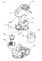
- a main body of the vacuum cleaner comprises an upper casing 110 and a lower casing 170 that construct upper and lower portions of the main body, respectively. Parts of the vacuum cleaner to be described later are included in the upper casing 110 and the lower casing 170.
- a motor housing 160 and a dust-collecting unit 140 are installed at front and rear portions on the lower casing 170, respectively.
- the dust-collecting unit 140 is adapted for filtering out foreign materials from air, in which the foreign materials introduced into the main body of the cleaner are contained, and for discharging the filtered air to the outside through the motor housing 160.
- any kinds of the dust-collecting casings can be employed in the present invention if the foreign materials can be filtered out from the air introduced into the main body of the cleaner by the dust-collecting casing.
- the dust-collecting unit 140 may be constructed such that both a primary dust collection performed in a cyclone mode and a secondary dust collection performed by the filter can be simultaneously made.
- the motor housing 160 including a driving motor 150 therein is installed at a front portion of the lower casing 170.
- the driving motor 150 included in the motor housing 160 is a part for substantially generating suction force within the vacuum cleaner itself.
- the motor housing 160 is formed with an upper portion thereof opened upwardly, and the driving motor 150 is included therein.
- the air containing the foreign materials is introduced into the main body of the cleaner through an inlet 146. Further, the inlet 146 is fitted into an inlet portion 112 of the upper casing 110 shown in FIG. 4 .
- the air which has been introduced into the dust-collecting unit 140 through the inlet 146 and the foreign materials have been filtered out therefrom as mentioned above, is discharged through the outlet 142.
- the filtered air is guided into the motor housing 160 through a connecting duct 145. Since an upper portion of the motor housing 160 is opened upwardly, the air introduced through the upper portion of the housing cools down the driving motor 150 while going through the motor, and then is discharged through one side of the motor housing 160.
- An intermediate cover 120 is mounted over the dust-collecting unit 140 and the motor housing 160.
- the intermediate cover 120 is a part mounted to simultaneously cover upper portions of the motor housing 160 and the dust-collecting unit 140.
- the intermediate cover 120 is integrally formed with a first cover portion or dust-collecting casing cover portion 122 for covering the dust-collecting casing and a second cover portion or motor housing cover portion 124 for covering the motor housing.
- the dust-collecting casing cover portion 122 is positioned over the dust-collecting unit 140, and the motor housing cover portion 124 is formed to be stepped with respect to the dust-collecting casing cover portion 122 and comes into close contact with the upper portion of the motor housing 160. That is, the motor housing cover portion 124 for covering the motor housing 160 is mounted to be in close contact with the opened upper portion of the motor housing 160.
- the dust-collecting casing covering portion 122 of the intermediate cover 120 is formed with an outlet hole 123 communicating with the outlet 142 of the dust-collecting unit 140. Further, the motor housing cover portion 124 of the cover 120 is formed with an inlet hole 125 for the motor housing, through which the air discharged from the outlet hole 123 is again introduced into the motor housing 160 via the connecting duct 145.
- the motor housing 160 is substantially covered with and is hermetically sealed by the motor housing cover portion 124 that has come into close contact with the opened upper portion of the motor housing 160. Further, it is constructed such that the air can be introduced, through the inlet hole 125 of the motor housing, into such a sealed space of the motor housing 160.
- the motor housing cover portion 124 for covering the motor housing is formed with a damper mounting hole 126 and a switch mounting hole 128 which communicate with the motor housing.
- a damper A is installed in the damper mounting hole 126.
- the damper A is constructed such that it can be opened by means of pressure difference between the locations over and below the motor housing cover portion 124 of the intermediate cover 120. That is, the damper A is opened when the pressure over the intermediate cover 120 is higher than the pressure below the intermediate cover, and thus, the air is introduced below the intermediate cover 120 (i.e., into the motor housing 160).
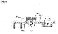
- the damper A has been already well known in the art, the constitution thereof will be briefly described with reference to FIG. 6 .
- the damper A comprises a casing Aa with apertures formed at upper and lower portions thereof, a shield plate Ab mounted to the upper portion of the casing, and a spring Ac for urging the shield plate Ab upwardly to hermetically seal the upper aperture.
- the spring Ac is compressed by means of the pressure difference, and then, the shield plate Ab moves downwardly.
- the air over the intermediate cover 120 can be introduced into the damper through the upper aperture, and then, be introduced into the motor housing 160 through the lower aperture.
- a pressure switch or sensor B is mounted to the switch mounting hole 128 of the intermediate cover 120.
- the pressure switch B is generally used for measuring the pressure within the motor housing 160 located below the intermediate cover 120. Since the constitution of the pressure sensor itself is well known in the art, the detailed description thereof will be omitted.
- the suction force is generated in the vacuum cleaner.
- the air mixed with the foreign materials for example, the air in which the foreign materials from the room floor etc. is contained, is introduced into the cleaner through the inlet 146 fitted into the inlet portion 112 formed on the upper casing 110.
- the air introduced through the inlet 146 is also introduced into the dust-collecting unit 140 in which the foreign materials contained in the air are in turn completely filtered out.
- the foreign materials contained in the air are completely filtered out in the process of the primary dust collection performed in the cyclone mode and the secondary dust collection performed by the filter.
- the air discharged from the dust-collecting unit 140 is introduced into motor housing 160 through the connecting duct 145.
- the air introduced into the motor housing 160 cools down the motor that radiates heat during its operation, and then, is discharged to the outside through the side of the motor housing.
- any problems may occur in the interior of the dust-collecting unit 140.
- the driving motor 150 is overloaded. That is, although the driving motor 150 normally operates, the air cannot be normally introduced from the dust-collecting unit 140 into the motor housing 160. Thus, the driving motor 150 is overloaded.
- the pressure within the space defined by the second covering portion 124 of the intermediate cover 120 and the motor housing 160 is lowered.
- the pressure switch B firstly senses reduction of the pressure. Then, in accordance with a signal corresponding to the pressure sensed by the pressure switch B, either a buzzer or a light emitting means such as LED informs the user that the vacuum cleaner is in an abnormal state. Further, according to the present invention, since the pressure switch B is directly installed onto the motor housing cover portion 124 for covering the motor housing 160, the pressure reduction within the motor housing 160 can be sensed in the most sensitive and accurate manner.
- the vacuum cleaner can normally operate again.
- the load imposed on the driving motor 150 of the vacuum cleaner is further increased. If the load is increased, critical damage by which the driving motor 150 cannot perform its own normal operation may be produce.
- the damper A is constructed to be opened by means of the pressure difference between the locations over the intermediate cover 120 and within the motor housing 160, which is generated due to the pressure reduction in the motor housing 160. That is, as shown in FIG. 6 , the spring Ac is compressed by means of the pressure difference between the locations over the intermediate cover 120 and within the motor housing 160. Then, the shield plate Ab moves downwardly and the upper aperture of the damper A is opened. Consequently, the external air is introduced into the motor housing 160. Since the external air is introduced into the motor housing as such, the overload imposed on the driving motor 150 can be removed.
- the overload imposed on the motor can be sufficiently removed. It can be most sensitively determined by sensing the pressure within the motor housing 160 whether the driving motor 150 is overloaded. Further, the overload imposed on the driving motor 150 can be most rapidly and sufficiently solved by directly introducing the external air into the motor housing 160.
- the overload imposed on the driving motor can be sensed most sensitively and accurately.
- the overload can be rapidly alarmed to and solved by the user. Accordingly, an advantage that reliability of the products can be further improved is expected.
- the dust-collecting unit 140 has been used as an example of a filtering means for removing the foreign materials from the air in which the foreign materials introduced into the main body of the vacuum cleaner are contained.
- the filtering device for filtering out the foreign materials cannot be limited to the aforementioned dust-collecting unit 140. That is, it is apparent that the other means for filtering out the foreign materials can be installed instead of the dust-collecting unit 140.
- the dust-collecting bag made of paper may be employed in the present invention.
Landscapes
- Engineering & Computer Science (AREA)
- Mechanical Engineering (AREA)
- Electric Vacuum Cleaner (AREA)
- Electric Suction Cleaners (AREA)
Claims (4)
- Staubsauger mit einer Vorrichtung zum Schützen eines Antriebsmotors (150), mit:einem unteren Gehäuse (170) zum Bilden eines unteren Abschnitts eines Hauptkörpers des Staubsaugers,einem Motorgehäuse (160), das in dem unteren Gehäuse (170) installiert ist und den Antriebsmotor (150) darin aufweist, und dessen oberer Abschnitt nach oben hin geöffnet ist,einem Filtermittel (140), das an dem unteren Gehäuse (170) installiert ist, zum Herausfiltern von Fremdstoffen aus eingeleiteter Luft, undeiner Zwischenabdeckung (120), die integral mit einem ersten Abdeckabschnitt (122) ausgebildet ist, welcher an einem oberen Abschnitt des Filtermittels (140) positioniert ist, und einem zweiten Abdeckabschnitt (124) zum Abdecken des oberen Abschnitts des Motorgehäuses (160),wobei eine Absperrvorrichtung (A) an dem zweiten Abdeckabschnitt (124) der Zwischenabdeckung (120) installiert ist, und die Absperrvorrichtung (A) Außenluft in das Motorgehäuse (160) einleiten kann, wenn der Druck in dem Motorgehäuse (160) unter einen vorbestimmten Druckwert sinkt.
- Staubsauger nach Anspruch 1, wobei
ein Druckschalter (B) zum Abtasten von Druck innerhalb des Motorgehäuses (160) direkt an dem zweiten Abdeckabschnitt (124) der Zwischenabdeckung (120) installiert ist, und
ein Signaltongeber oder ein Lichtemissionsmittel zum Informieren eines Benutzers entsprechend einem Signal, das dem von dem Druckschalter (B) abgetasteten Druck entspricht und einen anormalen Zustand darstellt, vorgesehen ist. - Staubsauger nach Anspruch 1 oder 2, mit einem Kanal (145), der das Filtermittel (140) mit dem Motorgehäuse (160) zum Einleiten von aus dem Filtermittel (140) ausgestoßener Luft in das Motorgehäuse (160), um den Antriebsmotor (150) zu kühlen, verbindet.
- Staubsauger nach Anspruch 1, 2 oder 3, mit einem Einlaß (146), durch den Luft in das Filtermittel (140) eingeleitet werden kann.
Applications Claiming Priority (2)
| Application Number | Priority Date | Filing Date | Title |
|---|---|---|---|
| KR10-2001-0063270A KR100432730B1 (ko) | 2001-10-15 | 2001-10-15 | 진공청소기의 모터 보호장치 |
| KR2001063270 | 2001-10-15 |
Publications (3)
| Publication Number | Publication Date |
|---|---|
| EP1302149A2 EP1302149A2 (de) | 2003-04-16 |
| EP1302149A3 EP1302149A3 (de) | 2006-07-12 |
| EP1302149B1 true EP1302149B1 (de) | 2008-05-07 |
Family
ID=19715111
Family Applications (1)
| Application Number | Title | Priority Date | Filing Date |
|---|---|---|---|
| EP01127153A Expired - Lifetime EP1302149B1 (de) | 2001-10-15 | 2001-11-15 | Vorrichtung zum Schutzen des Motors eines Staubsaugers |
Country Status (8)
| Country | Link |
|---|---|
| US (2) | US6651294B2 (de) |
| EP (1) | EP1302149B1 (de) |
| JP (1) | JP3637015B2 (de) |
| KR (1) | KR100432730B1 (de) |
| CN (1) | CN1236720C (de) |
| AU (1) | AU755814B1 (de) |
| DE (1) | DE60133900D1 (de) |
| RU (1) | RU2197167C1 (de) |
Families Citing this family (24)
| Publication number | Priority date | Publication date | Assignee | Title |
|---|---|---|---|---|
| EP1491127B1 (de) * | 2003-06-26 | 2012-10-17 | Black & Decker Inc. | Staubsauger |
| US7712182B2 (en) * | 2003-07-25 | 2010-05-11 | Milwaukee Electric Tool Corporation | Air flow-producing device, such as a vacuum cleaner or a blower |
| KR20050026163A (ko) * | 2003-09-09 | 2005-03-15 | 삼성광주전자 주식회사 | 진공청소기의 모터 과부하 방지장치 |
| KR20060009981A (ko) * | 2004-07-27 | 2006-02-02 | 엘지전자 주식회사 | 진공청소기 |
| DE102004040985A1 (de) * | 2004-08-24 | 2006-03-02 | BSH Bosch und Siemens Hausgeräte GmbH | Staubsauger mit angeformtem Ventilgehäuse |
| KR20060037980A (ko) * | 2004-10-29 | 2006-05-03 | 엘지전자 주식회사 | 진공청소기의 본체 |
| KR100717441B1 (ko) * | 2005-05-26 | 2007-05-14 | 엘지전자 주식회사 | 진공청소기의 본체 |
| KR100676320B1 (ko) | 2005-05-30 | 2007-01-30 | 삼성광주전자 주식회사 | 진공청소기의 모터보호장치 |
| KR20070010279A (ko) * | 2005-07-18 | 2007-01-24 | 엘지전자 주식회사 | 진공청소기의 집진유니트 |
| DE102005045544A1 (de) * | 2005-09-23 | 2007-03-29 | Vorwerk & Co. Interholding Gmbh | Verfahren zum Generieren eines Signals zum Filterbeutelwechsel sowie Staubsauger mit einem Sauggebläse |
| KR100710392B1 (ko) | 2005-10-05 | 2007-04-24 | 엘지전자 주식회사 | 진공청소기 |
| US8146201B2 (en) * | 2006-12-12 | 2012-04-03 | G.B.D. Corp. | Surface cleaning apparatus |
| US9301666B2 (en) | 2006-12-12 | 2016-04-05 | Omachron Intellectual Property Inc. | Surface cleaning apparatus |
| US9192269B2 (en) | 2006-12-15 | 2015-11-24 | Omachron Intellectual Property Inc. | Surface cleaning apparatus |
| KR100820064B1 (ko) * | 2006-12-20 | 2008-04-11 | 주식회사 대우일렉트로닉스 | 진공도 측정장치 및 진공청소기 |
| KR100820063B1 (ko) * | 2006-12-20 | 2008-04-11 | 주식회사 대우일렉트로닉스 | 진공도 측정장치 및 진공청소기 |
| US20090183337A1 (en) * | 2008-01-17 | 2009-07-23 | Davis Ronald E | Vacuum cleaner equipped with motor exhaust system |
| KR101534060B1 (ko) * | 2009-01-19 | 2015-07-16 | 삼성전자주식회사 | 댐퍼 조립체, 이를 구비한 진공청소기 및 이를 이용한 모터보호 및 먼지비움시기 알림방법 |
| US8887349B2 (en) * | 2009-04-16 | 2014-11-18 | Lg Electronics Inc. | Vacuum cleaner |
| KR20110004519A (ko) | 2009-07-08 | 2011-01-14 | 삼성광주전자 주식회사 | 진공청소기의 팬모터유닛 및 진공청소기 |
| KR101136592B1 (ko) * | 2009-12-30 | 2012-04-18 | 엘지전자 주식회사 | 진공 청소기의 이물 막힘 감지구조 |
| DE102010030222B3 (de) * | 2010-06-17 | 2011-07-28 | BSH Bosch und Siemens Hausgeräte GmbH, 81739 | Staubsauger mit Nebenluftventil |
| US20140237768A1 (en) | 2013-02-28 | 2014-08-28 | G.B.D. Corp. | Surface cleaning apparatus |
| JP6078791B2 (ja) * | 2013-05-21 | 2017-02-15 | パナソニックIpマネジメント株式会社 | 電気掃除機 |
Family Cites Families (35)
| Publication number | Priority date | Publication date | Assignee | Title |
|---|---|---|---|---|
| US2439182A (en) * | 1943-09-27 | 1948-04-06 | Air Way Electric Appl Corp | Blower control device for suction cleaners |
| US3089177A (en) * | 1960-02-05 | 1963-05-14 | Electrolux Ab | Vacuum cleaner |
| US3170184A (en) * | 1960-06-30 | 1965-02-23 | Sunbeam Corp | Vacuum cleaner |
| US3101889A (en) * | 1961-06-27 | 1963-08-27 | Gen Electric | Resilient mounting for motor and fan unit |
| US3651536A (en) * | 1970-01-08 | 1972-03-28 | James J Bolzan Jr | Canister vacuum cleaner with retractable hose |
| US3636681A (en) * | 1970-03-20 | 1972-01-25 | Singer Co | Vacuum cleaner filter assembly |
| US3871847A (en) * | 1974-01-16 | 1975-03-18 | Whirlpool Co | Vacuum cleaner filter |
| US3932911A (en) * | 1974-01-16 | 1976-01-20 | Whirlpool Corporation | Structure for mounting air moving means in a vacuum cleaner |
| US4597131A (en) * | 1984-07-16 | 1986-07-01 | Whirlpool Corporation | Mounting for motor-fan unit |
| US4733431A (en) * | 1986-12-09 | 1988-03-29 | Whirlpool Corporation | Vacuum cleaner with performance monitoring system |
| SE461189B (sv) * | 1988-05-25 | 1990-01-22 | Electrolux Ab | Dammsugare |
| GB2225220B (en) * | 1988-10-19 | 1992-08-26 | Hoover Plc | Suction cleaner |
| FR2641460B1 (fr) * | 1989-01-12 | 1993-04-09 | Moulinex Sa | Procede d'assemblage des elements d'un boitier d'aspirateur et boitier assemble selon un tel procede |
| SU1687254A1 (ru) * | 1989-06-19 | 1991-10-30 | Киевское научно-производственное объединение "Веста" | Устройство дл определени запыленности фильтров пылесоса |
| EP0458057B1 (de) * | 1990-04-16 | 1995-02-01 | Hitachi, Ltd. | Verfahren zum Betreiben eines Staubsaugers |
| DE69116016T2 (de) * | 1990-07-18 | 1996-09-05 | Sanyo Electric Co | Staubsauger mit, nach Bodenart drehzahlregelbarem Gebläsemotor |
| RU2004185C1 (ru) * | 1991-07-10 | 1993-12-15 | Пермский научно-исследовательский технологический институт | Индикатор степени заполнени пылесборника пылесоса |
| KR930001867A (ko) * | 1991-07-26 | 1993-02-22 | 배순훈 | 저소음 진공청소기 |
| JPH0549581A (ja) * | 1991-08-21 | 1993-03-02 | Matsushita Electric Ind Co Ltd | 電気掃除機 |
| US5513417A (en) * | 1993-07-19 | 1996-05-07 | Samsung Electronics Co., Ltd. | Silencing device for vacuum cleaner |
| GB2297243A (en) * | 1995-01-27 | 1996-07-31 | Notetry Ltd | Vacuum cleaner for use on stairs |
| KR200144881Y1 (ko) * | 1995-07-05 | 1999-06-15 | 최진호 | 진공청소기의 집진표시겸용 과부하방지장치 |
| KR100443091B1 (ko) * | 1995-08-25 | 2004-11-06 | 코닌클리케 필립스 일렉트로닉스 엔.브이. | 전기브러시의조작모드에따라파워가제어되는진공청소기 |
| SE9503753D0 (sv) * | 1995-10-25 | 1995-10-25 | Electrolux Ab | Anordning vid en dammsugare |
| DE69707415T2 (de) * | 1996-06-28 | 2002-06-06 | Koninklijke Philips Electronics N.V., Eindhoven | Staubsaugergehäuse mit minimierter anzahl von richtungen zum lösen aus einer gussform |
| GB2320419B (en) * | 1996-12-20 | 2000-08-16 | Notetry Ltd | Improved vacuum cleaner |
| JPH119526A (ja) * | 1997-06-24 | 1999-01-19 | Tec Corp | 電気掃除機 |
| KR100240764B1 (ko) * | 1997-12-10 | 2000-04-01 | 전주범 | 진공청소기의 압력스위치 |
| US6026539A (en) * | 1998-03-04 | 2000-02-22 | Bissell Homecare, Inc. | Upright vacuum cleaner with full bag and clogged filter indicators thereon |
| KR19990074970A (ko) * | 1998-03-16 | 1999-10-05 | 배길성 | 진공청소기의 모터보호용 먼지봉투교환표시장치 |
| KR20000000629U (ko) * | 1998-06-13 | 2000-01-15 | 배길성 | 진공청소기의 본체 |
| US6484350B2 (en) * | 1999-12-08 | 2002-11-26 | Shell Electric Mfg. (Holdings) Co. Ltd. | Bagless canister vacuum cleaner |
| KR100629737B1 (ko) * | 2000-12-29 | 2006-09-29 | 엘지전자 주식회사 | 진공청소기용 먼지필터의 청소구조 |
| KR20020094688A (ko) * | 2001-06-13 | 2002-12-18 | 주식회사 엘지이아이 | 진공청소기의 댐퍼 |
| US6618898B2 (en) * | 2001-09-05 | 2003-09-16 | Charles Wayne Tingle | Animal waste vacuum |
-
2001
- 2001-10-15 KR KR10-2001-0063270A patent/KR100432730B1/ko not_active Expired - Fee Related
- 2001-11-12 AU AU89384/01A patent/AU755814B1/en not_active Ceased
- 2001-11-15 EP EP01127153A patent/EP1302149B1/de not_active Expired - Lifetime
- 2001-11-15 DE DE60133900T patent/DE60133900D1/de not_active Expired - Fee Related
- 2001-11-21 US US09/989,460 patent/US6651294B2/en not_active Expired - Fee Related
- 2001-11-22 JP JP2001357730A patent/JP3637015B2/ja not_active Expired - Fee Related
- 2001-11-23 RU RU2001131703/12A patent/RU2197167C1/ru not_active IP Right Cessation
- 2001-11-26 CN CNB011396202A patent/CN1236720C/zh not_active Expired - Fee Related
-
2003
- 2003-09-12 US US10/660,776 patent/US7278180B2/en not_active Expired - Fee Related
Also Published As
| Publication number | Publication date |
|---|---|
| JP2003116748A (ja) | 2003-04-22 |
| KR100432730B1 (ko) | 2004-05-24 |
| US7278180B2 (en) | 2007-10-09 |
| JP3637015B2 (ja) | 2005-04-06 |
| AU755814B1 (en) | 2002-12-19 |
| CN1236720C (zh) | 2006-01-18 |
| US6651294B2 (en) | 2003-11-25 |
| EP1302149A3 (de) | 2006-07-12 |
| RU2197167C1 (ru) | 2003-01-27 |
| DE60133900D1 (de) | 2008-06-19 |
| CN1411779A (zh) | 2003-04-23 |
| EP1302149A2 (de) | 2003-04-16 |
| US20040049880A1 (en) | 2004-03-18 |
| US20030070254A1 (en) | 2003-04-17 |
| KR20030031575A (ko) | 2003-04-23 |
Similar Documents
| Publication | Publication Date | Title |
|---|---|---|
| EP1302149B1 (de) | Vorrichtung zum Schutzen des Motors eines Staubsaugers | |
| US4124916A (en) | Vacuum cleaner condition indicator and safety device | |
| EP0951230B1 (de) | Staubsauger mit einer vorrichtung zum anzeigen der verstopfung des filters | |
| US6231649B1 (en) | Apparatus for separating particles from a fluid and a valve for introducing bled fluid to a mainstream fluid | |
| US6026539A (en) | Upright vacuum cleaner with full bag and clogged filter indicators thereon | |
| EP1674009B1 (de) | Staubsauger | |
| US4733431A (en) | Vacuum cleaner with performance monitoring system | |
| US7931716B2 (en) | Handheld cleaning appliance | |
| AU690369B2 (en) | A vacuum cleaner and a filter assembly therefor | |
| CA1063886A (en) | Vacuum cleaner filter bag condition indicator | |
| EP1703832A1 (de) | Filtersensor und anzeige für staubsauger | |
| GB2372431A (en) | Air bleed valve arrangement in a vacuum cleaner | |
| US7462210B2 (en) | Dust collecting unit for vacuum cleaner | |
| EP1741376B1 (de) | Staubsauger mit System zur Feststellung des Fehlens des Filters | |
| HK1019846B (en) | Apparatus for separating particles from a fluid flow and a valve for introducing bled fluid to a mainstream fluid |
Legal Events
| Date | Code | Title | Description |
|---|---|---|---|
| PUAI | Public reference made under article 153(3) epc to a published international application that has entered the european phase |
Free format text: ORIGINAL CODE: 0009012 |
|
| 17P | Request for examination filed |
Effective date: 20011115 |
|
| AK | Designated contracting states |
Designated state(s): AT BE CH CY DE DK ES FI FR GB GR IE IT LI LU MC NL PT SE TR |
|
| AX | Request for extension of the european patent |
Extension state: AL LT LV MK RO SI |
|
| PUAL | Search report despatched |
Free format text: ORIGINAL CODE: 0009013 |
|
| AK | Designated contracting states |
Kind code of ref document: A3 Designated state(s): AT BE CH CY DE DK ES FI FR GB GR IE IT LI LU MC NL PT SE TR |
|
| AX | Request for extension of the european patent |
Extension state: AL LT LV MK RO SI |
|
| 17Q | First examination report despatched |
Effective date: 20060816 |
|
| AKX | Designation fees paid |
Designated state(s): DE FR GB IT SE |
|
| 17Q | First examination report despatched |
Effective date: 20060816 |
|
| GRAP | Despatch of communication of intention to grant a patent |
Free format text: ORIGINAL CODE: EPIDOSNIGR1 |
|
| GRAS | Grant fee paid |
Free format text: ORIGINAL CODE: EPIDOSNIGR3 |
|
| GRAA | (expected) grant |
Free format text: ORIGINAL CODE: 0009210 |
|
| AK | Designated contracting states |
Kind code of ref document: B1 Designated state(s): DE FR GB IT SE |
|
| REG | Reference to a national code |
Ref country code: GB Ref legal event code: FG4D |
|
| REF | Corresponds to: |
Ref document number: 60133900 Country of ref document: DE Date of ref document: 20080619 Kind code of ref document: P |
|
| REG | Reference to a national code |
Ref country code: SE Ref legal event code: TRGR |
|
| PGFP | Annual fee paid to national office [announced via postgrant information from national office to epo] |
Ref country code: DE Payment date: 20081114 Year of fee payment: 8 |
|
| PLBE | No opposition filed within time limit |
Free format text: ORIGINAL CODE: 0009261 |
|
| STAA | Information on the status of an ep patent application or granted ep patent |
Free format text: STATUS: NO OPPOSITION FILED WITHIN TIME LIMIT |
|
| PGFP | Annual fee paid to national office [announced via postgrant information from national office to epo] |
Ref country code: SE Payment date: 20081107 Year of fee payment: 8 Ref country code: IT Payment date: 20081126 Year of fee payment: 8 |
|
| 26N | No opposition filed |
Effective date: 20090210 |
|
| PGFP | Annual fee paid to national office [announced via postgrant information from national office to epo] |
Ref country code: FR Payment date: 20081112 Year of fee payment: 8 |
|
| PGFP | Annual fee paid to national office [announced via postgrant information from national office to epo] |
Ref country code: GB Payment date: 20081112 Year of fee payment: 8 |
|
| EUG | Se: european patent has lapsed | ||
| GBPC | Gb: european patent ceased through non-payment of renewal fee |
Effective date: 20091115 |
|
| REG | Reference to a national code |
Ref country code: FR Ref legal event code: ST Effective date: 20100730 |
|
| PG25 | Lapsed in a contracting state [announced via postgrant information from national office to epo] |
Ref country code: FR Free format text: LAPSE BECAUSE OF NON-PAYMENT OF DUE FEES Effective date: 20091130 |
|
| PG25 | Lapsed in a contracting state [announced via postgrant information from national office to epo] |
Ref country code: DE Free format text: LAPSE BECAUSE OF NON-PAYMENT OF DUE FEES Effective date: 20100601 |
|
| PG25 | Lapsed in a contracting state [announced via postgrant information from national office to epo] |
Ref country code: GB Free format text: LAPSE BECAUSE OF NON-PAYMENT OF DUE FEES Effective date: 20091115 |
|
| PG25 | Lapsed in a contracting state [announced via postgrant information from national office to epo] |
Ref country code: IT Free format text: LAPSE BECAUSE OF NON-PAYMENT OF DUE FEES Effective date: 20091115 |
|
| PG25 | Lapsed in a contracting state [announced via postgrant information from national office to epo] |
Ref country code: SE Free format text: LAPSE BECAUSE OF NON-PAYMENT OF DUE FEES Effective date: 20091116 |