EP1302154A2 - Diagnosegerät für Angiopathie - Google Patents
Diagnosegerät für Angiopathie Download PDFInfo
- Publication number
- EP1302154A2 EP1302154A2 EP02022645A EP02022645A EP1302154A2 EP 1302154 A2 EP1302154 A2 EP 1302154A2 EP 02022645 A EP02022645 A EP 02022645A EP 02022645 A EP02022645 A EP 02022645A EP 1302154 A2 EP1302154 A2 EP 1302154A2
- Authority
- EP
- European Patent Office
- Prior art keywords
- wave
- pulse
- velocity
- propagation
- subject
- Prior art date
- Legal status (The legal status is an assumption and is not a legal conclusion. Google has not performed a legal analysis and makes no representation as to the accuracy of the status listed.)
- Withdrawn
Links
Images


Classifications
-
- A—HUMAN NECESSITIES
- A61—MEDICAL OR VETERINARY SCIENCE; HYGIENE
- A61B—DIAGNOSIS; SURGERY; IDENTIFICATION
- A61B5/00—Measuring for diagnostic purposes; Identification of persons
- A61B5/02—Detecting, measuring or recording for evaluating the cardiovascular system, e.g. pulse, heart rate, blood pressure or blood flow
- A61B5/02007—Evaluating blood vessel condition, e.g. elasticity, compliance
-
- A—HUMAN NECESSITIES
- A61—MEDICAL OR VETERINARY SCIENCE; HYGIENE
- A61B—DIAGNOSIS; SURGERY; IDENTIFICATION
- A61B5/00—Measuring for diagnostic purposes; Identification of persons
- A61B5/02—Detecting, measuring or recording for evaluating the cardiovascular system, e.g. pulse, heart rate, blood pressure or blood flow
- A61B5/021—Measuring pressure in heart or blood vessels
- A61B5/02108—Measuring pressure in heart or blood vessels from analysis of pulse wave characteristics
- A61B5/02125—Measuring pressure in heart or blood vessels from analysis of pulse wave characteristics of pulse wave propagation time
-
- A—HUMAN NECESSITIES
- A61—MEDICAL OR VETERINARY SCIENCE; HYGIENE
- A61B—DIAGNOSIS; SURGERY; IDENTIFICATION
- A61B5/00—Measuring for diagnostic purposes; Identification of persons
- A61B5/02—Detecting, measuring or recording for evaluating the cardiovascular system, e.g. pulse, heart rate, blood pressure or blood flow
- A61B5/026—Measuring blood flow
- A61B5/0285—Measuring or recording phase velocity of blood waves
-
- A—HUMAN NECESSITIES
- A61—MEDICAL OR VETERINARY SCIENCE; HYGIENE
- A61B—DIAGNOSIS; SURGERY; IDENTIFICATION
- A61B7/00—Instruments for auscultation
- A61B7/02—Stethoscopes
- A61B7/04—Electric stethoscopes
-
- A—HUMAN NECESSITIES
- A61—MEDICAL OR VETERINARY SCIENCE; HYGIENE
- A61B—DIAGNOSIS; SURGERY; IDENTIFICATION
- A61B8/00—Diagnosis using ultrasonic, sonic or infrasonic waves
- A61B8/06—Measuring blood flow
-
- A—HUMAN NECESSITIES
- A61—MEDICAL OR VETERINARY SCIENCE; HYGIENE
- A61B—DIAGNOSIS; SURGERY; IDENTIFICATION
- A61B8/00—Diagnosis using ultrasonic, sonic or infrasonic waves
- A61B8/08—Clinical applications
-
- A—HUMAN NECESSITIES
- A61—MEDICAL OR VETERINARY SCIENCE; HYGIENE
- A61B—DIAGNOSIS; SURGERY; IDENTIFICATION
- A61B8/00—Diagnosis using ultrasonic, sonic or infrasonic waves
- A61B8/48—Diagnostic techniques
- A61B8/488—Diagnostic techniques involving Doppler signals
Definitions
- the present invention relates to an angiopathy diagnosing apparatus for diagnosing an angiopathy of a living subject, such as arteriosclerosis or arteriostenosis.
- pulse-wave-propagation-velocity-related information that is related to a velocity at which a pulse wave propagates through an artery between two prescribed portions of a living subject; such as pulse-wave propagation velocity itself or pulse-wave propagation time. Since, for example, pulse-wave propagation velocity increases as arteriosclerosis advances, and conversely decreases as arteriostenosis advances, it is possible to diagnose those sorts of angiopathy based on the pulse-wave propagation velocity.
- the pulse-wave-propagation-velocity-related information is also obtained for evaluating a therapeutic effect of an administered drug against arteriosclerosis or arteriostenosis.
- a device for obtaining pulse-wave-propagation-velocity-related information costs low, and enjoys an advantage that it can be easily used to obtain the information. Thus, this device is widely used.
- pulse-wave-propagation-velocity-related information is influenced by blood pressure of a living subject. Pulse-wave propagation velocity as a sort of pulse-wave-propagation-velocity-related information increases as subject's blood pressure increases, i.e., the former decreases as the latter decreases. Therefore, in order to accurately diagnose angiopathy based on pulse-wave-propagation-velocity-related information, it is needed to obtain the information when the subject shows a standard blood-pressure value. However, it is difficult to obtain, from the subject, every piece of pulse-wave-propagation-velocity-related information when the subject has the standard blood pressure. Hence, usually, it is practiced to measure, at a time of obtaining pulse-wave-propagation-velocity-related information, a blood pressure and make a rough diagnosis based on both the information and the blood pressure.
- an MRI device a magnetic-resonance imaging device
- a CT device a computerized-tomography device
- X-ray CT device a device capable of diagnosing angiopathy with high accuracy.
- an upper-and-lower-limb blood-pressure measuring device can be used as a device capable of diagnosing arteriostenosis.
- this device is disclosed in Japanese Patent No. 3,027,750 or its corresponding U.S. Patent Application Serial No. 09/559,827.
- This upper-and-lower-limb blood-pressure measuring device includes two cuffs adapted to be worn on a superior limb (e.g., an upper arm) and an inferior limb (e.g., an ankle) of a living subject, respectively, measures superior-limb and inferior-limb blood-pressure values using the two cuffs, determines an index value by dividing the measured inferior-limb blood-pressure value by the measured superior-limb blood-pressure value, and diagnoses arteriostenosis based on the determined index value.
- the upper-and-lower-limb blood-pressure measuring device cannot diagnose arteriostenosis on the other body portions than the inferior limbs.
- this device cannot sufficiently accurately measure the inferior-limb blood-pressure values, and accordingly the reliability of the index values determined by the device is not sufficiently high.
- this device needs a considerably long time to measure the blood-pressure values.
- an apparatus for diagnosing an angiopathy of a living subject comprising a first pulse-wave-propagation-velocity-related-information obtaining device which obtains a first pulse-wave-propagation-velocity-related information that is related to a first velocity at which a first pulse wave propagates through a first interval of the subject; a second pulse-wave-propagation-velocity-related-information obtaining device which obtains, at a substantially same time as a time when the first pulse-wave-propagation-velocity-related-information obtaining device obtains the first pulse-wave-propagation-velocity-related information, a second pulse-wave-propagation-velocity-related information that is related to a second velocity at which a second pulse wave propagates through a second interval of the subject that is different from the first interval; and a comparison-value calculating means for calculating a comparison value based on the first pulse-wave-
- the first pulse-wave-propagation-velocity-related-information obtaining device and the second pulse-wave-propagation-velocity-related-information obtaining device obtains, at a substantially same time, a first pulse-wave-propagation-velocity-related information at the first interval, and a second pulse-wave-propagation-velocity-related information at the second interval, respectively, and the comparison-value calculating means calculates a comparison value based on the first pulse-wave-propagation-velocity-related information and the second pulse-wave-propagation-velocity-related information.
- pulse-wave-propagation-velocity-related information changes in relation with blood pressure as well as angiopathy
- the comparison value is calculated based on the two pieces of pulse-wave-propagation-velocity-related information obtained at the substantially same time, and accordingly the comparison value is free of the influence of change of the blood pressure.
- angiopathy can be diagnosed, with high accuracy, based on the comparison value.
- pulse-wave propagation velocity can be measured between two arbitrary locations of the subject, angiopathy can be diagnosed on an arbitrary body portion of the subject other than an inferior limb of the subject.
- pulse-wave-propagation-velocity-related information can be easily obtained from even an inferior limb of the subject, angiopathy of the inferior limb can be diagnosed with high accuracy. Furthermore, since a piece of pulse-wave-propagation-velocity-related information can be obtained in synchronism with each heartbeat of the subject, a quick diagnosis can be made.
- FIG. 1 is a view showing a construction of an angiopathy diagnosing apparatus 10 to which the present invention is applied.
- the present apparatus includes a heart-sound microphone 12 functioning as a first heartbeat-synchronous-signal detecting device.
- the microphone 12 is attached, with an adhesive tape, not shown, to a chest of a living subject, not shown.
- the microphone 12 is for detecting heart sounds as a heartbeat-synchronous signal produced from an upstream-side-end of a prescribed first interval of the subject.
- the microphone 12 incorporates a piezoelectric element, not shown, which converts the heart sounds produced from the heart of the subject, into an electric signal, i.e., a heart-sound signal SH.
- a heart-sound-signal amplifier 14 includes four different filters, not shown, that attenuate, for clearly recording a high-pitched sound component of the heart sounds, a low-pitched sound component thereof having a high energy.
- the heart-sound signal SH amplified and filtered by the amplifier 14 is sent to an electronic control device 18 via an A/D (analog-to-digital) converter 16.
- the present apparatus additionally includes a cuff 20 which includes a belt-like cloth bag and a rubber bag accommodated in the cloth bag and which is wound around, e.g., an upper portion 22 of a right arm of the subject.
- the cuff 20 is connected to a pressure sensor 24, a deflation control valve 26, and an air pump 28 via a piping 30.
- the deflation control valve 26 is selectively placed in a pressure-supply position in which the control valve 26 permits a pressurized air to be supplied from the air pump 28 to the cuff 20, a slow-deflation position in which the control valve 26 permits the pressurized air to be slowly discharged from the cuff 20, and a quick-deflation position in which the control valve 26 permits the pressurized air to be quickly discharged from the cuff 20.
- the pressure sensor 14 detects an air pressure PK in the cuff 10, and supplies a pressure signal SP representing the detected pressure P K , to each of a static-pressure filter circuit 32 and a pulse-wave filter circuit 34.
- the static-pressure filter circuit 32 includes a low-pass filter and extracts, from the pressure signal SP, a static-pressure component contained in the pressure signal SP, i.e., a cuff-pressure signal SC representing the static or pressing pressure in the cuff 20.
- the cuff-pressure signal SC is supplied to the control device 18 via an A/D converter 36.
- the pulse-wave filter circuit 34 includes a band-pass filter and extracts, from the pressure signal SP, an oscillating component, i.e., a cuff-pulse-wave signal SM.
- the cuff-pulse-wave signal SM is supplied to the control device 18 via an A/D converter 38.
- the cuff-pulse-wave signal SM represents an upper-arm pulse wave as a heartbeat-synchronous signal produced from the upper arm 22 in synchronism with heartbeat of the subject.
- the pulse-wave filter circuit 34 functions as an upper-arm-pulse-wave sensor as a second heartbeat-synchronous-signal detecting device.
- the upper-arm pulse wave is a heartbeat-synchronous signal that is produced from a downstream-side end of the first interval of the subject.
- the heart-sound microphone 12 as the first heartbeat-synchronous-signal detecting device, and the pulse-wave filter circuit 34 as the second heartbeat-synchronous-signal detecting device detect the heart sounds and the upper-arm pulse wave, respectively, from the heart and the upper arm as the upstream-side and downstream-side ends of the first interval of the subject, respectively.
- the angiopathy diagnosing apparatus 10 includes, in addition to the heart-sound microphone 12 and the pulse-wave filter circuit 34, two heartbeat-synchronous-signal detecting devices, i.e., a first blood-flow-velocity measuring device 40 and a second blood-flow-velocity measuring device 42 functioning as a third and a fourth heartbeat-synchronous-signal detecting devices, respectively.
- the first blood-flow-velocity measuring device 40 includes a supersonic-wave emitting and receiving probe 44, an oscillator 46, and a demodulator circuit 48.
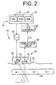
- Fig. 2 is a view for explaining a construction of the supersonic-wave emitting and receiving probe 44 which detects a femoral pulse wave as a heartbeat-synchronous signal produced from an upstream-side end of a prescribed second interval of the subject that is different from the above-described first interval.
- the probe 44 is worn on a body surface 52 of a femoral portion of the subject, such that the probe 44 is located at a position right above a prescribed artery, such as a femoral artery, of the subject.
- the probe 44 is identical with a probe that is employed in a well-known supersonic blood flow meter, and includes a generator 50 which generates a supersonic wave (i.e., an incident wave) having a prescribed frequency, fo; a piezoelectric element 56 which is held in close contact with the body surface 52 of the femoral portion and detects a reflected wave that is generated by the generator 50 and then is reflected from a blood flowing in an artery 54 running in the femoral portion; and a housing 58 which houses the generator 50 and the piezoelectric element 56.
- a supersonic wave i.e., an incident wave
- a piezoelectric element 56 which is held in close contact with the body surface 52 of the femoral portion and detects a reflected wave that is generated by the generator 50 and then is reflected from a blood flowing in an artery 54 running in the femoral portion
- a housing 58 which houses the generator 50 and the piezoelectric element 56.
- the probe 44 is detachably attached, with an attaching band, not shown, to the femoral portion such that a direction of arrangement of the generator 50 and the piezoelectric element 56 is parallel to a direction of running of the artery 54 and a direction of incidence of the supersonic wave generated by the generator 50 is opposite to a direction of flowing of the blood in the artery 54.
- the piezoelectric element 56 supplies an electric signal representing the reflected wave detected thereby, to the demodulator circuit 48.
- the reflected wave contains a Doppler shift, fd1, (Hz) corresponding to a velocity at which the blood flows in the artery 54, and the demodulator circuit 48 extracts, from the electric signal supplied from the piezoelectric element 56, a Doppler-shift signal, Sfd1, representing the Doppler shift fd1 contained in the electric signal.
- the Doppler-shift signal Sfd1 extracted by the demodulator circuit 48 is supplied to the control device 18 via an A/D converter 68.
- the second blood-flow-velocity measuring device 42 includes a supersonic-wave emitting and receiving probe 62, an oscillator 64, and a demodulator circuit 66 that have respective constructions identical with those of the counterparts of the first blood-flow-velocity measuring device 40.
- the supersonic-wave emitting and receiving probe 62 of the second blood-flow-velocity measuring device 42 is detachably attached, with an attaching band, not shown, to an ankle of a leg to the femoral portion of which the supersonic-wave emitting and receiving probe 44 of the first blood-flow-velocity measuring device 40 is attached, such that the probe 62 is located at a position right above a prescribed artery of the ankle, such as a posterior tibial artery.
- the probe 62 supplies, to the demodulator circuit 66, an electric signal containing a Doppler shift, fd2, corresponding to a velocity at which blood flows in the artery of the ankle, and the demodulator circuit 66 extracts, from the electric signal supplied from the probe 62, a Doppler-shift signal, Sfd2, representing the Doppler shift fd2 contained in the electric signal.
- the Doppler-shift signal Sfd2 extracted by the demodulator circuit 66 is supplied to the control device 18 via an A/D converter 70.
- the control device 18 is provided by a so-called microcomputer including a CPU (central processing unit) 72, a ROM (read only memory) 74, a RAM 76, and an I/O port, not shown.
- the CPU 72 processes signals according to the control programs pre-stored in the ROM 74 by utilizing the temporary-storage function of the RAM 76, and generates respective drive signals via the I/O port to respective drive circuits, not shown, so as to control the deflation control valve 26 and the air pump 28.
- the CPU 72 controls the deflation control valve 26 and the air pump 28 so as to change and maintain the pressure in the cuff 20 to and at a pre-set pulse-wave-detect pressure, e.g., 60 mmHg which is sufficiently lower than a diastolic blood pressure of the subject and which assures that the cuff-pulse-wave signal SM extracted by the pulse-wave filter circuit 34 has a sufficiently high strength or voltage.
- the CPU 54 generates respective drive signals via the I/O port to control the oscillators 46, 64. In response to those drive signals, the oscillators 46, 64 supply, to the corresponding generators 50, respective signals having a prescribed frequency (e.g., 10 MHz).
- the CPU 72 calculates a comparison value based on the signals supplied to the electronic device 18, and operates the display device 78 to display the thus calculated comparison value.
- Fig. 3 is a block diagram showing essential control functions of the control device 18.
- a first pulse-wave-propagation-velocity-related-information obtaining means 80 reads in the heart sounds detected by the heart-sound microphone 12 and the upper-arm pulse wave extracted by the pulse-wave filter circuit 34, and obtains, based on the heart sounds and the upper-arm pulse wave, pulse-wave-propagation-velocity-related information at the above-indicated first interval.
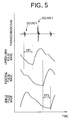
- the first pulse-wave-propagation-velocity-related-information obtaining means 80 calculates, as a first pulse-wave propagation time DT1, a time difference between a prescribed point on a waveform of the heart sounds detected by the heart-sound microphone 12 and a prescribed point on a waveform of the upper-arm pulse wave detected by the pulse-wave filter circuit 34, as illustrated in Fig. 5.
- a second pulse-wave-propagation-velocity-related-information obtaining means 81 includes a femoral-pulse-wave determining means 82, an ankle-pulse-wave determining means 84, and an information obtaining means 86.
- the change of the thus determined blood flow velocity V1 is defined as a femoral pulse wave.
- the change of the thus determined blood flow velocity V2 is defined as an ankle pulse wave.
- the information obtaining means 86 obtains pulse-wave-propagation-velocity-related information at the above-described second interval, based on respective heartbeat-synchronous pulses of the femoral pulse wave and the ankle pulse wave that are determined by the femoral-pulse-wave determining means 82 and the ankle-pulse-wave determining means 84 at a substantially same time as the time when the first pulse-wave-propagation-velocity-related-information obtaining means 80 reads in the heartbeat-synchronous signals as illustrated in Fig. 5.
- the information obtaining means 86 calculates, as a second pulse-wave propagation time DT2, a time difference between a prescribed point on a waveform of the femoral pulse wave and a prescribed point on a waveform of the ankle pulse wave, the femoral and ankle pulse waves being detected at a substantially same time as the time when the heart sounds and the upper-arm pulse wave are read in for obtaining the first pulse-wave-propagation-velocity-related information.
- a comparison-value calculating means 88 calculates a comparison value based on the first pulse-wave-propagation-velocity-related information obtained by the first pulse-wave-propagation-velocity-related-information obtaining means 80 and the second pulse-wave-propagation-velocity-related information obtained by the second pulse-wave-propagation-velocity-related-information obtaining means 81, and operates the display device 78 to display the thus calculated comparison value.
- the comparison value may be any value indicating a degree of relativity between the first pulse-wave-propagation-velocity-related information and the second pulse-wave-propagation-velocity-related information.
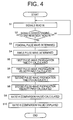
- Fig. 4 is a flow chart representing the control functions of the control device 18, shown in Fig. 3. Before the flow chart of Fig. 4 is implemented, the pressure in the cuff 20 is changed to, and is kept at, the above-described pulse-wave-detect pressure.
- Step S1 the control device 18 reads in the heart-sound signal SH, the cuff-pulse-wave signal SM, and the two Doppler-shift signals Sfd1, Sfd2. Then, at S2, the control device judges whether the control device has read in respective lengths of the above-indicated four heartbeat-synchronous signals that correspond to one heartbeat of the subject. If a negative judgment is made at S2, S1 and the following step is implemented again to continue reading in the heartbeat-synchronous signals.
- Fig. 5 is a graph showing a phonocardiogram, an upper-arm pulse wave, a femoral pulse wave, and an ankle pulse wave that are respectively based on the four heartbeat-synchronous signals read in while S1 and S2 are repeated.
- the control goes to S3 corresponding to the femoral-pulse-wave determining means 82.
- the control device determines, based on the one-heartbeat length of the Doppler-shift signal Sfd1 read in while S1 and S2 are repeated, a change of a velocity V1 at which blood flows in the prescribed artery of the femoral portion, i.e., a femoral pulse wave, according to the above-indicated Expression 2. Then, the control goes to S4 corresponding to the ankle-pulse-wave determining means 84.
- the control device determines, based on the one-heartbeat length of the Doppler-shift signal Sfd2 read in while S1 and S2 are repeated, a change of a velocity V2 at which blood flows in the prescribed artery of the ankle, i.e., an ankle pulse wave, according to the above-indicated Expression 3.
- the control goes to S5 where, as illustrated in Fig. 5, the control device determines a start point of a first heart sound, I, on a waveform of the heat sounds read in while S1 and S2 are repeated, and additionally determines a rising point corresponding to the first heart sound I, on a waveform of the upper-arm pulse wave read in while S1 and S2 are repeated. Finally, the control device determines, as a first pulse-wave propagation time DT1, a time difference between the start point of the first heart sound I and the rising point of the upper-arm pulse wave.
- S1, S2, S5, and S6 corresponds to the first pulse-wave-propagation-velocity-related-information obtaining means 80.
- the control goes to S7 and S8 corresponding to the information obtaining means 86.
- the control device determines a rising point on a waveform of the femoral pulse wave determined at S3, and additionally determines a rising point on a waveform of the ankle pulse wave determined at S4.
- the control device determines, as a second pulse-wave propagation time DT2, a time difference between the rising point of the femoral pulse wave and the rising point of the ankle pulse wave.
- the control goes to S8 to determine a second pulse-wave propagation velocity PWV2 based on the thus determined second pulse-wave propagation time DT2 according to the above-indicated Expression 4.
- S1 to S4, S7, and S8 corresponds to the second pulse-wave-propagation-velocity-related-information obtaining means 81.
- the control goes to S9 corresponding to the comparison-value determining means 88.
- the control device operates the display device 78 to display the ratio R calculated at S9.
- a normal range of the ratio R i.e., a range of the ratio R that is obtained from the subject when both the respective arteries present in the first and second intervals are normal, is dependent on the manner in which the first and second intervals are prescribed, the age of the subject, etc. If an actually calculated ratio R is a value outside the normal range, it can be diagnosed that either one of the two arteries in the first and second intervals suffers an angiopathy. In this case, the single value R does not suffice for identifying which one of the two arteries in the first and second intervals suffers a disease.
- a single ratio R suffices for identifying whether the artery in the other interval suffers an angiopathy. More specifically described, if the ratio R is smaller than the normal range, it can be judged that the artery in the other interval suffers stenosis; and if the ratio R is greater than the normal range, it can be judged that the artery in the other interval suffers sclerosis.
- a therapeutic effect of the treatment can be ascertained based on a time-wise change of the ratio R.
- one of the first and second intervals is fixed on a body portion of the subject and the other interval is moved over a plurality of body portions of the subject so as to obtain a plurality of ratios R corresponding to the respective body portions, it is possible to identify which one of the respective arteries in those body portions suffers a disease. For example, if a greater number of ratios R are outside the normal range, than the number of the ratios R within the normal range, it can be judged that the artery in the fixed interval has a disease.
- the control device obtains, at a substantially same time, the first pulse-wave propagation velocity PWV1 at the first interval, and the second pulse-wave propagation velocity PWV2 at the second interval, at Steps S1, S2, S5, and S6 (the first pulse-wave-propagation-velocity-related-information obtaining means 80), and Steps S1 to S4, S7, and S8 (the second pulse-wave-propagation-velocity-related-information obtaining means 81), and calculates the ratio R of the second pulse-wave propagation velocity PWV2 to the first pulse-wave propagation velocity PWV1, at Step S9 (the comparison-value calculating means 88).
- the ratio R is calculated based on the first pulse-wave propagation velocity PWV1 and the second pulse-wave propagation velocity PWV2 obtained at a substantially same time, and accordingly the ratio R is free of the influence of change of the blood pressure.
- an angiopathy can be diagnosed, with high accuracy, based on the ratio R.
- pulse-wave propagation velocity PWV can be measured between two arbitrary locations of the subject, an angiopathy can be diagnosed on an arbitrary body portion of the subject other than an inferior limb of the subject.
- pulse-wave propagation velocity PWV can be easily measured from even an inferior limb of the subject, an angiopathy of the inferior limb can be diagnosed with high accuracy. Furthermore, since pulse-wave propagation velocity PWV can be iteratively measured in synchronism with each heartbeat of the subject, a quick diagnosis can be made.
- the first interval is so prescribed as to extend from the subject's heart to the upper arm 22, and the second interval is so prescribed as to extend from the femoral portion to the ankle.
- each of the first and second intervals on an arbitrary body portion of a living subject.
- the first interval may be so prescribed as to extend from the subject's heart to the neck portion.
- the heart-sound microphone 12 is employed as the first heartbeat-synchronous-signal detecting device.
- an electrocardiograph for detecting an electrocardiogram may be employed as the first heartbeat-synchronous-signal detecting device, or the third heartbeat-synchronous-signal detecting device.
- the pulse-wave filter circuit 34 for extracting the pulse wave from the change of pressure in the cuff 20 is employed as the second heartbeat-synchronous-signal detecting device.
- a blood-flow-velocity measuring device may be employed as the second heartbeat-synchronous-signal detecting device.
- a cuff at an upstream-side or downstream-side end of the second interval and employ, as the third or fourth heartbeat-synchronous-signal detecting device, a pulse-wave filter circuit for extracting a pulse wave from the change of pressure in the cuff.
- each of the first to fourth heartbeat-synchronous-signal detecting devices may be provided by a photoelectric-pulse-wave detecting probe for measuring a blood oxygen saturation; a pressure-pulse-wave sensor which is adapted to be pressed against a prescribed artery, such as a radial artery, via skin and detects a pressure pulse wave from the artery; an impedance-pulse-wave sensor which detects an impedance of, e.g., an arm or a finger via electrodes; or a photoelectric-pulse-wave sensor which is adapted to be worn on, e.g., a free end portion of a finger and detects pulsation.
Landscapes
- Health & Medical Sciences (AREA)
- Life Sciences & Earth Sciences (AREA)
- Physics & Mathematics (AREA)
- Surgery (AREA)
- Public Health (AREA)
- General Health & Medical Sciences (AREA)
- Veterinary Medicine (AREA)
- Animal Behavior & Ethology (AREA)
- Engineering & Computer Science (AREA)
- Biomedical Technology (AREA)
- Heart & Thoracic Surgery (AREA)
- Medical Informatics (AREA)
- Molecular Biology (AREA)
- Pathology (AREA)
- Biophysics (AREA)
- Cardiology (AREA)
- Hematology (AREA)
- Physiology (AREA)
- Vascular Medicine (AREA)
- Acoustics & Sound (AREA)
- Radiology & Medical Imaging (AREA)
- Nuclear Medicine, Radiotherapy & Molecular Imaging (AREA)
- Measuring Pulse, Heart Rate, Blood Pressure Or Blood Flow (AREA)
- Ultra Sonic Daignosis Equipment (AREA)
Applications Claiming Priority (2)
| Application Number | Priority Date | Filing Date | Title |
|---|---|---|---|
| JP2001312208 | 2001-10-10 | ||
| JP2001312208A JP3530892B2 (ja) | 2001-10-10 | 2001-10-10 | 血管障害診断装置 |
Publications (2)
| Publication Number | Publication Date |
|---|---|
| EP1302154A2 true EP1302154A2 (de) | 2003-04-16 |
| EP1302154A3 EP1302154A3 (de) | 2003-06-04 |
Family
ID=19130902
Family Applications (1)
| Application Number | Title | Priority Date | Filing Date |
|---|---|---|---|
| EP02022645A Withdrawn EP1302154A3 (de) | 2001-10-10 | 2002-10-09 | Diagnosegerät für Angiopathie |
Country Status (3)
| Country | Link |
|---|---|
| US (1) | US6893400B2 (de) |
| EP (1) | EP1302154A3 (de) |
| JP (1) | JP3530892B2 (de) |
Families Citing this family (25)
| Publication number | Priority date | Publication date | Assignee | Title |
|---|---|---|---|---|
| DE60334007D1 (de) | 2002-10-01 | 2010-10-14 | Nellcor Puritan Bennett Inc | Verwendung eines Kopfbandes zur Spannungsanzeige und System aus Oxymeter und Kopfband |
| US7047056B2 (en) | 2003-06-25 | 2006-05-16 | Nellcor Puritan Bennett Incorporated | Hat-based oximeter sensor |
| US8412297B2 (en) | 2003-10-01 | 2013-04-02 | Covidien Lp | Forehead sensor placement |
| JP4813815B2 (ja) * | 2005-04-04 | 2011-11-09 | フクダ電子株式会社 | 血管硬化度算出装置および血管硬化度算出プログラム |
| US8920343B2 (en) | 2006-03-23 | 2014-12-30 | Michael Edward Sabatino | Apparatus for acquiring and processing of physiological auditory signals |
| WO2008073140A2 (en) * | 2006-05-15 | 2008-06-19 | Empirical Technologies Corporation | Wrist plethysmograph |
| US8364220B2 (en) | 2008-09-25 | 2013-01-29 | Covidien Lp | Medical sensor and technique for using the same |
| US8257274B2 (en) | 2008-09-25 | 2012-09-04 | Nellcor Puritan Bennett Llc | Medical sensor and technique for using the same |
| JP5200881B2 (ja) * | 2008-11-20 | 2013-06-05 | オムロンヘルスケア株式会社 | 血圧情報測定装置 |
| US8515515B2 (en) | 2009-03-25 | 2013-08-20 | Covidien Lp | Medical sensor with compressible light barrier and technique for using the same |
| US8781548B2 (en) | 2009-03-31 | 2014-07-15 | Covidien Lp | Medical sensor with flexible components and technique for using the same |
| JP5615073B2 (ja) * | 2010-07-20 | 2014-10-29 | オムロンヘルスケア株式会社 | 測定装置 |
| CN102985001B (zh) * | 2010-07-21 | 2016-08-03 | 皇家飞利浦电子股份有限公司 | 腹主动脉瘤的检测和监控 |
| WO2013090850A1 (en) | 2011-12-14 | 2013-06-20 | California Institute Of Technology | Noninvasive systems for blood pressure measurement in arteries |
| KR20140107407A (ko) | 2011-12-22 | 2014-09-04 | 캘리포니아 인스티튜트 오브 테크놀로지 | 고유 주파수 혈류역학 파형 분석 |
| CA2876506A1 (en) * | 2012-08-13 | 2014-02-20 | Morteza Gharib | Noninvasive systems for aortic aneurysm evaluation |
| US20140086461A1 (en) * | 2012-09-25 | 2014-03-27 | The Johns Hopkins University | Method and system for determining time-based index for blood circulation from angiographic imaging data |
| CN104510494B (zh) * | 2013-09-30 | 2017-02-01 | 中国人民解放军第二军医大学 | 一种颈总动脉m型超声波图像后处理装置及方法 |
| MX368824B (es) | 2013-10-18 | 2019-10-17 | California Inst Of Techn | Análsis de frecuencia intrínseca para fracción de eyección de ventrículo izquierdo o determinación de volumen sistólico. |
| EP3096682A4 (de) | 2014-01-21 | 2017-08-23 | California Institute Of Technology | Tragbare elektronische hämodynamische sensorsysteme |
| JP6371334B2 (ja) * | 2016-05-27 | 2018-08-08 | 株式会社ユネクス | 超音波断面画像測定装置 |
| WO2018164181A1 (ja) * | 2017-03-07 | 2018-09-13 | 国立大学法人東京大学 | 組織弾性の測定装置及び測定方法 |
| KR20210008354A (ko) * | 2018-05-10 | 2021-01-21 | 벤더르빌트 유니버시티 | 대상체 평가를 위한 비 침습성 정맥 파형 분석 |
| CN111000537B (zh) * | 2019-12-24 | 2022-05-27 | 中国人民解放军陆军军医大学第一附属医院 | 一种修正年龄性别和血压对脉搏波传播速度的影响的方法 |
| US20240065675A1 (en) * | 2023-10-16 | 2024-02-29 | Gaurang Nandkishor Vaidya | Automatic doppler derived blood pressure |
Family Cites Families (9)
| Publication number | Priority date | Publication date | Assignee | Title |
|---|---|---|---|---|
| JPS52146987A (en) | 1976-06-01 | 1977-12-07 | Yoshihisa Ushiyama | Digital pulse wave propagation speedometer |
| US5033472A (en) * | 1989-02-23 | 1991-07-23 | Nihon Kohden Corp. | Method of and apparatus for analyzing propagation of arterial pulse waves through the circulatory system |
| DE59107232D1 (de) | 1990-07-18 | 1996-02-22 | Avl Medical Instr Ag | Einrichtung und Verfahren zur Blutdruckmessung |
| US5503156A (en) * | 1994-03-11 | 1996-04-02 | Millar Instruments, Inc. | Noninvasive pulse transducer for simultaneously measuring pulse pressure and velocity |
| JP2764702B2 (ja) * | 1994-03-30 | 1998-06-11 | 日本光電工業株式会社 | 血圧監視装置 |
| JP3318727B2 (ja) | 1994-06-06 | 2002-08-26 | 日本光電工業株式会社 | 脈波伝播時間方式血圧計 |
| JP3140007B2 (ja) | 1999-05-06 | 2001-03-05 | 日本コーリン株式会社 | 下肢上肢血圧指数測定装置 |
| JP3027750B1 (ja) * | 1999-05-17 | 2000-04-04 | 日本コーリン株式会社 | 下肢上肢血圧指数測定装置および下肢血圧測定装置 |
| DE19960452B8 (de) | 1999-12-15 | 2005-01-13 | Dr.-Ing. Wolfgang Rentsch Medizintechnik - Elektronik Ohg Reco | Verfahren und Anordnung zur Auswertung von Pulswellengeschwindigkeiten |
-
2001
- 2001-10-10 JP JP2001312208A patent/JP3530892B2/ja not_active Expired - Fee Related
-
2002
- 2002-10-03 US US10/262,844 patent/US6893400B2/en not_active Expired - Fee Related
- 2002-10-09 EP EP02022645A patent/EP1302154A3/de not_active Withdrawn
Also Published As
| Publication number | Publication date |
|---|---|
| US20030069508A1 (en) | 2003-04-10 |
| JP3530892B2 (ja) | 2004-05-24 |
| EP1302154A3 (de) | 2003-06-04 |
| JP2003116798A (ja) | 2003-04-22 |
| US6893400B2 (en) | 2005-05-17 |
Similar Documents
| Publication | Publication Date | Title |
|---|---|---|
| US6893400B2 (en) | Angiopathy diagnosing apparatus | |
| US6355000B1 (en) | Superior-and-inferior-limb blood-pressure index measuring apparatus | |
| US5309916A (en) | Blood pressure measuring device and method | |
| US6843772B2 (en) | Inferior-and-superior-limb blood-pressure-index measuring apparatus | |
| FI103760B (fi) | Menetelmä ja järjestely verenpaineen mittauksessa | |
| JP2831471B2 (ja) | 誘発された摂動を測定して生理学的パラメータを測定するための装置および方法 | |
| US5791347A (en) | Motion insensitive pulse detector | |
| US6524257B2 (en) | Superior-and-inferior-limb blood-pressure index measuring apparatus | |
| US6969355B2 (en) | Arteriostenosis diagnosing apparatus | |
| WO2000074563A1 (en) | Method and device for arterial blood pressure measurement | |
| US6440079B1 (en) | Superior-and-inferior-limb blood-pressure index measuring apparatus | |
| US6743179B2 (en) | Arteriostenosis inspecting apparatus | |
| US6565515B2 (en) | Pulse-wave-propagation-velocity-relating-information obtaining apparatus and blood-pressure-index measuring apparatus | |
| US6758819B2 (en) | Pulse-wave-propagation-velocity measuring apparatus | |
| US6669646B1 (en) | Arteriosclerosis evaluating apparatus | |
| EP0168461A1 (de) | Messung von physiologischen grössen | |
| CN113491511A (zh) | 光学式医疗检测装置 | |
| JP3712418B2 (ja) | 誘発された摂動を測定してヒト動脈系の物理的状態を決定するための装置および方法 | |
| JPH0579325B2 (de) | ||
| US20020147403A1 (en) | Pulse-wave-propagation-velocity measuring apparatus | |
| EP1671581A1 (de) | Verfahren und Gerät zur Detektion arterieller Okklusionen in Armen und Beinen | |
| US20040097817A1 (en) | Superior-limb arteriostenosis evaluating apparatus | |
| KR20020013820A (ko) | 심음과 맥파를 이용한 맥파전달속도 측정시스템 | |
| EP1340455A1 (de) | Vorrichtung zum Bestimmen eines Standardwertes mit Bezug zur Pulswellenlaufzeit und Vorrichtung zum Feststellen eines Wertes mit Bezug zur Pulswellenlaufzeit | |
| WO2016035041A1 (en) | Apparatus and method for non-invasive pressure measurement of a fluid confined in a vessel with elastic or rigid walls fitted with an elastic window |
Legal Events
| Date | Code | Title | Description |
|---|---|---|---|
| PUAI | Public reference made under article 153(3) epc to a published international application that has entered the european phase |
Free format text: ORIGINAL CODE: 0009012 |
|
| AK | Designated contracting states |
Designated state(s): AT BE BG CH CY CZ DE DK EE ES FI FR GB GR IE IT LI LU MC NL PT SE SK TR |
|
| AX | Request for extension of the european patent |
Extension state: AL LT LV MK RO SI |
|
| PUAL | Search report despatched |
Free format text: ORIGINAL CODE: 0009013 |
|
| AK | Designated contracting states |
Designated state(s): AT BE BG CH CY CZ DE DK EE ES FI FR GB GR IE IT LI LU MC NL PT SE SK TR |
|
| AX | Request for extension of the european patent |
Extension state: AL LT LV MK RO SI |
|
| AKX | Designation fees paid | ||
| REG | Reference to a national code |
Ref country code: DE Ref legal event code: 8566 |
|
| STAA | Information on the status of an ep patent application or granted ep patent |
Free format text: STATUS: THE APPLICATION IS DEEMED TO BE WITHDRAWN |
|
| 18D | Application deemed to be withdrawn |
Effective date: 20031205 |