EP1302174B1 - Instrument médical ou dentaire d'usinage par abrasion de tissus corporels ou d'un matériau de remplacement - Google Patents
Instrument médical ou dentaire d'usinage par abrasion de tissus corporels ou d'un matériau de remplacement Download PDFInfo
- Publication number
- EP1302174B1 EP1302174B1 EP03001043A EP03001043A EP1302174B1 EP 1302174 B1 EP1302174 B1 EP 1302174B1 EP 03001043 A EP03001043 A EP 03001043A EP 03001043 A EP03001043 A EP 03001043A EP 1302174 B1 EP1302174 B1 EP 1302174B1
- Authority
- EP
- European Patent Office
- Prior art keywords
- handpiece
- medical
- treatment instrument
- sleeve
- tool
- Prior art date
- Legal status (The legal status is an assumption and is not a legal conclusion. Google has not performed a legal analysis and makes no representation as to the accuracy of the status listed.)
- Expired - Lifetime
Links
Images



Classifications
-
- A—HUMAN NECESSITIES
- A61—MEDICAL OR VETERINARY SCIENCE; HYGIENE
- A61C—DENTISTRY; APPARATUS OR METHODS FOR ORAL OR DENTAL HYGIENE
- A61C1/00—Dental machines for boring or cutting ; General features of dental machines or apparatus, e.g. hand-piece design
- A61C1/02—Dental machines for boring or cutting ; General features of dental machines or apparatus, e.g. hand-piece design characterised by the drive of the dental tools
- A61C1/05—Dental machines for boring or cutting ; General features of dental machines or apparatus, e.g. hand-piece design characterised by the drive of the dental tools with turbine drive
- A61C1/052—Ducts for supplying driving or cooling fluid, e.g. air, water
-
- A—HUMAN NECESSITIES
- A61—MEDICAL OR VETERINARY SCIENCE; HYGIENE
- A61B—DIAGNOSIS; SURGERY; IDENTIFICATION
- A61B17/00—Surgical instruments, devices or methods
- A61B17/16—Instruments for performing osteoclasis; Drills or chisels for bones; Trepans
- A61B17/1613—Component parts
- A61B17/1622—Drill handpieces
-
- A—HUMAN NECESSITIES
- A61—MEDICAL OR VETERINARY SCIENCE; HYGIENE
- A61B—DIAGNOSIS; SURGERY; IDENTIFICATION
- A61B17/00—Surgical instruments, devices or methods
- A61B17/16—Instruments for performing osteoclasis; Drills or chisels for bones; Trepans
- A61B17/1613—Component parts
- A61B17/1626—Control means; Display units
-
- A—HUMAN NECESSITIES
- A61—MEDICAL OR VETERINARY SCIENCE; HYGIENE
- A61C—DENTISTRY; APPARATUS OR METHODS FOR ORAL OR DENTAL HYGIENE
- A61C1/00—Dental machines for boring or cutting ; General features of dental machines or apparatus, e.g. hand-piece design
- A61C1/02—Dental machines for boring or cutting ; General features of dental machines or apparatus, e.g. hand-piece design characterised by the drive of the dental tools
- A61C1/07—Dental machines for boring or cutting ; General features of dental machines or apparatus, e.g. hand-piece design characterised by the drive of the dental tools with vibratory drive, e.g. ultrasonic waves
-
- A—HUMAN NECESSITIES
- A61—MEDICAL OR VETERINARY SCIENCE; HYGIENE
- A61C—DENTISTRY; APPARATUS OR METHODS FOR ORAL OR DENTAL HYGIENE
- A61C1/00—Dental machines for boring or cutting ; General features of dental machines or apparatus, e.g. hand-piece design
- A61C1/08—Machine parts specially adapted for dentistry
-
- A—HUMAN NECESSITIES
- A61—MEDICAL OR VETERINARY SCIENCE; HYGIENE
- A61B—DIAGNOSIS; SURGERY; IDENTIFICATION
- A61B17/00—Surgical instruments, devices or methods
- A61B17/16—Instruments for performing osteoclasis; Drills or chisels for bones; Trepans
- A61B17/1613—Component parts
- A61B17/1622—Drill handpieces
- A61B17/1624—Drive mechanisms therefor
-
- A—HUMAN NECESSITIES
- A61—MEDICAL OR VETERINARY SCIENCE; HYGIENE
- A61B—DIAGNOSIS; SURGERY; IDENTIFICATION
- A61B17/00—Surgical instruments, devices or methods
- A61B17/16—Instruments for performing osteoclasis; Drills or chisels for bones; Trepans
- A61B17/1613—Component parts
- A61B17/1633—Sleeves, i.e. non-rotating parts surrounding the bit shaft, e.g. the sleeve forming a single unit with the bit shaft
-
- A—HUMAN NECESSITIES
- A61—MEDICAL OR VETERINARY SCIENCE; HYGIENE
- A61B—DIAGNOSIS; SURGERY; IDENTIFICATION
- A61B17/00—Surgical instruments, devices or methods
- A61B17/16—Instruments for performing osteoclasis; Drills or chisels for bones; Trepans
- A61B17/1659—Surgical rasps, files, planes, or scrapers
-
- A—HUMAN NECESSITIES
- A61—MEDICAL OR VETERINARY SCIENCE; HYGIENE
- A61B—DIAGNOSIS; SURGERY; IDENTIFICATION
- A61B90/00—Instruments, implements or accessories specially adapted for surgery or diagnosis and not covered by any of the groups A61B1/00 - A61B50/00, e.g. for luxation treatment or for protecting wound edges
- A61B90/03—Automatic limiting or abutting means, e.g. for safety
- A61B2090/031—Automatic limiting or abutting means, e.g. for safety torque limiting
-
- A—HUMAN NECESSITIES
- A61—MEDICAL OR VETERINARY SCIENCE; HYGIENE
- A61B—DIAGNOSIS; SURGERY; IDENTIFICATION
- A61B90/00—Instruments, implements or accessories specially adapted for surgery or diagnosis and not covered by any of the groups A61B1/00 - A61B50/00, e.g. for luxation treatment or for protecting wound edges
- A61B90/36—Image-producing devices or illumination devices not otherwise provided for
-
- A—HUMAN NECESSITIES
- A61—MEDICAL OR VETERINARY SCIENCE; HYGIENE
- A61C—DENTISTRY; APPARATUS OR METHODS FOR ORAL OR DENTAL HYGIENE
- A61C1/00—Dental machines for boring or cutting ; General features of dental machines or apparatus, e.g. hand-piece design
- A61C1/08—Machine parts specially adapted for dentistry
- A61C1/18—Flexible shafts; Clutches or the like; Bearings or lubricating arrangements; Drives or transmissions
- A61C1/185—Drives or transmissions
- A61C1/186—Drives or transmissions with torque adjusting or limiting means
Definitions
- the invention relates to a medical or dental treatment instrument according to the preamble of claim 1.
- a treatment instrument for the machining of body tissue or a substitute (tissue replacement or a prosthesis) treatment instruments with an abrasive tool and a vibration drive of a preferably lying in the sonic or ultrasonic range frequency are known.
- a treatment instrument is e.g. described in WO 96/14024. It has an elongate handpiece in the form of a sleeve-shaped housing, in the front region of a vibrating part is elastically yielding, which is in the operation mode by a vibration exciter vibratable and in its front region by a holding device with the tool is detachably connectable.
- the handpiece has a coupling part, in particular a screw or plug-in coupling part, with which it can be coupled with a so-called connector of a supply device in the form of a flexible hose which extends to a supply and control device and media lines for power supply and supply of Treatment media such as Water, air or a spray containing.
- a coupling part in particular a screw or plug-in coupling part, with which it can be coupled with a so-called connector of a supply device in the form of a flexible hose which extends to a supply and control device and media lines for power supply and supply of Treatment media such as Water, air or a spray containing.
- a treatment instrument of this type can also be used as a dental scaler in the field of dental medicine, such a treatment instrument known from the Austrian patent specification 379 505 having a tool with a wedge-shaped working tip.
- the known treatment instruments are tuned with respect to their vibration function to a particular kind of tool or to a specific processing. As a result, the scope of use of such a treatment instrument is limited.
- the invention has for its object to further improve a treatment instrument of the type specified in that it is suitable for a wider range of applications.
- the vibration generator is first assigned a control device for increasing and decreasing its output power, which enables power adjustment in stages or steplessly.
- the treatment instrument according to the invention is suitable for a wide range of applications, e.g. for machining with different tools, in particular different size and / or shape and / or Abtrags sparkle (abrasiveness), with which it is optional equippable.
- the performance of the treatment instrument is adaptable to different intensive operations, namely rough and fine machining or rough, medium and fine machining, these adjustments taking into account the same materials or different materials of the tool and / or or of the material to be processed.
- the embodiment according to the invention also makes it possible to adapt the treatment instrument to different types of processing, e.g. for the removal of coverings, as is the case with a scaler, or for the preparation of a cavity, as e.g. in the preparation of a tooth is the case.
- a medical or dental treatment instrument of the present type may be prone to failure in terms of its power output, since the vibration generator is to deliver a constant and certain vibration power in order to achieve an optimal vibration mode.
- the optimal vibration mode can be relatively easily affected by different performance levels, with hardly unavoidable vibration resonances a can exert an impairing effect on the vibration behavior. This applies in particular to a treatment instrument whose vibration exciter can be driven by compressed air.
- the treatment instrument according to the invention is therefore also distinguished by the fact that a constant oscillation power is achieved.
- a pressure regulator is assigned to the treatment instrument, which ensures a constant at the vibration exciter working pressure.
- this is achieved in that the valve spool of a control valve is acted upon by the pressure applied to the vibration against the force of a spring and has a control edge for controlling the size of the valve opening.
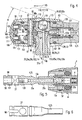
- the main parts of the generally designated 1 treatment instrument are an elongated or rod-shaped handpiece 2 with a grip sleeve 3, in which a preferably elongated or rod-shaped vibrating part 4 is mounted swingably and by a vibration exciter 5 in oscillations or driven, and a holding device 6 for at least a treatment tool 7, which has a tool shaft 8, which is releasably connectable to the holding device 6.
- the treatment instrument 1 with at least one, preferably a plurality of so-called media lines, the supply of drive energy and treatment media such as a treatment liquid and / or compressed air and the supply of light to the treatment site.
- a light pipe 9 is provided, which extends longitudinally through the handpiece 2 into its front end region and opens out at an opening 11 directed towards the treatment site, and forms a lighting device 12.
- a conduit 13 extending longitudinally through the handpiece 2 for a treatment or cooling fluid, here water, is provided, which likewise opens out at an outlet opening 14 (FIGS. 4 and 7) arranged in the front end region of the handpiece 2 and directed towards the treatment site and forms a delivery device.
- a supply line 15 is provided for drive energy, which extends longitudinally through the handpiece 2 to the drive of the vibrator 5.
- a driven by compressed air vibration exciter 5 is provided and the supply line 15 is a compressed air line, which extends to the vibration exciter 5.
- the handpiece 2 is releasably connected by a quick coupling or by a screw or plug-in coupling, in particular by a freely rotatable plug-in rotary coupling 16, with an indicated connector 17, which is connected by a flexible supply line 18 to a supply and control device, not shown
- the plug-in rotary joint 16 is formed in the present embodiment by a hollow cylindrical or stepped hollow cylindrical coupling recess 16a and therein with play insertable cylindrical or stepped cylindrical coupling pin 16b, wherein in the present embodiment, the coupling recess 16a is arranged in the rear region of the handpiece 2 and the coupling pin 16b protruding from the connector 17.
- the media lines enforce the plug-in rotary joint 16, so that in an optional separation of the handpiece 2 from the connector 17, the media lines are automatically interrupted.
- the light pipe 9 passes through the plug-in rotary joint 16 coaxially.
- a rear light line section extending coaxially in a corresponding receiving bore to the front end portion of the coupling pin 16b to which shoots with a parting line a front light pipe section which extends to the orifice 14.
- the front light pipe section is preferably formed by a light guide 9a of light-conducting material, such as glass or plastic, which may be a flexible light guide or a rigid light guide in the form of a fitting.
- the cross-sectional shape of the light guide 9 is preferably round behind and further elipsenförmig further ahead.
- the rear light pipe section can also by an optical fiber, not shown, or by an electrical line with one in the front Formed end portion of the coupling pin 16 b arranged lamp 19 may be formed, which is preferably arranged sunk in
- the two other media lines 13, 15 pass through the hollow cylindrical parting line 21 between the coupling pin 16b and the wall of the coupling recess 16a Z-shaped radially from the inside to the outside, wherein the respective existing in the lateral surface of the coupling pin 16a and the inner circumferential surface of the coupling recess 16b openings in one Ring groove 22 in the lateral surface or in the inner circumferential surface.
- the media passage is guaranteed in each rotational position of the plug-in rotary joint 16 also over 360 ° addition.
- the Z-shaped penetration points are each sealed by a sealing ring 23, in particular an O-ring, which is arranged on both sides of the Z-shaped penetration point in an annular groove in the lateral surface of the coupling pin 16b or in the inner circumferential surface of the coupling recess 16a.
- a sealing ring 23 in particular an O-ring, which is arranged on both sides of the Z-shaped penetration point in an annular groove in the lateral surface of the coupling pin 16b or in the inner circumferential surface of the coupling recess 16a.
- connectors 17, e.g. Connecting sleeves 24, be arranged for in the flexible supply line 18 extending media line sections.
- the holding device 6 for the tool 7 is arranged in the front end region of the oscillating part 4.
- the oscillating member 4 is a rod or sleeve-shaped body which is arranged in the front half of the handpiece 2 and forms a handpiece shaft 25 which protrudes from the front end of the handpiece 2 and can extend straight or with respect to the longitudinal central axis 26 of Handpiece 2 may include an acute angle W of about 10 to 30 °, in particular about 20 °.
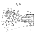
- the holding device 6 has a transversely or preferably at right angles to the handpiece shaft 25 extending plug hole 27, which is preferably a blind hole and thus only open on one side, and in which the tool shaft 8 with little movement play can be inserted.
- a securing recess 28 is provided in the tool shank 8 into which an adjustable in the longitudinal direction of the handpiece shaft 25 securing member 29 is moved, which between its moved into the securing recess 28 securing position and a moved out, the tool shank 8 releasing Release position is adjustable and is preferably acted upon by the force of a spring in its securing position.
- the securing recess 28 may be an annular groove. It can also be provided more evenly distributed on the circumference arranged calotte, which may preferably have conical depressions with a central core-free bore.
- a bearing sleeve 35 made of elastic material, e.g. Plastic or rubber, in the through hole 36 of the vibrating rod 4 a is received with peripheral contact, so that it is centered by the bearing sleeve 35.
- the bearing sleeve 35 in its front and rear end portion radially inwardly projecting, preferably in cross-section rounded Lagerwülste 37, between which an oscillating rod 4a surrounding annular gap 38 is arranged.
- the bearing sleeve 35 may be fixedly mounted in a sleeve cap 39 fixedly connected to a sleeve housing 41, e.g. is screwed therein, as shown in FIG. 1, and the peripherally complete each other steplessly and form the grip sleeve 3.
- the bearing sleeve 35 projects beyond the sleeve housing 41 or the sleeve cap 39 and thus forms a protective jacket 35a for the handpiece shaft 25, which extends as far as or in the vicinity of the holding device 6 or an actuating member 92a to be described.
- a positive connection 40 is provided with an annular groove 40a and a ring pin 40b which engages therein and which automatically engages on insertion due to the elastically deformable material.
- the protruding elastic or soft-elastic protective sheath 35a when treated from vibration, will interfere with the contact of the tool shank with adjacent body parts, e.g. Teeth, avoided.
- the protective jacket can also be arranged and fixed as a separate component only on the tool shank 25, for. B. slid on it elastically clamping or fixed by means of a corresponding positive connection 40 thereon.
- the radially and axially elastically yielding bearing for the vibrating rod 4 a is formed by a bearing ring 42 made of elastically deformable material such as plastic or rubber, in particular an O-ring, in which the vibrating rod 4 a is seated with external contact the bearing ring 42 is received and supported in a sleeve 43 surrounding the vibrating rod 4a with a radial annular space 43a or in a rearwardly extending from the latter bearing part 44 and which is mounted in the sleeve housing 41 radially and axially stationary or preferably movable against a restoring force , is inserted in particular from the rear and rests with a front shoulder surface on a rear shoulder surface of the sleeve housing 41.
- the bearing part 44 has a front sleeve extension 45, which surrounds the vibrating rod 4 a with a radial distance, wherein the rear end of the Swing bar 4a in a space 46 of the bearing part 44 ends.
- the front sleeve extension 45 is connected in an overlapping arrangement with the sleeve 43, preferably closing or plugged in and sealed by a seal, which is formed here by the bearing ring 42.
- the oscillating rod 4 a can be arranged with the associated bearing elements coaxially to the longitudinal central axis 26.
- the longitudinal center axis 26a of the oscillating rod 4a bezgl.
- the longitudinal central axis of the front end portion of the grip sleeve 3 and the bearing sleeve 35 offset from the laterally disposed tool body 8a side and thus arranged eccentrically, wherein the Ausmündungsö réelle 11 and the associated passage 11a, in which the light guide 9a is received, bezgl.
- the vibrating rod 4a is arranged to the tool facing side, here in the corresponding eccentric bearing sleeve 35.
- the rear end of the light guide 9a is arranged by means of a bearing sleeve 47 in an extension of the coupling recess 16a, wherein the light guide 9a extends through an eccentric passage 44a in the bearing part 44 as a laterally arcuate shaped part forward.
- the bearing part 44 has an eccentric rear pipe socket 48 to which a sleeve projection 49a of a coupling sleeve 49 adjoins, which alone or with the bearing part 44 as a composite component is mounted radially on all sides and axially movable against a restoring force in the sleeve housing 41 ,
- at least one of the coupling sleeve 49 surrounding bearing ring 51 made of elastically deformable material, which centers the coupling sleeve 49 due to its elastic restoring force and radially resiliently superimposed.
- the bearing ring 51 preferably has an inner flange 53 which engages behind a rear shoulder surface 52 and supports the coupling sleeve 49 in an elastically yielding manner, also with respect to axial rearwardly directed movements.
- the assembly formed by the coupling sleeve 49 and the bearing member 44 between the inner flange 53 and the bearing ring 42 is resiliently mounted in both axial directions.
- an axially and preferably also diametrically effective bearing ring 50 be arranged elastically yielding material, wherein due to the elastic restoring force of the elastically yielding bearing elements centering is ensured, both axially and diametrically.
- the bearing ring 51 is positively fixed in the axial direction, for example, characterized in that its inner flange 53 bears against a forwardly directed shoulder surface of a threaded sleeve 54 screwed into the rear end of the sleeve housing 41.
- a manually überdrückbare latching device 55 is provided for überdrückbaren latching in the coupling end position.
- the latching device 55 one or more distributed on the circumference in radial holes of the coupling sleeve 49 arranged, preferably formed by balls Verrastungsetti formed that can so far dive into the holes that the radially inner ends of the latching elements in an annular groove in Coupling pin 16b can engage.
- the latching elements are automatically pushed out against a radially inwardly acting spring in the form of a spring ring 59 from the annular groove.
- the holes are tapered at their inner ends, so that the one or more Verrastungsetti, preferably balls with removed coupling pin 16b can not fall inward.
- the media lines extend in the connector 17 as e.g. axially parallel channels 13a, 15a, which continue in the associated passage transverse plane in the form of angular channels in the coupling pin 16b and in the coupling sleeve 49, wherein a passage transverse plane E1 with respect to the other passage transverse plane E2 of the compressed air line is axially offset and the angular channels are designated in the coupling sleeve 49 with 13b, 15b.
- a tube or hose 13c which is connected downstream with another tube or tube 13d, which passes through a rear wall 44b of the bearing part 44 in a bushing 44c sealed and in the cavity 61 of the sleeve-shaped Oscillating rod 4a extends into its central region in which an end sleeve 62 sealed by means of one or two sealing rings 62a sitting in the sleeve-shaped oscillating rod 4a and is tightly connected to the tube 13d, in particular is placed thereon.
- the vibration generator 5 is associated with a control device for reducing or increasing its power. As a result, its performance or the intensity of the vibration or vibrations and the size of the amplitudes can be selectively reduced or increased and thus set.
- a power regulator 71 to be described in detail for automatic regulation of a preferably constant power and / or a preferably manually adjustable control device 72 may be provided, with or with which the power or the drive energy quantity that can be supplied to the vibration generator 5 is variable and can be reduced and increased and is automatically or in steps or continuously adjustable by a manual adjustment device 73.
- the performance of the treatment instrument to the work to be done eg coarse and fine work or coarse, medium and fine work or to different types of treatment and / or be adapted in terms of shape and / or size and / or coarse and fine or coarse, medium and / or fine effectiveness different tools 7.
- the manually operable adjusting device 73 has an adjusting member 74 which is manually accessible from the outside and axially or circumferentially adjustable and is in driving connection with the control device 72 or forms a control device.
- the adjusting member 74 is an adjusting sleeve 74a which surrounds the handpiece 2 preferably in the rear region and in particular recessed in a ring guide forming annular recess 75 and axially or preferably in the circumferential direction is adjustable.
- the annular recess 75 is bounded on the back by a shoulder surface of the screw-54.
- a support web 76 radially inwardly, which extends over part of the circumference and slots 77a, 77b in the sleeve housing 41 and the radially inwardly arranged components, here in the coupling sleeve 49 and the bearing ring 51, with play and carries at its inner end a segment 78 extending over a portion of the circumference, which has on one side a sloping or curved surface 79, which cooperates with an adjusting 81, which is in operative connection with the control device 72, as shown in FIG. 3 schematically and Figs. 1 and 2 show as an exemplary embodiment.
- the sloping or cam surface 79 may be disposed on the front side and rear side of the segment 78.
- the sloping or cam surface 79 is front-mounted, and the adjusting member 81 is an axially parallel in a guide 82 slidably mounted adjusting pin 81 a, by the force of a Spring, here a compression spring against the inclined or curved surface 79 is acted upon and thus able to tap it in a reciprocating rotation of the adjusting member 74.
- the guide 82 may be formed by an axparallele bore in the rotationally secured coupling sleeve 49.
- the adjusting device 73 may be adjustable in stages or continuously. In both cases, it is advantageous to associate the setting device 73 with a locking device 83, which makes it possible to fix the setting device 73 in the respectively set position, thereby preventing unintentional adjustment.
- This may be a braking device, which prevents unintentional adjustment of the adjusting member 74 due to their stiffness.
- a überdschreibbare Verrastungsvorraum 84 is provided with a preferably formed by a ball, radially movably guided latching element 85 which is manually überdschreibbar when turning the adjusting sleeve 74a in dome 86 and disengaged on an outer surface of the Coupling sleeve 49 are arranged one behind the other in the circumferential direction, here in the bottom of the groove or the slot 77b.
- the latching element 85 may be mounted radially displaceably in a radial bore in the carrier web 76 and be biased against the calottes 86 by a compression spring 88 arranged in the bore.
- the adjusting member 81 acts on the adjustable in its performance vibration exciter 5, so that its performance with the adjusting member 74 is either to increase or decrease.
- the control device 72 has a control valve 65 for the purpose of controlling the effective at the vibration exciter 5 pressure p1.
- the adjusting member 74 is indirectly or directly connected to a valve spool 66 which controls the size of a valve opening 67 in response to the setting of the adjusting member 74.
- the valve opening 67 is located in the supply line 15, here downstream of the coupling pin 16b in the region of the angular channel 15b.
- the adjusting device 73 In order to reduce the vibration power of the valve spool 66 is displaced with the adjusting device 73 in the sense of reducing the valve opening 67, in the present embodiment forward, so that the valve opening 67 reduces the impending pressure on the vibration p1 p1 in terms of an adjustable throttle.
- valve opening 67 is increased in the reverse sense, whereby a larger existing pressure p1 is set.
- the return of the adjusting member 74 may be effected by a return spring which biases the adjusting member 74 against the inclined or curved surface 79.
- an automatic pressure control device 71a is provided with a pressure regulating valve 71b which sets a substantially constant effective pressure p1 independently of the existing operating pressure p2 in the supply line section 15a.
- the valve spool 66 is arranged in the supply line 15, here in the axially parallel supply line section 15b, preferably longitudinally displaceable therein stored, wherein the valve opening 67 can be controlled by an end face of the valve spool 66.
- the valve spool 66 may also have a pot-shaped shape, wherein the valve opening 67 may be arranged in the peripheral wall of the pot shape.
- valve spool 66 is acted upon on its one end face by the effective pressure p1 and biased on its other end face by means of a compression spring 68 opposite in its open position.
- the valve spool 66 is a round or non-circular pot-shaped sleeve having a bottom wall 66a at its end facing away from the vibration generator 5.
- the valve opening 67 is cooperatively arranged in the radially inner peripheral wall 66b with the radial portion of the supply line section 15b.
- the valve spool 66 is tensioned by the spring 68 against a stop 66c, here the pipe socket 48.
- a spring 66d extends to the rear, on which the compression spring 68 is seated and against a rear abutment 69, here against the adjusting member 81, is supported.
- the compressed air flows from the supply line section 15b through the annular gap present at the rear end into the cavity 61 of the sleeve-shaped oscillating rod 4a, which has one or more radial and / or secantial throughflow holes 63 in the middle region and in front of the end sleeve 62, in the region of which the oscillating rod 4a is surrounded by a wobble or vibration sleeve 64 with radial movement play, which is arranged with axial movement play between two stops 64a, which may each be formed by a ring of elastic material, for example an O-ring, in an annular groove in the oscillating rod 4a sits.
- the vibrating rod 4a and the vibrating sleeve 64 are set in vibration, which transmits it by mechanical impact on the vibrating rod.
- the gap is dimensioned so large that the vibration sleeve 64 does not hit against the inner wall of the surrounding sleeve 43.
- the air or exhaust air flows through an arranged between the vibrating rod 4a and the front end portion of the sleeve 43 air-permeable support ring 43b, which may be perforated and made of elastic or resilient material such as plastic or air-permeable material such as felt, in the free cavity 41b of the sleeve housing 41 and by a suitable particular rear opening (not shown) in the sleeve housing 41 into the open or eg through the channel 44a and through a suitable discharge channel in the coupling pin 16b back to the outside.
- the support ring 43b is fixed axially, here between an optionally conical shoulder surface on the vibrating rod 4a and an inner flange of the sleeve 43rd
- the sleeve 43 in conjunction with the support ring 43b an inner housing or encapsulation of the vibration generator 5, whereby a significant reduction in noise is achieved in a simple and cost-effective manner.
- the valve port 67 is an adjustable throttle that produces a pressure drop that determines the effective pressure p1.
- the pressure p1 which produces the pressure force Fd acting on the valve spool 66 against the spring 68 initially changes, the position of the opening edge 66e determining the size of the valve opening 67 and thus also the size of the throttle that generates the effective pressure p1 is determined by the balance of the spring force and the pressing force Fd.
- the valve spool 66 assumes a functional position remote from the illustrated stop position (inoperative position), in which e.g. at a mean operating pressure p2, the valve opening 67 occupies a size in the central region.
- valve spool 66 At a lower operating pressure p2, the valve spool 66 is moved to an equilibrium position (here to the left) in which it controls a larger valve opening 67. At an increased operating pressure p2, the valve spool 66 assumes a (here shifted to the right) equilibrium position in which it controls a smaller valve opening 67. Due to this function, the control valve 71b automatically regulates a substantially constant p1 pressure in a determinable pressure range different operating pressures.
- This pressure control functions both when a setting device 73 or another control device 72 is absent, as well as when - as in the present invention - the pressure or power controller 71 is arranged in combination with the adjusting device 73 or other control device 72 or even if - as in the present invention - the manual adjusting device 73 or other control device 72 acts on the pressure regulating valve 71b or on the valve spool 66.
- a common valve opening 67 for the pressure regulating valve 71b and the manual adjusting device 73 or another control device 72 is present. As a result, the construction and production costs are considerably reduced and simplifies the construction.
- the biasing force of the valve spring 68 is changed by means of the adjusting device 73 and indeed increased for high power consumption and reduced for lower power consumption.
- the adjusting member 81 is displaced in the direction of the control or regulating valve 65, 71b and at a lower power requirement of the control or regulating valve 65, 71b removed, ie moved backwards, which is illustrated by the reference Fmin and Fmax.
- the power of the power controller 71 is changed by means of the adjusting device 73 in the sense of increasing or decreasing the deliverable power on the tool 7, regardless of the size of the operating pressure p2.
- the power by means of manual adjustment device 73 or other control device 75 also selectively reduce and increase depending on the existing operating pressure p2, wherein the adjusting member 81 also on the valve spool 66 of the now Control function executive control valve 65 acts.
- the adjusting member 81 may be connected directly to the valve spool 66, for example, be formed by a spring mandrel 66d in a required length.
- the treatment instrument 1 can be adapted not only to different treatment methods but also to tools 7 of different shape and / or size and / or abrasive ablation capability, e.g. coarse and fine or coarse, medium and fine, adjust, with a vote in consideration of tools 7 different masses and / or shapes is possible.
- tools 7 of different shape and / or size and / or abrasive ablation capability e.g. coarse and fine or coarse, medium and fine
- adjust with a vote in consideration of tools 7 different masses and / or shapes is possible.
- mutually disturbing vibration states can be largely eliminated by changing the vibration amplitudes.
- the main direction of the vibration amplitude is directed substantially transversely to the vibrating part 4a and thus substantially in the longitudinal direction of the tool 7. Due to the radial and axial elastically resilient mounting of the vibrating part 4a, however, inter alia caused by resonances spatial vibrations, so that the tool 7 is also abrasive effect in the transverse direction.
- the oscillation or vibration drive has a frequency in the sonic or ultrasonic range of about 4 to 8 kHz, preferably about 6 kHz, wherein in the region of the tool 7, an amplitude of the spatial movements of about 0.05 mm 0.2 mm, in particular about 0.1 mm results.
- the treatment instrument according to the invention is therefore particularly suitable for different tools 7, which are the treatment instrument as a tool assortment are assigned and differ from each other due to different shape and / or size and / or purpose.
- the holding device 6 not only allows a secure mounting of the tool 7 on the handpiece shaft 25, but also a light, easy handling and fast clamping or release of the tool 7.
- an actuator 91 as a captive component in front end portion of the handpiece shaft 25 movably supported between a standby position and a release position in a guide.
- the actuator 91 is directly or indirectly connected to the securing member 29, wherein its direction of movement between the standby position and the release position is parallel to the direction of movement of the securing member 29, ie bezgl.
- the tool shank 8 is radially directed.
- the actuating member is an actuating slide 92 which is manually accessible laterally and / or from the side facing away from the tool 7 handpiece shaft 25 and preferably by a handpiece shaft 25 surrounding and slidable in its longitudinal direction actuating sleeve made of plastic or preferably metal is formed, wherein the hollow cylindrical lateral surface of the handpiece shaft 25 forms a longitudinal guide 93 for the actuating slide 92.
- the actuating sleeve 92 a is dimensioned so long that it projects beyond the plug hole 27 on both sides, wherein it has a plug recess 94 on its side facing the tool 7 in alignment with the plug hole 27, taking into account the adjustment of the actuating sleeve 92 a by a Slot is formed, which can leak to the back of the actuating sleeve 92a out in the form of a slot.
- the actuating sleeve 92a has a through hole 95 in which a transverse pin 96 is preferably mounted with end caps 97 applied to it, the transverse pin 96th or the caps 97 a preferably forward expiring slot 98 in the front end portion of the handpiece shaft 25 engage with movement play.
- a rotation lock for the actuating sleeve 92a is provided.
- the securing part 29 is seated with a corresponding transverse hole 99, which in the present exemplary embodiment is designed to be step-shaped for the caps 97.
- the securing part 29 is located in a forwardly expiring coaxial receiving hole 101 in the handpiece shaft 25, in the front region of an internal thread is arranged.
- the securing member 29 has on its rear side a securing nose 29a in the form of a rounded dome whose flanks can be so steep that over-pressing of the latching device 102 thus formed by axial train on the tool 7 is not possible or can run so flat that an automatic displacement of the securing lug 29a from the securing recess 28 by pulling on the tool 7 is possible.
- the securing part 29 is formed with an annular bead as spring plate 103, wherein a compression spring 104 is disposed between the spring plate 103 and a spring plate 105 at a screwed into the receiving hole 101 screw cap 106.
- the screw cap 106 may be covered on the front by a preferably convexly rounded cap 107, preferably made of plastic, which is locked by a latching pin 108 engaging in a Verrastungsw 109 on the screw cap 106.
- the latter has for screwing and unscrewing a tool engagement element, here two axially parallel blind holes 111, in which a tool with corresponding driving pins can be inserted.
- sealing rings 112 are preferably provided on both sides of the plug-in hole 112 in the form of O-rings, which are arranged in annular grooves which are located in the outer lateral surface of the handpiece shaft 25 or in the inner lateral surface of the actuating sleeve 92a.
- the rear base of the slots 98 forms a stop 98 a for the rearward movement of the securing part 29, in which the securing lug 29 a protrudes into the insertion hole 27.
- the latching device 102 for the tool shaft 8 already described so far is functional and advantageous for reasons of advantageous and simple handling and secure mounting.
- the Verrastungs- or locking lug 29a When inserting the tool shaft 8 in the insertion hole 27, the Verrastungs- or locking lug 29a is displaced by means of a preferably also at the free end of the tool shank 8 existing insertion bevel 113 or rounding in its release position, so that the tool shaft 8 can be further inserted to its free end abuts against the inner wall of the actuating sleeve 92a. In this position, the securing lug 29a automatically springs into the associated securing recess 28, wherein preferably the surfaces of the securing recess 28 form the movement stop in the securing position.
- a holder for the tool shaft 8 is provided, in which a rotation of the tool in the holding device 6 is possible, wherein also an unrestrained, i. free rotation is ensured when the stop 98a is arranged so that the securing lug 29a, although engages in the annular groove, but not or only slightly presses against the Ringnutground.
- a rotational position adjusting device 114 is provided which allows different rotational positions of the tool 7 in that the latching in the respectively associated dome 31 forms a rotational security.
- this rotational position-adjusting 114 form so that when exceeding a certain torque, the latching device 110 is automatically suppressed and the safety catch 29a is automatically pushed out of the associated dome 31.
- This requires only an adaptation of the flank 29b of the securing lug 29a and / or the conical surfaces of the caps 31 at a certain angle, in which, taking into account the specific torque, the solution of the latching device 110 is to take place automatically.
- the actuator 91 is manually displaced forward by finger pressure in the direction of the arrow 115 against the force of the spring 104, the latching device 102 is released and the tool shank 8 can be pulled out of the holding device 6.
- a longitudinal groove 13h extending from the transverse region of the securing recess 28 to the tool body 8a may also be provided in the lateral surface of the tool shank 8 through which the treatment agent can run on the outside of the tool body 8a to the treatment site.
- the holding device 6 with a device 116 for expressing the tool shaft 8 from the holding device 6.
- a device 116 may be formed with a wedge drive and a wedge surface 117 or cam surface, which presses when moving the actuator 91 in its release position against the tool shaft and moves it in its removal direction.
- the wedge surface 117 is formed by the rear edge of a preferably conical dome 118 in the inner circumferential surface of the actuating sleeve 92 a, wherein the wedge surface 117 is arranged so that in the standby position of the actuating sleeve 92 a gem.
- the front end of the tool shaft 8 is preferably rounded spherical or conical, so that the wedge surface 117 engages in the central region of the end face.
- a dome-shaped pressure element or preferably a ball 119 is arranged partially sunk in an end-side recess 121 and secured therein against falling out.
- flanks 29b may be designed to achieve greater axial securing forces as steep or perpendicular to the shaft axis 27a that no overpressing or displacement of the securing member 29 from the securing recess 28 is possible.
- a latching device 125 may be provided with a likewise dome-shaped rounded locking lug 125a on a securing part 125b, which is displaceable between a securing position enclosing the securing recess 28 and a releasing release position and is biased by the force of a spring, here a compression spring 126, in its securing position, so that the safety catch 125a automatically engages when inserting the tool shank 8.
- a spring here a compression spring 126
- the flanks 29b of the securing lug 125a or the securing recess 28 or calottes 31 are formed so flat, so that the securing lug 125a is automatically displaced from the securing recess 28 during a displacement of the tool shaft 8 in the insertion hole 27 and this latching device 125 thus manually überdrückbar.
- the holding device 6 only with the latching device 125, ie without the latching device 102 and also without the actuating member 91.
- the locking lug 125a engages automatically upon insertion of the tool shaft 8, and the latching device 125th can be solved automatically by the exercise of an axial tensile force on the tool 7, wherein the securing lug 125a is displaced from the securing recess 28.
- the securing nose 125a or the securing part 125b is positively prevented from falling into the insertion hole 27.
- the securing lug 125a is formed on a cylindrical pin 125c with a rear flange 125d which is slidably mounted in a guide bush 127 between its securing position and its release position transversely to the tool shaft 8.
- the pin 125c is biased against the tool shank 8 biasing spring 126 which is supported on the back of a shoulder surface.
- the guide bush 127 is inserted from the front into a corresponding threaded hole 128 and screwed therein.
- a rearwardly directed shoulder surface 129 is provided which forms a stop 131 which prevents the pin 125c from falling out.
- this latching device 125 may be formed in accordance with the latching device 102.
- the pin 125c has an axial passage 13a.
- Fig. 5 another constitutive handpiece shaft 25 is formed as a separate component which is connected by a detachable connection, preferably a screw SV, coaxially with the preferably rod-shaped vibrating part 4.
- the screw SV can be sunk in the front end portion of the sleeve housing 41 and formed by a threaded pin at the rear end of the handle shaft 25, which is screwed into a coaxial threaded hole in the vibrating part 4.
- the screw connection SV can be provided in the presence of a bearing sleeve 35 made of elastically deformable material according to FIG.
- the handpiece shaft 25 has a tool engagement element for fastening or unscrewing, for example, a hexagon.
- the handpiece shaft 25 consists of two coaxially successively arranged shaft parts 25a, 25b, e.g. sleeve-shaped and are attached to each other, e.g. by gluing or press fitting in the socket joint.
- Fig. 7 may be formed with a device 116 for expressing the tool shaft 8.
- an actuating member 91 can also serve in the form of an actuating sleeve which is mounted axially displaceably on the front end region of the handpiece shaft 25.
- this actuating sleeve 92b may be closed on the front side by an end wall 92c, wherein a compression spring 133 arranged between the end wall 92c and a spring plate 132 engages the actuating sleeve 92b in its Prepared biased position in which it is in contrast to the embodiment of FIG.
- a stop 134 which may be formed by one or two oppositely arranged stop pins 135 which are radially slidably mounted in radial holes 136 of the handpiece shaft 25, by the force of a spring radially biased outwardly and each engage in a longitudinal groove 137 in the inner circumferential surface of the actuating sleeve 92b whose length L is dimensioned larger by the amount of axial movement, as the corresponding cross-sectional dimension of the stop pin 134, so that the actuating sleeve 92b can be moved to its longitudinal position ,
- the side surfaces of the longitudinal grooves 137 form with the pins 135 enclosing therein a rotation lock for the actuating sleeve 92b.
- each of the stop pin 135 is received in a cup-shaped socket 138 made of elastically deformable material such as rubber or plastic, which sit in correspondingly sized holes 139.
- the rotational position adjusting device 114 may be formed in the shaft 8 by a jack 141 instead of calottes 31, this and the therein insertable tool shank 8 each having a non-circular and matching cross-sectional shape that the tool shaft 8 in two or more rotated positions in it is pluggable.
- a non-circular jack 141 an annular groove corresponding Queitessform can be arranged instead of calotte 31.
- the cross-sectional shape of the jack 141 and the tool shank 8 has three or more, in particular six, regular corners.
- the cross-sectional shape can also be designed in the sense of a multi-tooth connection.
- the jack 141 does not need to extend over the entire length of the plug hole 27.
- the securing recess 28 may be formed in a simple manner as an annular groove.
- Screw connection or clamping connection 151 is provided with a preferably screwed from the front into a threaded hole 152 of the handpiece shaft 25 locking screw 153 which is screwed into an annular groove 154 or in a distributed on the circumference arranged securing recesses of the tool shaft 8 so that they against the in the Plug hole 27 recorded tool shank 8 presses or rotational play in the respective recess engages, as has been previously described, to form a rotatable support or a rotational position adjusting device.
- treatment liquid can be guided through a radial and / or axial channel in the tool shank 8 to at least one of the abrasive working surfaces of the tool 7 or through an arranged on the tool shank 8 or in the wall of the plug hole 27 longitudinal groove 13h, the outlet of the treatment agent on the outside of the tool 7 allows.
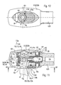
- FIGS. 11 and 12 show a number of exemplary embodiments which may be arranged in combination or in each case individually, wherein identical or comparable parts are provided with the same reference numerals.
- actuating sleeve 92b according to the embodiment of FIG. 7 is provided, which is to move in the direction of the arrow 115a to the rear to release the tool shaft 8, as has been described above.
- a pre-described jack 141 between the tool shaft 8 and the handpiece shaft 25 is provided.
- a securing lug 29b can be provided, which is clamped or prestressed by the force of a spring into a cap 31 or annular groove of the tool shank 8, but independent of a movement of the actuating member 91 out of the calotte 31 or the annular groove is removable or displaceable.
- the securing nose 29b is acted upon by the spring 133 in its securing position, whereby the securing nose 29b can be integrally formed on the spring plate 132 or can be attached to it as a separate component and preferably acted upon directly by the compression spring 133 can be.
- the securing lug 29 b is formed on a prismatic or cylindrical pin 29 c, which is inserted from the front into a hole of the spring plate 132 and at its end facing away from the nose has a flange 29 d, which on the side facing away from the plug hole 27 of the spring plate 132 is applied, preferably on the step surface of a stepped hole.
- the safety catch 29b instead of a convexly rounded shape have inclined surfaces or a frustoconical surface on a nasal stump which only slightly engages in the dome 31 or the annular groove.
- each rearwardly diverging insertion rounding or bevel 143 to classify, whereby the assembly and disassembly of the actuating sleeve 92b is much easier.
- the insertion bevel 143 ensures an automatic compression of the associated stop pin 135, which automatically engages behind the stop 134 in the associated longitudinal groove 137.
- the lead-in bevel 143 terminates over the associated sleeve 138. This makes it possible to disassemble the actuator sleeve 92b with a pointed tool, e.g. a screwdriver, enclosed in the wedge of the insertion bevel 143 and the bushing 138 with the associated stopper pin 135 inserted so far that the actuating sleeve 92 b can be removed.
- this locking device 151 for securing the tool shank 8 in its position accommodated in the holding device 6, this locking device 151 having a securing nose 151b on a latching or securing part 151a fixedly connected to the actuating member 92, here the actuating sleeve 92b is connected and thus with the actuating slide 92 is movable and forms a moving unit.
- This securing lug 151b may be formed by a transverse web on the actuating slide 92, which projects into the plug-in hole 27 or its projection in the standby position or extends secantially thereto and engages in a latching recess 152 in the tool shaft 8, which is an annular groove can.
- the locking lug 151b may be concave-shaped, as seen along the plug-in hole 27, in conformity with the cross-sectional shape of the annular groove bottom, e.g. be rounded so that it is able to embrace the tool shaft 8 sickle-shaped.
- the locking lug 151b opposite the plug recess 94 is extended for the tool shaft 8, so that the actuating slide 92 is displaced into its not shown, here shifted to the right, release position in which the locking lug 151b is moved out of the securing recess 152.
- This latching device 151 which is preferably arranged on the tool side of the handpiece shaft shaft, may be provided instead of or in addition to the latching device 102 and / or 125. It may also be provided the device 116 for pushing out the tool shank 8. In this case, the Moving the operating slide 92 in its release position, the locking lug 151 b pushed out directly from the securing recess 152 and the tool shaft 8 through the wedge surface 117 at the same time.
- the securing lug 151b is formed by a flat disc which is inserted and fixed in a recess 154 which is laterally adjacent to the insertion recess 94, e.g. by gluing or welding.
- the recess 154 may be formed less deep than the thickness of the peripheral wall of the actuating sleeve 92 a, so that a wall portion 92 c remains, on which the disc can rest.
- the handpiece shaft 25 and the parts of the holding device 6 may be made of corrosion-resistant metal and / or plastic.
- the described embodiments also result in an advantageous tool design in the area of a tool shank 8.
- the tool shank 8 has securing recesses which serve for an axial securing and a rotation lock.
- a rotational position adjustment device for the tool 7 can be realized, which allows the arrangement of the tool 7 in different rotational positions.
- an annular groove may be provided in the tool shaft 8 instead of a plurality of dome 131.
- the Verrastungsaus Principleung 152 may be formed in a tool 5, which need not be adjusted in different rotational positions, by a lateral recess. For different rotational positions, an annular recess is particularly well. If a plug-in pin 141a is provided with a non-round cross-section as a rotation lock, the securing recess 152 may be provided in addition to or instead of the caps 31 or an annular groove forming them.
- the inner channel section 13g may terminate within or above one or more working surfaces of the tool 5, and / or the outer longitudinal groove 13h may be provided, which communicate with the supply line extending axially in the handpiece shaft.
- One or two discharge openings 13i formed by branches are shown by way of example in FIG.
- the treatment instrument 1 may be assigned to perform different processing different tools 7, with which it can be optionally equipped.
- tools 7 may be tools 7 of e.g. different shape and / or mass and / or nature of the abrasive work surface, z.
- Different performance requirements may exist for such different tools to achieve optimal performance or performance.
- tools 7 of different masses this may be due to the fact that the mass vibration is particularly favorable for a specific size power setting, e.g. considering vibration resonances.
- a power adjustment of specific size is also advantageous for improving performance.
- the worktops may tend to settle with chips and therefore a specific power setting is also advantageous.
- They may be colored or other markers, e.g. Symbols, each associated with an associated index 155a for positional matching on the adjustment path on the treatment instrument.
- one or more indicia 155 and one or more associated indices 155a may be disposed on the adjusting member 74 and on the gripping sleeve 41 as shown in simplified form, e.g. in the form of a scale, wherein on one part the markings 155 and on the other part of the at least one index 155a is arranged.
- the corresponding marking 156 for example: on the tool shank 8 in the vicinity of the tool head, can be arranged on the tools 7 in each case. Different colors are particularly well suited for distinguishing one marking pair 155, 155a, 156 from another marking pair 155, 155a, 156, wherein mutually corresponding marking rounds 155, 155a, 156 preferably have the same color.
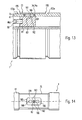
- the adjusting device 73 preferably also has an adjusting element 74 in the form of an adjusting sleeve 74a, which in the FIG correspondingly longer dimensioned groove 75 is axially 29iebar and lockable in the respective setting position by the locking device 83 or in stages.
- the adjusting member 81 is rigidly connected by a radial connecting pin 161 with the adjusting member 74, wherein the connecting pin 161 passes through a longitudinal Einstellnut 162 in the sleeve housing and wherein the longitudinal groove walls 163 clamp the connecting pin 161 so strong between them that the connecting pin is axially displaceable only with a manual force, but is detected against unintentional displacement, however, by the clamping action of the groove walls 163.
- the adjustment groove 162 may be formed in an insert 164 of elastically deformable material, eg plastic, which is seated in a corresponding recess 165 in the sleeve housing 41.
- 163 latching recesses 166 may be arranged in one or both groove walls, in which the connecting pin 161 is able to engage. In the present embodiment, three locking points are arranged axially behind one another. To clarify this, the illustrated longitudinal section of the treatment instrument 1 without the adjusting sleeve 74a is shown in FIG.
- the markings 155, 155a and 156 can be arranged in this embodiment at the front edge or trailing edge of the adjusting member 74 and the lateral surface of the sleeve housing 41 located next to it.
Landscapes
- Health & Medical Sciences (AREA)
- Life Sciences & Earth Sciences (AREA)
- Oral & Maxillofacial Surgery (AREA)
- Veterinary Medicine (AREA)
- Animal Behavior & Ethology (AREA)
- General Health & Medical Sciences (AREA)
- Public Health (AREA)
- Dentistry (AREA)
- Surgery (AREA)
- Epidemiology (AREA)
- Nuclear Medicine, Radiotherapy & Molecular Imaging (AREA)
- Orthopedic Medicine & Surgery (AREA)
- Engineering & Computer Science (AREA)
- Biomedical Technology (AREA)
- Heart & Thoracic Surgery (AREA)
- Medical Informatics (AREA)
- Molecular Biology (AREA)
- Dental Tools And Instruments Or Auxiliary Dental Instruments (AREA)
Claims (9)
- instrument de traitement médical ou dentaire (1) pour le traitement par enlèvement de copeaux d'un tissu corporel ou d'un produit de remplacement à l'aide d'un outil abrasif (7)
composé d'une pièce à main (2) avec un oscillateur (5) et une pièce oscillante (4) logée dans la partie d'extrémité avant de celui-ci et portant l'outil (7), la pièce oscillante pouvant être amenée à osciller par l'oscillateur (5),
dans lequel la pièce à main (2) est reliée ou peut être reliée au niveau de sa partie d'extrémité arrière à une ligne d'alimentation flexible (18) qui s'étend depuis un dispositif d'alimentation,
dans lequel la puissance de l'oscillateur (5) est variable et un dispositif de commande (72) est prévu qui permet d'augmenter ou de diminuer la puissance,
dans lequel un dispositif de réglage (73) disposé dans la pièce à main est prévu avec un élément de réglage (74) à réglage manuel qui agit sur le dispositif de commande (72),
et dans lequel l'oscillateur (5) peut être entraîné ou excité par air comprimé et le dispositif de commande (72) est formé par une vanne-pilote (65), disposée également dans la pièce à main, dont le tiroir de vanne (66) logé de façon mobile commande la dimension d'une ouverture de vanne (67) qui est disposée dans une conduite d'amenée (15b) pour l'air comprimé, s'étendant jusqu'à l'oscillateur (5),
caractérisé en ce que
le tiroir de vanne (66) est sollicité par la pression (p1) appliquée à l'oscillateur (5) contre la force d'un ressort (68) et présente une rampe de commande pour commander la dimension de l'ouverture de vanne (67). - Instrument de traitement médical ou dentaire selon la revendication 1, caractérisé en ce que l'élément de réglage (74) est disposé dans la partie d'extrémité arrière de la pièce à main (2).
- Instrument de traitement médical ou dentaire selon la revendication 2, caractérisé en ce que l'élément de réglage (74) est disposé sur la surface latérale de la pièce à main (2) ou forme la surface latérale et est de préférence ajustable dans la direction circonférentielle.
- Instrument de traitement médical ou dentaire selon la revendication 3, caractérisé en ce que l'élément de réglage (74) est formé par une douille (74a).
- Instrument de traitement médical ou dentaire selon l'une quelconque des revendications précédentes 1 à 4, caractérisé en ce que le dispositif de réglage (73) présente un élément d'ajustage (81) logé de façon mobile dans la pièce à main (2) et relié à l'élément de réglage par l'intermédiaire d'un démultiplicateur.
- Instrument de traitement médical ou dentaire selon l'une quelconque des revendications précédentes 1 à 5, caractérisé en ce que le dispositif de réglage (73) présente un élément d'ajustage (81) logé dans la pièce à main (2) de façon mobile, de préférence de façon axialement mobile, et relié à l'élément de réglage (74) par l'intermédiaire d'un mécanisme qui modifie la direction de déplacement de l'élément d'ajustage (81) par rapport à l'élément de réglage (74).
- Instrument de traitement médical ou dentaire selon l'une quelconque des revendications précédentes, caractérisé en ce qu'à partir de l'élément de réglage (74), une entretoise (76) fait saillie radialement vers l'intérieur à travers une fente (77a) de la douille de préhension (41) et présente une surface inclinée ou courbe (79), de préférence sur sa face arrière ou sa face avant.
- Instrument de traitement médical ou dentaire selon l'une quelconque des revendications précédentes 1 à 7, caractérisé en ce que l'élément de réglage (74) est relié à un élément d'ajustage (81) qui forme une butée pour le ressort (68) de la vanne-pilote (65).
- Instrument de traitement médical ou dentaire selon l'une quelconque des revendications 1 à 8, caractérisé en ce qu'un dispositif de blocage (83) ou un dispositif d'enclenchement (84) à pression manuelle est affecté au dispositif de réglage (73) pour un arrêt dans la position respectivement réglée.
Applications Claiming Priority (7)
| Application Number | Priority Date | Filing Date | Title |
|---|---|---|---|
| DE19716416 | 1997-04-18 | ||
| DE19716416 | 1997-04-18 | ||
| DE19745245A DE19745245A1 (de) | 1997-04-18 | 1997-10-13 | Handstück für medizinische Zwecke insbesondere für eine ärztliche oder zahnärztliche Behandlungseinrichtung, vorzugsweise für eine spanabhebende Bearbeitung eines Zahn-Wurzelkanals |
| DE19745245 | 1997-10-13 | ||
| DE19751584 | 1997-11-21 | ||
| DE19751584A DE19751584A1 (de) | 1997-04-18 | 1997-11-21 | Medizinisches oder dentalmedizinisches Behandlungsinstrument zur spanabhebenden Bearbeitung von Körpergewebe oder einem Ersatzstoff mit einem abrasiven Werkzeug |
| EP98106881A EP0872217B2 (fr) | 1997-04-18 | 1998-04-16 | Instrument médical ou dentaire d'usinage par abrasion de tissus corporels ou d'un matériau de remplacement |
Related Parent Applications (1)
| Application Number | Title | Priority Date | Filing Date |
|---|---|---|---|
| EP98106881A Division EP0872217B2 (fr) | 1997-04-18 | 1998-04-16 | Instrument médical ou dentaire d'usinage par abrasion de tissus corporels ou d'un matériau de remplacement |
Publications (2)
| Publication Number | Publication Date |
|---|---|
| EP1302174A1 EP1302174A1 (fr) | 2003-04-16 |
| EP1302174B1 true EP1302174B1 (fr) | 2006-08-30 |
Family
ID=7827024
Family Applications (1)
| Application Number | Title | Priority Date | Filing Date |
|---|---|---|---|
| EP03001043A Expired - Lifetime EP1302174B1 (fr) | 1997-04-18 | 1998-04-16 | Instrument médical ou dentaire d'usinage par abrasion de tissus corporels ou d'un matériau de remplacement |
Country Status (2)
| Country | Link |
|---|---|
| EP (1) | EP1302174B1 (fr) |
| DE (3) | DE19745245A1 (fr) |
Families Citing this family (1)
| Publication number | Priority date | Publication date | Assignee | Title |
|---|---|---|---|---|
| DE10030114A1 (de) | 2000-06-19 | 2001-12-20 | Kaltenbach & Voigt | Handstück für medizinische Zwecke, insbesondere für eine ärztliche oder zahnärztliche Behandlungseinrichtung, vorzugsweise für eine spanabhebende Bearbeitung eines Zahn-Wurzelkanals |
Citations (1)
| Publication number | Priority date | Publication date | Assignee | Title |
|---|---|---|---|---|
| DE2730137A1 (de) * | 1977-07-04 | 1979-01-25 | Kaltenbach & Voigt | Zahnaerztliches turbinenhandstueck |
Family Cites Families (5)
| Publication number | Priority date | Publication date | Assignee | Title |
|---|---|---|---|---|
| DK125820B (da) * | 1971-03-31 | 1973-05-07 | S Goof | Materialebearbejdningsapparat med elektromagnetisk bevæget arbejdsorgan. |
| US4484893A (en) * | 1983-02-22 | 1984-11-27 | Taco Products, Inc. | Air turbine handpiece for dental scaling and other applications |
| DE3328604A1 (de) | 1983-08-08 | 1985-02-28 | Kaltenbach & Voigt Gmbh & Co, 7950 Biberach | Zahnsteinentfernungs-handstueck |
| FR2613090A1 (fr) * | 1987-03-27 | 1988-09-30 | Micro Mega Sa | Dispositif de reglage d'un debit gazeux |
| DE4439410A1 (de) | 1994-11-04 | 1996-05-09 | Kaltenbach & Voigt | System zur Beseitigung eines Defektes an einem Zahn |
-
1997
- 1997-10-13 DE DE19745245A patent/DE19745245A1/de not_active Withdrawn
-
1998
- 1998-04-16 DE DE59807689T patent/DE59807689D1/de not_active Expired - Lifetime
- 1998-04-16 EP EP03001043A patent/EP1302174B1/fr not_active Expired - Lifetime
- 1998-04-17 DE DE59809008T patent/DE59809008D1/de not_active Expired - Lifetime
Patent Citations (1)
| Publication number | Priority date | Publication date | Assignee | Title |
|---|---|---|---|---|
| DE2730137A1 (de) * | 1977-07-04 | 1979-01-25 | Kaltenbach & Voigt | Zahnaerztliches turbinenhandstueck |
Also Published As
| Publication number | Publication date |
|---|---|
| DE19745245A1 (de) | 1998-10-22 |
| DE59807689D1 (de) | 2003-05-08 |
| DE59809008D1 (de) | 2003-08-21 |
| EP1302174A1 (fr) | 2003-04-16 |
Similar Documents
| Publication | Publication Date | Title |
|---|---|---|
| DE19751682A1 (de) | Medizinisches oder dentalmedizinisches Behandlungsinstrument zur insbesondere spanabhebenden Behandlung von Körpergewebe oder einem Ersatzstoff und Werkzeug für ein solches Behandlungsinstrument | |
| EP0827719B1 (fr) | Instrument médical ou dentaire à laser, en particulier pour le traitement de canaux radiculaires | |
| DE2558064C3 (de) | Zahnärztliche Handstückanordnung | |
| DE19510372C1 (de) | Bohrlehre für chirurgische Bohrwerkzeuge | |
| AT409820B (de) | Medizinisches oder dentalmedizinisches behandlungsinstrument mit einem werkzeugträger in form eines schwingstabes | |
| DE69629895T2 (de) | Schlüsselloser Spannfutter für chirurgisches Blatt | |
| EP0872217B2 (fr) | Instrument médical ou dentaire d'usinage par abrasion de tissus corporels ou d'un matériau de remplacement | |
| AT409821B (de) | Medizinisches oder dentalmedizinisches behandlungsinstrument mit einem insbesondere pneumatischen schwingantrieb | |
| EP0281760A2 (fr) | Système d'accouplement pour outil coupant ayant un manchon | |
| DE102007043837A1 (de) | Rohlinganordnung | |
| DE4439410A1 (de) | System zur Beseitigung eines Defektes an einem Zahn | |
| CH663533A5 (de) | Zahnsteinentfernungs-handstueck. | |
| DE7602659U1 (de) | Handgriff fuer druckluftbetriebene handwerkzeuge | |
| EP0142611A1 (fr) | Outil de perçage pour usiner des surfaces de détalonnage dans des perçages préfabriqués | |
| EP0185163A1 (fr) | Mandrin de perceuse | |
| WO2006050841A1 (fr) | Outils d'ebarbage pour ebarber des trous de faible diametre | |
| DE3530461A1 (de) | Zahnaerztliches handstueck | |
| EP1216009A1 (fr) | Elements a relier par un assemblage a vis, faisant partie notamment d'un instrument medical | |
| DE20204848U1 (de) | Auswechselbare Bohrerspitze und Bohrwerkzeuganordnung | |
| EP0548878A1 (fr) | Dispositif pour l'assemblage précis de deux pièces cylindrique, notamment pour une tige de porte-outil | |
| DE102009040266B4 (de) | Vorrichtung mit einer Aufnahme für ein spanendes Werkzeug | |
| DE69924671T2 (de) | Schneidwerkzeughalter | |
| EP1574170A1 (fr) | Outil ajustable pour l'aide au travail des os | |
| AT405365B (de) | Handstück für ein lasergerät und kupplungsstück für ein handstück eines lasergerätes | |
| AT411567B (de) | Bohrer zur herstellung von bohrungen in einem knochengewebe |
Legal Events
| Date | Code | Title | Description |
|---|---|---|---|
| PUAI | Public reference made under article 153(3) epc to a published international application that has entered the european phase |
Free format text: ORIGINAL CODE: 0009012 |
|
| AC | Divisional application: reference to earlier application |
Ref document number: 0872217 Country of ref document: EP Kind code of ref document: P |
|
| AK | Designated contracting states |
Designated state(s): AT CH DE FR IT LI |
|
| RAP1 | Party data changed (applicant data changed or rights of an application transferred) |
Owner name: KALTENBACH & VOIGT GMBH & CO. KG |
|
| 17P | Request for examination filed |
Effective date: 20030611 |
|
| 17Q | First examination report despatched |
Effective date: 20031030 |
|
| AKX | Designation fees paid |
Designated state(s): AT CH DE FR IT LI |
|
| GRAP | Despatch of communication of intention to grant a patent |
Free format text: ORIGINAL CODE: EPIDOSNIGR1 |
|
| GRAS | Grant fee paid |
Free format text: ORIGINAL CODE: EPIDOSNIGR3 |
|
| GRAA | (expected) grant |
Free format text: ORIGINAL CODE: 0009210 |
|
| RAP1 | Party data changed (applicant data changed or rights of an application transferred) |
Owner name: KALTENBACH & VOIGT GMBH |
|
| AC | Divisional application: reference to earlier application |
Ref document number: 0872217 Country of ref document: EP Kind code of ref document: P |
|
| AK | Designated contracting states |
Kind code of ref document: B1 Designated state(s): AT CH DE FR IT LI |
|
| PG25 | Lapsed in a contracting state [announced via postgrant information from national office to epo] |
Ref country code: IT Free format text: LAPSE BECAUSE OF FAILURE TO SUBMIT A TRANSLATION OF THE DESCRIPTION OR TO PAY THE FEE WITHIN THE PRESCRIBED TIME-LIMIT;WARNING: LAPSES OF ITALIAN PATENTS WITH EFFECTIVE DATE BEFORE 2007 MAY HAVE OCCURRED AT ANY TIME BEFORE 2007. THE CORRECT EFFECTIVE DATE MAY BE DIFFERENT FROM THE ONE RECORDED. Effective date: 20060830 |
|
| REG | Reference to a national code |
Ref country code: CH Ref legal event code: EP Ref country code: CH Ref legal event code: NV Representative=s name: A. BRAUN, BRAUN, HERITIER, ESCHMANN AG PATENTANWAE |
|
| REF | Corresponds to: |
Ref document number: 59813706 Country of ref document: DE Date of ref document: 20061012 Kind code of ref document: P |
|
| ET | Fr: translation filed | ||
| PLBE | No opposition filed within time limit |
Free format text: ORIGINAL CODE: 0009261 |
|
| STAA | Information on the status of an ep patent application or granted ep patent |
Free format text: STATUS: NO OPPOSITION FILED WITHIN TIME LIMIT |
|
| 26N | No opposition filed |
Effective date: 20070531 |
|
| REG | Reference to a national code |
Ref country code: CH Ref legal event code: PFA Owner name: KALTENBACH & VOIGT GMBH Free format text: KALTENBACH & VOIGT GMBH#BISMARCKRING 39#88400 BIBERACH / RISS (DE) -TRANSFER TO- KALTENBACH & VOIGT GMBH#BISMARCKRING 39#88400 BIBERACH / RISS (DE) |
|
| PGFP | Annual fee paid to national office [announced via postgrant information from national office to epo] |
Ref country code: IT Payment date: 20110421 Year of fee payment: 14 |
|
| PG25 | Lapsed in a contracting state [announced via postgrant information from national office to epo] |
Ref country code: IT Free format text: LAPSE BECAUSE OF NON-PAYMENT OF DUE FEES Effective date: 20120416 |
|
| REG | Reference to a national code |
Ref country code: CH Ref legal event code: PCAR Free format text: NEW ADDRESS: HOLBEINSTRASSE 36-38, 4051 BASEL (CH) |
|
| REG | Reference to a national code |
Ref country code: FR Ref legal event code: PLFP Year of fee payment: 18 |
|
| PGFP | Annual fee paid to national office [announced via postgrant information from national office to epo] |
Ref country code: DE Payment date: 20150506 Year of fee payment: 18 Ref country code: CH Payment date: 20150423 Year of fee payment: 18 |
|
| PGFP | Annual fee paid to national office [announced via postgrant information from national office to epo] |
Ref country code: FR Payment date: 20150424 Year of fee payment: 18 Ref country code: AT Payment date: 20150427 Year of fee payment: 18 |
|
| REG | Reference to a national code |
Ref country code: DE Ref legal event code: R119 Ref document number: 59813706 Country of ref document: DE |
|
| REG | Reference to a national code |
Ref country code: CH Ref legal event code: PL |
|
| REG | Reference to a national code |
Ref country code: AT Ref legal event code: MM01 Ref document number: 337744 Country of ref document: AT Kind code of ref document: T Effective date: 20160416 |
|
| REG | Reference to a national code |
Ref country code: FR Ref legal event code: ST Effective date: 20161230 |
|
| PG25 | Lapsed in a contracting state [announced via postgrant information from national office to epo] |
Ref country code: LI Free format text: LAPSE BECAUSE OF NON-PAYMENT OF DUE FEES Effective date: 20160430 Ref country code: FR Free format text: LAPSE BECAUSE OF NON-PAYMENT OF DUE FEES Effective date: 20160502 Ref country code: DE Free format text: LAPSE BECAUSE OF NON-PAYMENT OF DUE FEES Effective date: 20161101 Ref country code: CH Free format text: LAPSE BECAUSE OF NON-PAYMENT OF DUE FEES Effective date: 20160430 |
|
| PG25 | Lapsed in a contracting state [announced via postgrant information from national office to epo] |
Ref country code: AT Free format text: LAPSE BECAUSE OF NON-PAYMENT OF DUE FEES Effective date: 20160416 |