EP1302176A2 - Werkbank für Zahntechniker - Google Patents
Werkbank für Zahntechniker Download PDFInfo
- Publication number
- EP1302176A2 EP1302176A2 EP02022285A EP02022285A EP1302176A2 EP 1302176 A2 EP1302176 A2 EP 1302176A2 EP 02022285 A EP02022285 A EP 02022285A EP 02022285 A EP02022285 A EP 02022285A EP 1302176 A2 EP1302176 A2 EP 1302176A2
- Authority
- EP
- European Patent Office
- Prior art keywords
- workbench
- shaped bracket
- flange
- suction tube
- annular
- Prior art date
- Legal status (The legal status is an assumption and is not a legal conclusion. Google has not performed a legal analysis and makes no representation as to the accuracy of the status listed.)
- Withdrawn
Links
- 230000000284 resting effect Effects 0.000 claims abstract description 24
- 230000008878 coupling Effects 0.000 claims description 6
- 238000010168 coupling process Methods 0.000 claims description 6
- 238000005859 coupling reaction Methods 0.000 claims description 6
- 238000000034 method Methods 0.000 description 3
- 230000036544 posture Effects 0.000 description 2
- 239000000428 dust Substances 0.000 description 1
- 238000012986 modification Methods 0.000 description 1
- 230000004048 modification Effects 0.000 description 1
Images


Classifications
-
- A—HUMAN NECESSITIES
- A61—MEDICAL OR VETERINARY SCIENCE; HYGIENE
- A61C—DENTISTRY; APPARATUS OR METHODS FOR ORAL OR DENTAL HYGIENE
- A61C13/00—Dental prostheses; Making same
- A61C13/12—Tools for fastening artificial teeth; Holders, clamps, or stands for artificial teeth
-
- A—HUMAN NECESSITIES
- A61—MEDICAL OR VETERINARY SCIENCE; HYGIENE
- A61C—DENTISTRY; APPARATUS OR METHODS FOR ORAL OR DENTAL HYGIENE
- A61C19/00—Dental auxiliary appliances
- A61C19/007—Dust removing devices on working places in dental laboratories, e.g. working by suction
Definitions
- the present invention relates to a workbench for dental technicians, particularly adapted for working dental prostheses.
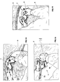
- FIG. 1 An embodiment of the prior art shown in FIG. 1 is provided with a workbench comprising a working table A leaning on a support frame resting on the ground, in which there are at least a sliding drawer C inserted in the frame and a couple of arm resting appendages D connected to the working table and facing the operator sitting in front of the workbench.
- a suction unit E comprising a shaped bracket F in which an opening G is defined communicating with a suction tube M.
- the operator When working according to the teachings of the American and North European Schools, the operator as shown in FIGs. 2 and 3 uses the workbench leaning the arms on the arm resting appendages D while the hands grasping the prosthesis to be worked, are leaning on the working table A in an advanced position relative to the shaped bracket F of the suction unit E.
- the shaped bracket F has the face in which the suction opening G is made, inclined by the angle ⁇ to the working table so as to make easier collection of the dust produced during working of the prosthesis.
- the prosthesis is placed above the suction opening G made in the shaped bracket F which has the upper surface inclined by the angle ⁇ to the operator.
- the two different above described operative modes involve use of different shaped brackets with inclination in mutually opposite directions.
- each workbench must be provided with two different shaped brackets, and each bracket must be removably fixed to the working table and/or the suction tube in order to be easily disassembled and replaced whether the operator decides to work according to one or the other of the two above described modes.
- Another drawback consists in that to shift from one operative mode to the other it is necessary to replace the shaped bracket and remove or apply again the arm resting appendages when passing from one operative mode to the other.
- Another drawback consists also in that by passing from one operative mode to the other, in some cases it is also necessary to modify the height of the shaped bracket to fit its position to the physical characteristics of the operator and more particularly to the length of his arms.
- the present invention aims at overcoming said drawbacks.
- a first object of the invention is to provide a workbench for dental prostheses with a single shaped bracket adapted to be used for both operative modes adopted by the American and North European School or by the Italian School.
- Another object is to provide the workbench of the invention with moving means allowing to adjust the height position of the shaped bracket.
- the suction tube is preferably applied to adjusting means fixed to the workbench frame allowing to move vertically the suction tube and the shaped bracket associated thereto, so that each operator may define the optimal position of the bracket as a function of his needs.
- the rotation of the shaped bracket is allowed by an annular flange associated to the shaped bracket and an annular counter bracket associated to the suction tube that are rotatably coupled to each other one inside the other with a generally bayonet coupling.
- the manipulations allowing the operator to shift from one operative mode to the other are made quicker.
- FIG. 6 The workbench for dental prostheses of the present invention is shown in FIG. 6 where it is generally indicated with 1.
- the workbench comprises a working table 2 leaning on the upper part of a support frame 3 resting on the ground and a couple of arm resting appendages 2a, 2b preferably but necessarily removably applied to the working table 2.
- a suction unit generally indicated with 6 and adapted to collect the working residues of the prosthesis is arranged between the arm resting appendages 2a, 2b and comprises a shaped bracket 7 coupled with a suction tube 8 communicating to the outside by means of a through opening 9 made in the bracket 7.
- the shaped bracket 7 is coupled to the suction tube 8 through connecting means 10 allowing rotation of the shaped bracket 7 along a generally vertical axis Y.
- the connecting means 10 as shown in FIGs. 8 to 12, comprise an annular flange 11 associated to the shaped bracket 7 through screws 11a and an annular counter flange 12 associated to the suction tube 8, which can be rotatably joined to each other one inside the other through coupling means of the bayonet type generally indicated with 13.
- the bayonet coupling means 13 comprise:
- outer diameter 11c of the annular flange 11 is slightly lower than the diameter 12f of the annular counter flange 12 so that the annular flange 11 and the annular counter flange 12 may be mutually coupled by sliding movement.
- the annular flange 11 may freely rotate inside the corresponding annular counter flange 12 and may be blocked in two diametrically opposite positions when the pin 11 a is inserted with an axial movement into the bottom zone 12g, 12h of each transversal channel 12b, 12c.
- the shaped bracket having the upper surface 7a inclined by the angle ⁇ relative to the working table 2 may be arranged inclined either to the operator as shown in FIG. 14 or to the working table as shown in FIG. 15.
- the operator may work according to the method of the Italian School shown in FIG. 14 with the arms leaning on the drawer 5 or according to the method of the American and North European School with the arms leaning on the protruding appendages 2a, 2b of the table 2 as shown in fig 15.
- the shaped flange 7 is also provided with driving means generally indicated with 20 that are adapted to move the flange vertically along the above mentioned axis Y.
- Said driving means 20 comprise a linear guide 21 fixed to the frame 3 and arranged with the longitudinal axis 21a generally vertical and parallel to the axis Y, along which at least a shoe 22 of the ball circulation kind is sliding.
- a motor 23 is also fixed and provided with a pinion gear 24 engaged with a rack 25 fixed to the linear guide 21.
- a bracket 26 is connected to the shoe 22 and supports the suction tube 8 that in its turn supports the shaped flange 7 and the above described corresponding connecting means 10.
- the operator may use the workbench working according to any of the techniques shown in FIGs. 14 and 15, adjusting the height of the bracket 7 according to his needs.
- the workbench 1 of the invention and more particularly the embodiment of the suction unit comprising the shaped bracket 7 and the connecting means 10 to the suction tube 8 equipping the workbench, fully attain the intended objects.
- the shaped bracket 7 may be made with any kind of profile and protection devices may also be applied to it, adapted to avoid throwing of splints to the surrounding environment thus protecting the operator.
Landscapes
- Health & Medical Sciences (AREA)
- Oral & Maxillofacial Surgery (AREA)
- Dentistry (AREA)
- Epidemiology (AREA)
- Life Sciences & Earth Sciences (AREA)
- Animal Behavior & Ethology (AREA)
- General Health & Medical Sciences (AREA)
- Public Health (AREA)
- Veterinary Medicine (AREA)
- Dental Tools And Instruments Or Auxiliary Dental Instruments (AREA)
- Dental Preparations (AREA)
Applications Claiming Priority (2)
| Application Number | Priority Date | Filing Date | Title |
|---|---|---|---|
| ITVI20010209 | 2001-10-10 | ||
| IT2001VI000209A ITVI20010209A1 (it) | 2001-10-10 | 2001-10-10 | Banco da lavoro per odontotecnici |
Publications (2)
| Publication Number | Publication Date |
|---|---|
| EP1302176A2 true EP1302176A2 (de) | 2003-04-16 |
| EP1302176A3 EP1302176A3 (de) | 2003-05-28 |
Family
ID=11461709
Family Applications (1)
| Application Number | Title | Priority Date | Filing Date |
|---|---|---|---|
| EP02022285A Withdrawn EP1302176A3 (de) | 2001-10-10 | 2002-10-07 | Werkbank für Zahntechniker |
Country Status (3)
| Country | Link |
|---|---|
| US (1) | US20030073395A1 (de) |
| EP (1) | EP1302176A3 (de) |
| IT (1) | ITVI20010209A1 (de) |
Cited By (2)
| Publication number | Priority date | Publication date | Assignee | Title |
|---|---|---|---|---|
| CN107855998A (zh) * | 2017-09-27 | 2018-03-30 | 芜湖凯尔电气科技有限公司 | 废旧智能手机拆解台 |
| CN113001495A (zh) * | 2021-03-10 | 2021-06-22 | 机械工业第九设计研究院有限公司 | 一种多功能工具柜 |
Families Citing this family (16)
| Publication number | Priority date | Publication date | Assignee | Title |
|---|---|---|---|---|
| US7857020B2 (en) * | 2004-07-30 | 2010-12-28 | Black & Decker Inc. | Jig apparatus |
| US7434604B2 (en) * | 2004-07-30 | 2008-10-14 | Black & Decker Inc. | Jig apparatus |
| US7455089B2 (en) * | 2004-07-30 | 2008-11-25 | Black & Decker Inc. | Jig apparatus |
| US20070218814A1 (en) * | 2006-02-21 | 2007-09-20 | Schwaiger Barry M | Variable Speed Wet Sharpener And Methods Relating To Same |
| USD569882S1 (en) | 2006-08-22 | 2008-05-27 | Black & Decker Inc. | Miniature variable-spaced finger assembly |
| USD559875S1 (en) | 2006-08-22 | 2008-01-15 | Black & Decker Corporation | Half-blind router bit depth guide |
| USD573615S1 (en) | 2006-08-22 | 2008-07-22 | Black & Decker Inc. | Dust collector |
| USD560235S1 (en) | 2006-08-22 | 2008-01-22 | Black & Decker Corporation | Sliding tapered dovetail and fixed half-blind dovetail template |
| USD577752S1 (en) | 2006-08-22 | 2008-09-30 | Black & Decker Inc. | Jig apparatus |
| USD574864S1 (en) | 2006-08-22 | 2008-08-12 | Black & Decker Inc | Mortise and tenon assembly |
| USD559287S1 (en) | 2006-08-22 | 2008-01-08 | Black & Decker Corporation | Variable-spaced finger assembly |
| USD575312S1 (en) | 2006-08-22 | 2008-08-19 | Black & Decker Inc. | Outrigger for a jig apparatus |
| USD571836S1 (en) | 2006-08-22 | 2008-06-24 | Black & Decker Inc. | Box joint template |
| DE102009044460B3 (de) * | 2009-11-06 | 2011-07-14 | DeguDent GmbH, 63457 | Verfahren zum Heraustrennen eines Formlings aus einem Rohling |
| JP5944250B2 (ja) * | 2012-07-06 | 2016-07-05 | 株式会社モリタ東京製作所 | 歯科技工机 |
| JP5318273B1 (ja) * | 2012-11-16 | 2013-10-16 | 祐子 中島 | 歯科口腔外作業用のフード付簡易吸引トレイ |
Family Cites Families (10)
| Publication number | Priority date | Publication date | Assignee | Title |
|---|---|---|---|---|
| DE7931254U1 (de) * | 1980-02-21 | Strohm + Maier, Labormoebel Gmbh, 7920 Heidenheim | Zahntechnischer Laborarbeitsplatz | |
| CH453250A (it) * | 1965-12-18 | 1968-06-14 | Ziche Mario | Appoggio aspirante per tavolo da lavoro di odontotecnici, orafi od altri |
| DE3328919C1 (de) * | 1983-08-10 | 1984-11-08 | Kaltenbach & Voigt Gmbh & Co, 7950 Biberach | Arbeitstisch |
| DE3339658C1 (de) * | 1983-11-02 | 1985-08-14 | Kaltenbach & Voigt Gmbh & Co, 7950 Biberach | Arbeitsplatz mit Absaugvorrichtung |
| US4824083A (en) * | 1987-01-30 | 1989-04-25 | Officine Augusto Cattani & C. S.P.A. | Work rest, as used in particular by dental technicians and goldsmiths |
| US5033238A (en) * | 1988-05-20 | 1991-07-23 | Kurt Zubler | Dental technician's work station |
| US4936318A (en) * | 1989-05-16 | 1990-06-26 | Schoolman Scientific Corporation | Vacuum barrier |
| US5013240A (en) * | 1990-06-19 | 1991-05-07 | International Equipment & Supply Corp. | Portable dental apparatus |
| US5529533A (en) * | 1991-11-21 | 1996-06-25 | Kantrowitz; Lawrence L. | Removable dental work table with vacuum |
| CA2221584A1 (en) * | 1998-01-22 | 1999-07-22 | Walter Habisreitinger | Focus work support |
-
2001
- 2001-10-10 IT IT2001VI000209A patent/ITVI20010209A1/it unknown
-
2002
- 2002-10-01 US US10/260,538 patent/US20030073395A1/en not_active Abandoned
- 2002-10-07 EP EP02022285A patent/EP1302176A3/de not_active Withdrawn
Non-Patent Citations (1)
| Title |
|---|
| None |
Cited By (2)
| Publication number | Priority date | Publication date | Assignee | Title |
|---|---|---|---|---|
| CN107855998A (zh) * | 2017-09-27 | 2018-03-30 | 芜湖凯尔电气科技有限公司 | 废旧智能手机拆解台 |
| CN113001495A (zh) * | 2021-03-10 | 2021-06-22 | 机械工业第九设计研究院有限公司 | 一种多功能工具柜 |
Also Published As
| Publication number | Publication date |
|---|---|
| EP1302176A3 (de) | 2003-05-28 |
| US20030073395A1 (en) | 2003-04-17 |
| ITVI20010209A1 (it) | 2003-04-10 |
Similar Documents
| Publication | Publication Date | Title |
|---|---|---|
| EP1302176A2 (de) | Werkbank für Zahntechniker | |
| US5393124A (en) | Armrest assembly | |
| CA2568156A1 (fr) | Support d'instruments comprenant une bague et montable sur un endoscope | |
| EP3326752A1 (de) | Verstellbarer hubmechanismus für exzentermaschinen | |
| JP2011240480A (ja) | 3d可変型加工システム | |
| US10981258B2 (en) | Adjustable stroke mechanism for random orbital machine | |
| JPH05269145A (ja) | 手術用顕微鏡の3次元的位置調節の可能な天井懸吊装置 | |
| WO2019003426A1 (ja) | 医療デバイス保持装置及び医療システム | |
| JP6178899B2 (ja) | エルゴノミックな時計業者用の作業ステーション | |
| EP0643568B1 (de) | Haltevorrichtung für einen zahnärztlichen bohrer | |
| KR100978321B1 (ko) | 인공치아 가공용 밀링장치 | |
| CN108838858B (zh) | 一种首饰银材用打磨抛光一体型的加工装置 | |
| CA2000943C (en) | Table with support frame and tabletop and control device for varying the height and inclination of the tabletop | |
| CN217912315U (zh) | 一种办公椅加工用金属骨架弯曲装置 | |
| CN100387406C (zh) | 用于机器人的机器人手臂的驱动装置 | |
| CN218135475U (zh) | 锥齿轮角向定位装置 | |
| JP2000253953A (ja) | ワークステーション | |
| JP4249530B2 (ja) | パラレルメカニズム利用の位置決め装置 | |
| EP0426031A1 (de) | Industrienähmaschine und Tragtisch sowie Steuerungspedal dafür | |
| GB2265637A (en) | Transmission and balancing mechanism for the workpiece supporting arm of a stitching machine | |
| KR200343442Y1 (ko) | 헬스 자전거의 접이 장치 | |
| WO2008127088A2 (en) | Device for height adjustment of a table top such as a working or writing desk | |
| EP0882415B1 (de) | Höheneinstellbare Füsse zum Tragen einer Tisch-, Büro- oder Arbeitsplatte | |
| KR100292779B1 (ko) | 치과용진료장치 | |
| CN219490514U (zh) | 一种无纺布裁切设备 |
Legal Events
| Date | Code | Title | Description |
|---|---|---|---|
| PUAI | Public reference made under article 153(3) epc to a published international application that has entered the european phase |
Free format text: ORIGINAL CODE: 0009012 |
|
| PUAL | Search report despatched |
Free format text: ORIGINAL CODE: 0009013 |
|
| AK | Designated contracting states |
Designated state(s): AT BE BG CH CY CZ DE DK EE ES FI FR GB GR IE IT LI LU MC NL PT SE SK TR |
|
| AX | Request for extension of the european patent |
Extension state: AL LT LV MK RO SI |
|
| AK | Designated contracting states |
Designated state(s): AT BE BG CH CY CZ DE DK EE ES FI FR GB GR IE IT LI LU MC NL PT SE SK TR |
|
| AX | Request for extension of the european patent |
Extension state: AL LT LV MK RO SI |
|
| RIC1 | Information provided on ipc code assigned before grant |
Ipc: 7A 61C 13/12 B Ipc: 7A 61C 13/38 A |
|
| AKX | Designation fees paid | ||
| REG | Reference to a national code |
Ref country code: DE Ref legal event code: 8566 |
|
| STAA | Information on the status of an ep patent application or granted ep patent |
Free format text: STATUS: THE APPLICATION IS DEEMED TO BE WITHDRAWN |
|
| 18D | Application deemed to be withdrawn |
Effective date: 20031129 |