EP1302248A2 - Procédé et dispositif de dépôt par plasma - Google Patents
Procédé et dispositif de dépôt par plasma Download PDFInfo
- Publication number
- EP1302248A2 EP1302248A2 EP03001217A EP03001217A EP1302248A2 EP 1302248 A2 EP1302248 A2 EP 1302248A2 EP 03001217 A EP03001217 A EP 03001217A EP 03001217 A EP03001217 A EP 03001217A EP 1302248 A2 EP1302248 A2 EP 1302248A2
- Authority
- EP
- European Patent Office
- Prior art keywords
- substrate
- plasma
- deposition
- grooves
- substrates
- Prior art date
- Legal status (The legal status is an assumption and is not a legal conclusion. Google has not performed a legal analysis and makes no representation as to the accuracy of the status listed.)
- Withdrawn
Links
Images



Classifications
-
- C—CHEMISTRY; METALLURGY
- C23—COATING METALLIC MATERIAL; COATING MATERIAL WITH METALLIC MATERIAL; CHEMICAL SURFACE TREATMENT; DIFFUSION TREATMENT OF METALLIC MATERIAL; COATING BY VACUUM EVAPORATION, BY SPUTTERING, BY ION IMPLANTATION OR BY CHEMICAL VAPOUR DEPOSITION, IN GENERAL; INHIBITING CORROSION OF METALLIC MATERIAL OR INCRUSTATION IN GENERAL
- C23C—COATING METALLIC MATERIAL; COATING MATERIAL WITH METALLIC MATERIAL; SURFACE TREATMENT OF METALLIC MATERIAL BY DIFFUSION INTO THE SURFACE, BY CHEMICAL CONVERSION OR SUBSTITUTION; COATING BY VACUUM EVAPORATION, BY SPUTTERING, BY ION IMPLANTATION OR BY CHEMICAL VAPOUR DEPOSITION, IN GENERAL
- C23C16/00—Chemical coating by decomposition of gaseous compounds, without leaving reaction products of surface material in the coating, i.e. chemical vapour deposition [CVD] processes
- C23C16/22—Chemical coating by decomposition of gaseous compounds, without leaving reaction products of surface material in the coating, i.e. chemical vapour deposition [CVD] processes characterised by the deposition of inorganic material, other than metallic material
- C23C16/26—Deposition of carbon only
- C23C16/27—Diamond only
- C23C16/276—Diamond only using plasma jets
-
- C—CHEMISTRY; METALLURGY
- C23—COATING METALLIC MATERIAL; COATING MATERIAL WITH METALLIC MATERIAL; CHEMICAL SURFACE TREATMENT; DIFFUSION TREATMENT OF METALLIC MATERIAL; COATING BY VACUUM EVAPORATION, BY SPUTTERING, BY ION IMPLANTATION OR BY CHEMICAL VAPOUR DEPOSITION, IN GENERAL; INHIBITING CORROSION OF METALLIC MATERIAL OR INCRUSTATION IN GENERAL
- C23C—COATING METALLIC MATERIAL; COATING MATERIAL WITH METALLIC MATERIAL; SURFACE TREATMENT OF METALLIC MATERIAL BY DIFFUSION INTO THE SURFACE, BY CHEMICAL CONVERSION OR SUBSTITUTION; COATING BY VACUUM EVAPORATION, BY SPUTTERING, BY ION IMPLANTATION OR BY CHEMICAL VAPOUR DEPOSITION, IN GENERAL
- C23C16/00—Chemical coating by decomposition of gaseous compounds, without leaving reaction products of surface material in the coating, i.e. chemical vapour deposition [CVD] processes
- C23C16/22—Chemical coating by decomposition of gaseous compounds, without leaving reaction products of surface material in the coating, i.e. chemical vapour deposition [CVD] processes characterised by the deposition of inorganic material, other than metallic material
- C23C16/26—Deposition of carbon only
- C23C16/27—Diamond only
-
- C—CHEMISTRY; METALLURGY
- C23—COATING METALLIC MATERIAL; COATING MATERIAL WITH METALLIC MATERIAL; CHEMICAL SURFACE TREATMENT; DIFFUSION TREATMENT OF METALLIC MATERIAL; COATING BY VACUUM EVAPORATION, BY SPUTTERING, BY ION IMPLANTATION OR BY CHEMICAL VAPOUR DEPOSITION, IN GENERAL; INHIBITING CORROSION OF METALLIC MATERIAL OR INCRUSTATION IN GENERAL
- C23C—COATING METALLIC MATERIAL; COATING MATERIAL WITH METALLIC MATERIAL; SURFACE TREATMENT OF METALLIC MATERIAL BY DIFFUSION INTO THE SURFACE, BY CHEMICAL CONVERSION OR SUBSTITUTION; COATING BY VACUUM EVAPORATION, BY SPUTTERING, BY ION IMPLANTATION OR BY CHEMICAL VAPOUR DEPOSITION, IN GENERAL
- C23C16/00—Chemical coating by decomposition of gaseous compounds, without leaving reaction products of surface material in the coating, i.e. chemical vapour deposition [CVD] processes
- C23C16/22—Chemical coating by decomposition of gaseous compounds, without leaving reaction products of surface material in the coating, i.e. chemical vapour deposition [CVD] processes characterised by the deposition of inorganic material, other than metallic material
- C23C16/26—Deposition of carbon only
- C23C16/27—Diamond only
- C23C16/277—Diamond only using other elements in the gas phase besides carbon and hydrogen; using other elements besides carbon, hydrogen and oxygen in case of use of combustion torches; using other elements besides carbon, hydrogen and inert gas in case of use of plasma jets
-
- C—CHEMISTRY; METALLURGY
- C23—COATING METALLIC MATERIAL; COATING MATERIAL WITH METALLIC MATERIAL; CHEMICAL SURFACE TREATMENT; DIFFUSION TREATMENT OF METALLIC MATERIAL; COATING BY VACUUM EVAPORATION, BY SPUTTERING, BY ION IMPLANTATION OR BY CHEMICAL VAPOUR DEPOSITION, IN GENERAL; INHIBITING CORROSION OF METALLIC MATERIAL OR INCRUSTATION IN GENERAL
- C23C—COATING METALLIC MATERIAL; COATING MATERIAL WITH METALLIC MATERIAL; SURFACE TREATMENT OF METALLIC MATERIAL BY DIFFUSION INTO THE SURFACE, BY CHEMICAL CONVERSION OR SUBSTITUTION; COATING BY VACUUM EVAPORATION, BY SPUTTERING, BY ION IMPLANTATION OR BY CHEMICAL VAPOUR DEPOSITION, IN GENERAL
- C23C16/00—Chemical coating by decomposition of gaseous compounds, without leaving reaction products of surface material in the coating, i.e. chemical vapour deposition [CVD] processes
- C23C16/44—Chemical coating by decomposition of gaseous compounds, without leaving reaction products of surface material in the coating, i.e. chemical vapour deposition [CVD] processes characterised by the method of coating
- C23C16/458—Chemical coating by decomposition of gaseous compounds, without leaving reaction products of surface material in the coating, i.e. chemical vapour deposition [CVD] processes characterised by the method of coating characterised by the method used for supporting substrates in the reaction chamber
-
- C—CHEMISTRY; METALLURGY
- C23—COATING METALLIC MATERIAL; COATING MATERIAL WITH METALLIC MATERIAL; CHEMICAL SURFACE TREATMENT; DIFFUSION TREATMENT OF METALLIC MATERIAL; COATING BY VACUUM EVAPORATION, BY SPUTTERING, BY ION IMPLANTATION OR BY CHEMICAL VAPOUR DEPOSITION, IN GENERAL; INHIBITING CORROSION OF METALLIC MATERIAL OR INCRUSTATION IN GENERAL
- C23C—COATING METALLIC MATERIAL; COATING MATERIAL WITH METALLIC MATERIAL; SURFACE TREATMENT OF METALLIC MATERIAL BY DIFFUSION INTO THE SURFACE, BY CHEMICAL CONVERSION OR SUBSTITUTION; COATING BY VACUUM EVAPORATION, BY SPUTTERING, BY ION IMPLANTATION OR BY CHEMICAL VAPOUR DEPOSITION, IN GENERAL
- C23C16/00—Chemical coating by decomposition of gaseous compounds, without leaving reaction products of surface material in the coating, i.e. chemical vapour deposition [CVD] processes
- C23C16/44—Chemical coating by decomposition of gaseous compounds, without leaving reaction products of surface material in the coating, i.e. chemical vapour deposition [CVD] processes characterised by the method of coating
- C23C16/458—Chemical coating by decomposition of gaseous compounds, without leaving reaction products of surface material in the coating, i.e. chemical vapour deposition [CVD] processes characterised by the method of coating characterised by the method used for supporting substrates in the reaction chamber
- C23C16/4582—Rigid and flat substrates, e.g. plates or discs
- C23C16/4583—Rigid and flat substrates, e.g. plates or discs the substrate being supported substantially horizontally
- C23C16/4584—Rigid and flat substrates, e.g. plates or discs the substrate being supported substantially horizontally the substrate being rotated
-
- C—CHEMISTRY; METALLURGY
- C23—COATING METALLIC MATERIAL; COATING MATERIAL WITH METALLIC MATERIAL; CHEMICAL SURFACE TREATMENT; DIFFUSION TREATMENT OF METALLIC MATERIAL; COATING BY VACUUM EVAPORATION, BY SPUTTERING, BY ION IMPLANTATION OR BY CHEMICAL VAPOUR DEPOSITION, IN GENERAL; INHIBITING CORROSION OF METALLIC MATERIAL OR INCRUSTATION IN GENERAL
- C23C—COATING METALLIC MATERIAL; COATING MATERIAL WITH METALLIC MATERIAL; SURFACE TREATMENT OF METALLIC MATERIAL BY DIFFUSION INTO THE SURFACE, BY CHEMICAL CONVERSION OR SUBSTITUTION; COATING BY VACUUM EVAPORATION, BY SPUTTERING, BY ION IMPLANTATION OR BY CHEMICAL VAPOUR DEPOSITION, IN GENERAL
- C23C16/00—Chemical coating by decomposition of gaseous compounds, without leaving reaction products of surface material in the coating, i.e. chemical vapour deposition [CVD] processes
- C23C16/44—Chemical coating by decomposition of gaseous compounds, without leaving reaction products of surface material in the coating, i.e. chemical vapour deposition [CVD] processes characterised by the method of coating
- C23C16/50—Chemical coating by decomposition of gaseous compounds, without leaving reaction products of surface material in the coating, i.e. chemical vapour deposition [CVD] processes characterised by the method of coating using electric discharges
- C23C16/513—Chemical coating by decomposition of gaseous compounds, without leaving reaction products of surface material in the coating, i.e. chemical vapour deposition [CVD] processes characterised by the method of coating using electric discharges using plasma jets
Definitions
- This invention relates to plasma deposition of substances and, more particularly, to plasma deposition on a substrate of films of material such as synthetic diamond by techniques utilizing a plasma jet.
- the cross-section of the plasma beam is generally limited in practical applications, the area on which it is desired to deposit a diamond film may be many times larger than the deposition beam. This means that the beam and the target substrate need to be moved with respect to each other during the deposition process, which gives rise to a number of problems.
- the film will have a temperature gradient associated with power density from the impinging jet, and the film will tend to experience thermal cycling as the substrate moves with respect to the beam. The temperature gradients and/or thermal cycling tend to stress the diamond film, and can cause it to crack or spall off the substrate. Even if the film remains intact on the substrate, it may contain internal stress defects that can render it unacceptable for the purpose for which it was intended.
- US-A-4,292,342 describes a method in which polycrystalline silicon is deposited on the interior surface of a shaped container.
- the silicon is deposited by reacting hydrogen and a silicon bearing gas in the presence of a high pressure plasma.
- the silicon body is separated from the shaped container by utilizing thermal expansion shear stress.
- JP-A-59043861 illustrates a chemical vapour deposition device which expands a uniformally coatable region and has improved workability by holding substrates in the form of a louver with respect to the flow of reacting gas in a reaction chamber.
- the temperature variation of a substrate and a substance being deposited thereon is controlled, both temporally and spatially, by moving the substrate and the deposition beam with respect to each other at a rate which results in no more than a certain maximum temperature variation for specified operating conditions.
- the invention is directed to a method and apparatus for depositing a substance, such as synthetic diamond.
- a plasma beam is produced, and contains the constituents of the substance to be deposited.
- beam is intended to generically include the terms beam and jet.
- a substrate is provided, and has a surface (that is, at least one surface) in the path of the beam, the area of said surface being substantially larger than the cross-sectional area of the beam impinging on the surface.
- Repetitive motion that is, motion in a pattern that substantially repeats
- the substrate, the beam, or both can be moved.
- the substrate can be tilted at a substantial angle (at least 10 degrees) with respect to the plane perpendicular to the beam direction, and the step of repetitively moving the substrate with respect to the beam may comprise moving the substrate back and forth with a component of motion perpendicular to the direction of the beam.
- a rotation rate of at least about 500 rpm is preferred, with substantially higher rates of several thousand rpm being recommended for most situations.
- factors such as the beam energy, the beam and substrate coverage geometries, and the properties of the substrate material all enter into the computation of the velocity (of the substrate and beam with respect to each other) that is necessary to keep temperature variations under control.
- Selection of substrate materials having favorable properties, particularly density and thermodynamic properties, will tend to reduce the velocity needed to attain a particular temperature deviation limit. Copper, tungsten, molybdenum, tungsten carbide, and molybdenum carbide have relatively favorable properties.
- Other attributes which should be taken into account pertain to the compatibility with the substance being deposited, including retention of the substance on the substrate, and the relative coefficients of expansion.
- the substrate in a plasma deposition system is provided with structural attributes that facilitate efficient deposition.
- groups of substrates are arranged with respect to the plasma beam in a manner which also facilitates efficient deposition. Applicant has found that, in addition to increasing the portion of the plasma beam volume which contacts the substrate surface or surfaces, it is advantageous to provide for the efficient evacuation of "spent fluids" (i.e. the remaining parts, mostly gasses, of an elemental volume of plasma which has deposited its operative species on the substrate) away from the substrate so that fresh plasma containing the operative species can easily and continuously contact the substrate surface.
- grooves, apertures, or both are provided in the substrate, and function to channel spent fluids of the plasma beam away from the deposition surface of the substrate to permit more efficient deposition on the substrate by the operative species of the plasma.
- groups of substrates are provided, with openings between the substrates for evacuation of spent fluids.
- a plurality of substrates are provided having surfaces generally along the envelope of the beam such that constituents (or operative species) in the peripheral region of the beam are applied to the surfaces.
- the plasma beam can be divided into a plurality of beam portions, and substrates provided with surfaces along the envelopes of the beam portions. At advancing positions in the beam propagation direction, the surfaces of the substrates can be at successively smaller radial distances from the axis of the beam. In this manner, as the beam is consumed [by deposition, and by evacuation of spent fluids through openings in substrates or between the substrates], the substrates continue to approximately envelop the periphery of a remaining smaller beam.
- Fig. 1 is a diagram, partially in schematic form, of an apparatus in accordance with an embodiment of the invention and which can be utilized to practice an embodiment of the method of the invention.
- Fig. 2 is a diagram, partially broken away, of a portion of the Fig. 1 apparatus in accordance with another embodiment of the invention.
- Fig. 3 illustrates the beam impingement area of the Fig. 2 embodiment.
- Fig. 4 is a diagram, partially in schematic form, of an apparatus which can be utilized to practice another embodiment of the invention.
- Fig. 5 is a diagram of the stand of the Fig. 4 apparatus.
- Fig. 6 is a top view of an embodiment of a substrate in accordance with a form of the invention.
- Fig. 7 is a top view of another embodiment of a substrate in accordance with a form of the invention.
- Fig. 8 is a top view of another embodiment of a substrate in accordance with a form of the invention.
- Fig. 9 is a cross-sectional view of a substrate array in accordance with an embodiment of the invention.
- Fig. 10 is a perspective view of a portion of the substrate array of Fig. 9.
- Fig. 11 is a cross-sectional view of a substrate array in accordance with another embodiment of the invention.
- Fig. 12 is a cross-sectional view of a substrate array in accordance with a further embodiment of the invention.
- Fig. 13 is a bottom view of the substrate array of Fig. 12.
- a deposition chamber 100 is the lower section of a plasma jet deposition system 200, evacuated by one or more vacuum pumping systems (not shown).
- the system 200 is contained within a vacuum housing 211 and includes an arc-forming section 215 which comprises a cylindrical anode 291, a rod-like cathode 292, and an injector 295 mounted adjacent the cathode so as to permit injected fluid to pass over the cathode.
- the input fluid may be, for example, a mixture of hydrogen and methane.
- the methane could alternatively be fed in downstream.
- the anode 291 and cathode 292 are energized by a source of electric potential (not shown), for example a DC potential. Cylindrical magnets, designated by reference numeral 217, are utilized to accelerate and focus the plasma generated at the arc forming section.
- the magnets maintain the plasma within a narrow column until the plasma reaches the deposition region.
- a nozzle represented at 115, can be used to control beam size, within limitations.
- a mixture of hydrogen and methane is fed to the injector 295, and a plasma is obtained in front of the arc forming section and accelerated and focused toward the deposition region.
- synthetic polycrystalline diamond can be formed from the described plasma, as the carbon in the methane is selectively deposited as diamond, and the graphite which forms is dissipated by combination with the hydrogen facilitating gas.
- the deposition chamber 100 contains a substrate holder 120 which is mounted on a shaft 140.
- the holder 120 includes a base 121, and a radiator 123 or other suitable device can be mounted on the base, if necessary or desired.
- a substrate 150 is mounted on the holder 120, such as by retainer bolts (not shown).
- the term "substrate” is intended to mean an object having at least one surface on which a substance is to be deposited. It will be understood that a substrate may only temporarily hold a deposited layer which is intended for subsequent removal from the substrate.
- a substrate may also be an object on which the deposited surface is intended to be permanently affixed; for example, the substrate may be the base of a wear surface of deposited synthetic diamond, such as for ultimate use in a tool.
- the shaft 140 non-concentric with the beam, extends through a vacuum-tight feed-through 160 to a motor 170 which spins the shaft 140, holder 120, and substrate 150 at a desired rate during the deposition process.
- the motor could be located within the vacuum chamber.
- the substrate can be tilted at a substantial angle with respect to the plane perpendicular to the beam direction. This is illustrated in Fig. 2, wherein the substrate 150 is at a substantial angle with respect to the beam 225. [The tilt can be introduced in either the substrate or the beam.]
- the plane of the holder 120 (and the corresponding plane of the substrate 150) is at an angle of about 45 degrees with respect to the plane (illustrated by dashed line 295) that is perpendicular to the direction of beam 225.
- the diameter of beam impingement on the substrate is the square root of 2 times the beam diameter.
- a reciprocating motion (see double-headed arrow 281) can be imparted to the shaft 140 by a reciprocating motor 287 to achieve repetitive coverage on the substrate. If desired, this can be in conjunction with rotating motion imparted to the shaft.
- a component of motion can be introduced in the plasma beam, such as by introducing controlled gas dynamic instabilities.
- FIG. 4 there is shown an embodiment of an apparatus in accordance with a further form of the invention and which can be used to practice an embodiment of a method of the invention.
- the deposition system 200 is generally similar to that of Fig. 1, and like reference numerals represent the same or similar elements.
- the deposition chamber 100 contains a substrate holder in the form of an opened cylindrical stand 420 with legs 421 and an annular base 422 to which a substrate can be secured (see also Fig. 5).
- a temperature controlling device (not shown) or other suitable device can be mounted on the base, if necessary or de ired.
- a substrate 460 is mounted on the holder 420, such as by retainer bolts (not shown).
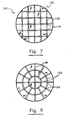
- Fig. 6 shows an embodiment of a substrate 460, which has a deposition surface 165 that is shown as being generally flat and has a pattern of grooves 168 which, in this illustration, are in a two-dimensional grid pattern.
- the grooves preferably have a smooth trough-like contour, although any suitable contour, for example triangular, can be utilized.
- the grooves extend generally across the substrate and to the edges of the substrate surface. The preferred depth of the grooves can depend on the substrate size and the operating conditions, a suggested minimum depth being about 2 mm. In operation, the grooves facilitate deposition by a plasma beam.
- the spent fluids are more readily evacuated from the deposition region by being channeled by the grooves to the edges of the substrate.
- the grooves also serve to divide the substrate area into relatively smaller individual regions. For some applications, this is advantageous in obtaining deposited films that are less likely to break or crack than larger area films.
- Fig. 7 illustrates a substrate having a groove pattern like that of Fig. 6, but with a plurality of apertures 170 through the substrate.
- the apertures are located at the groove intersections.
- Spent fluids are channelled to the apertures as well as to the edges of the substrate.
- the apertures may also serve to equalize pressure conditions over the substrate surface to result in more uniform deposition. It will be understood that one or more apertures can be employed, with or without grooves, if desired. Also, in this and other embodiments, the substrate surface can be curved.
- Fig. 8 illustrates another example of a substrate configuration with grooves and apertures, this embodiment having radial grooves 188, circular grooves 192 intersecting the radial grooves, and apertures 195 at the intersections. It will be understood that other apertures and/or further apertures can be provided which are not in the grooves or not at the groove intersections.
- Fig. 9 illustrates a substrate array in accordance with an embodiment of the invention.
- the array in the deposition chamber 100 includes a number of substrates having surfaces that are generally parallel to the beam direction.
- Substrate surfaces at advancing positions in the beam propagation direction are at successively smaller radial distances from the beam axis.
- the embodiment of Fig. 9 shows four groups of substrates 610, 620, 630 and 640 at four successively smaller radial distances from the beam axis as the beam progresses.
- each group of substrate surfaces has a hexagonal cross-section (two substrates of each group being visible in Fig.
- a perspective view of two adjacent groups (e.g. 630, 640) being illustrated in Fig 10.
- the groups of substrates are shown secured together by brackets 631, 641 and bolts 632, 642.
- the contact between substrates and the brackets help to maintain the group at substantially the same temperature.
- openings 605 Between the groups of substrates are openings 605 through which the spent fluids can progress toward the vacuum pumping system.
- Brackets such as 655 can be used between the respective groups, and other supporting structure (not shown), including a stand of the type shown in Fig. 5, can be used to support the substrate array in the deposition chamber or to secure the array, or portions thereof, to the chamber.
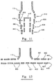
- Fig. 11 is like that of Fig. 10, but also has coaxial groups of substrates 670, 680, 690, with openings therebetween, as before. These can also be in hexagonal or other suitable arrangements.
- a further substrate 675 is shown as being perpendicular to the beam direction and contributes to formation of the beam into a generally annular cross-section, with most of the deposition on the inner surfaces of the substrates of groups 610, 620, 630 and 640, the outer surfaces of the substrates of groups 670, 680 and 690, and the top surface of substrate 675.
- the substrate 675 can be omitted, with resulting co-axial flow around the substrate groups 670, 680 and 690, with deposition on both the inner and outer surfaces of the substrates of these groups.
- supporting structures can be of the types illustrated in Fig.s 5 and 10, or of any suitable type.
- Fig. 12 shows a configuration of substrates in accordance with another embodiment of the invention wherein the plasma beam is formed into a radially propagating beam that is generally enveloped by substrate surfaces.
- the beam leaving the nozzle 115 encounters a "T" that is formed by annular rings of substrates.
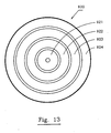
- the bottom set 920 of substrate rings is shown in Fig. 13, and includes annular rings 921, 922, 923 and 924. Ring 921 has a central aperture, and there are openings 805 between the other rings.
- the top set 960 of substrate rings includes annular rings 961 (adjacent nozzle 115) and 962. Again, brackets or other suitable supports (not shown) can be provided.
- any of the substrates in the embodiments of Fig.s 9-13 can have apertures and/or grooves, as described in conjunction with Fig.s 5-8. Also, the substrates, or arrays thereof, can be tilted and/or moved with respect to the beam, as described in conjunction with Fig.s 13.
Landscapes
- Chemical & Material Sciences (AREA)
- Engineering & Computer Science (AREA)
- Mechanical Engineering (AREA)
- Chemical Kinetics & Catalysis (AREA)
- General Chemical & Material Sciences (AREA)
- Materials Engineering (AREA)
- Metallurgy (AREA)
- Organic Chemistry (AREA)
- Physics & Mathematics (AREA)
- Plasma & Fusion (AREA)
- Inorganic Chemistry (AREA)
- Combustion & Propulsion (AREA)
- Chemical Vapour Deposition (AREA)
- Crystals, And After-Treatments Of Crystals (AREA)
Applications Claiming Priority (6)
| Application Number | Priority Date | Filing Date | Title |
|---|---|---|---|
| US07/698,538 US5342660A (en) | 1991-05-10 | 1991-05-10 | Method for plasma jet deposition |
| US07/698,446 US5204144A (en) | 1991-05-10 | 1991-05-10 | Method for plasma deposition on apertured substrates |
| US698446 | 1991-05-10 | ||
| US698538 | 1991-05-10 | ||
| EP99119093A EP0969120B1 (fr) | 1991-05-10 | 1992-05-08 | Procédé de dépôt par plasma |
| EP92911953A EP0583374B1 (fr) | 1991-05-10 | 1992-05-08 | Procede et appareil de deposition par jet de plasma |
Related Parent Applications (1)
| Application Number | Title | Priority Date | Filing Date |
|---|---|---|---|
| EP99119093A Division EP0969120B1 (fr) | 1991-05-10 | 1992-05-08 | Procédé de dépôt par plasma |
Publications (2)
| Publication Number | Publication Date |
|---|---|
| EP1302248A2 true EP1302248A2 (fr) | 2003-04-16 |
| EP1302248A3 EP1302248A3 (fr) | 2003-07-09 |
Family
ID=27106210
Family Applications (3)
| Application Number | Title | Priority Date | Filing Date |
|---|---|---|---|
| EP03001217A Withdrawn EP1302248A3 (fr) | 1991-05-10 | 1992-05-08 | Procédé et dispositif de dépôt par plasma |
| EP92911953A Expired - Lifetime EP0583374B1 (fr) | 1991-05-10 | 1992-05-08 | Procede et appareil de deposition par jet de plasma |
| EP99119093A Expired - Lifetime EP0969120B1 (fr) | 1991-05-10 | 1992-05-08 | Procédé de dépôt par plasma |
Family Applications After (2)
| Application Number | Title | Priority Date | Filing Date |
|---|---|---|---|
| EP92911953A Expired - Lifetime EP0583374B1 (fr) | 1991-05-10 | 1992-05-08 | Procede et appareil de deposition par jet de plasma |
| EP99119093A Expired - Lifetime EP0969120B1 (fr) | 1991-05-10 | 1992-05-08 | Procédé de dépôt par plasma |
Country Status (5)
| Country | Link |
|---|---|
| EP (3) | EP1302248A3 (fr) |
| JP (2) | JP3350929B2 (fr) |
| CA (2) | CA2443497A1 (fr) |
| DE (2) | DE69233144T2 (fr) |
| WO (1) | WO1992020464A1 (fr) |
Families Citing this family (7)
| Publication number | Priority date | Publication date | Assignee | Title |
|---|---|---|---|---|
| DE4437053A1 (de) * | 1994-10-18 | 1996-02-08 | Widia Gmbh | WC-Hartlegierung, Verfahren zu seiner Herstellung und seiner Verwendung |
| US5587207A (en) * | 1994-11-14 | 1996-12-24 | Gorokhovsky; Vladimir I. | Arc assisted CVD coating and sintering method |
| US5753045A (en) * | 1995-01-25 | 1998-05-19 | Balzers Aktiengesellschaft | Vacuum treatment system for homogeneous workpiece processing |
| EP0724026B1 (fr) * | 1995-01-25 | 1999-10-13 | Balzers Aktiengesellschaft | Procédé de dépÔt réactif |
| US5762715A (en) * | 1995-06-07 | 1998-06-09 | Saint-Gobain/Norton Industrial Ceramics Corporation | Segmented substrate for improved ARC-JET diamond deposition |
| CN109371379B (zh) * | 2018-12-03 | 2021-05-11 | 湖南顶立科技有限公司 | 一种沉积装置及制备热解炭的方法 |
| EP4076719A1 (fr) * | 2019-12-20 | 2022-10-26 | Crystaphase Products Inc. | Resaturation de gaz dans un courant d'alimentation en liquide |
Family Cites Families (15)
| Publication number | Priority date | Publication date | Assignee | Title |
|---|---|---|---|---|
| US4261650A (en) * | 1978-12-18 | 1981-04-14 | International Business Machines Corporation | Method for producing uniform parallel alignment in liquid crystal cells |
| US4292342A (en) * | 1980-05-09 | 1981-09-29 | Motorola, Inc. | High pressure plasma deposition of silicon |
| US4487162A (en) * | 1980-11-25 | 1984-12-11 | Cann Gordon L | Magnetoplasmadynamic apparatus for the separation and deposition of materials |
| US4505947A (en) * | 1982-07-14 | 1985-03-19 | The Standard Oil Company (Ohio) | Method for the deposition of coatings upon substrates utilizing a high pressure, non-local thermal equilibrium arc plasma |
| JPS5921026A (ja) * | 1982-07-28 | 1984-02-02 | Hitachi Ltd | 半導体製造装置 |
| JPS5943861A (ja) * | 1982-09-03 | 1984-03-12 | Ulvac Corp | ル−バ−式化学的蒸着装置 |
| DE3422718A1 (de) * | 1984-06-19 | 1986-01-09 | Plasmainvent AG, Zug | Vakuum-plasma-beschichtungsanlage |
| JPS63107898A (ja) * | 1986-10-23 | 1988-05-12 | Natl Inst For Res In Inorg Mater | プラズマを用いるダイヤモンドの合成法 |
| JP2783796B2 (ja) * | 1987-05-22 | 1998-08-06 | キヤノン株式会社 | 堆積膜形成装置及びプラズマ処理装置 |
| JPH01157498A (ja) * | 1987-12-14 | 1989-06-20 | Natl Inst For Res In Inorg Mater | 高温プラズマによるダイヤモンドの製造法 |
| JPH01242141A (ja) * | 1988-03-23 | 1989-09-27 | Hitachi Ltd | 高気圧マイクロ波プラズマ反応装置 |
| JPH01312008A (ja) * | 1988-06-11 | 1989-12-15 | Nkk Corp | 金属間化合物合金材の製造方法 |
| JP2841715B2 (ja) * | 1989-06-21 | 1998-12-24 | 株式会社日本自動車部品総合研究所 | ダイヤモンド膜の製造装置および製造方法 |
| US5094878A (en) * | 1989-06-21 | 1992-03-10 | Nippon Soken, Inc. | Process for forming diamond film |
| JPH0780718B2 (ja) * | 1989-08-04 | 1995-08-30 | トヨタ自動車株式会社 | ダイヤモンドの合成方法および合成装置 |
-
1992
- 1992-05-08 JP JP50018393A patent/JP3350929B2/ja not_active Expired - Fee Related
- 1992-05-08 CA CA002443497A patent/CA2443497A1/fr not_active Abandoned
- 1992-05-08 DE DE1992633144 patent/DE69233144T2/de not_active Expired - Fee Related
- 1992-05-08 EP EP03001217A patent/EP1302248A3/fr not_active Withdrawn
- 1992-05-08 DE DE69231293T patent/DE69231293T2/de not_active Expired - Fee Related
- 1992-05-08 WO PCT/US1992/004035 patent/WO1992020464A1/fr not_active Ceased
- 1992-05-08 EP EP92911953A patent/EP0583374B1/fr not_active Expired - Lifetime
- 1992-05-08 EP EP99119093A patent/EP0969120B1/fr not_active Expired - Lifetime
- 1992-05-08 CA CA002102781A patent/CA2102781C/fr not_active Expired - Fee Related
-
2002
- 2002-07-08 JP JP2002199034A patent/JP3470715B2/ja not_active Expired - Fee Related
Also Published As
| Publication number | Publication date |
|---|---|
| EP0583374A4 (fr) | 1995-05-03 |
| WO1992020464A1 (fr) | 1992-11-26 |
| EP0969120A2 (fr) | 2000-01-05 |
| JPH06510566A (ja) | 1994-11-24 |
| JP3350929B2 (ja) | 2002-11-25 |
| DE69233144D1 (de) | 2003-09-04 |
| DE69231293T2 (de) | 2001-03-15 |
| EP0583374B1 (fr) | 2000-07-26 |
| CA2443497A1 (fr) | 1992-11-26 |
| EP1302248A3 (fr) | 2003-07-09 |
| DE69233144T2 (de) | 2004-05-13 |
| EP0969120A3 (fr) | 2000-04-12 |
| EP0969120B1 (fr) | 2003-07-30 |
| JP2003041373A (ja) | 2003-02-13 |
| JP3470715B2 (ja) | 2003-11-25 |
| EP0583374A1 (fr) | 1994-02-23 |
| CA2102781C (fr) | 2003-11-18 |
| CA2102781A1 (fr) | 1992-11-11 |
| DE69231293D1 (de) | 2000-08-31 |
Similar Documents
| Publication | Publication Date | Title |
|---|---|---|
| US5487787A (en) | Apparatus and method for plasma deposition | |
| US5342660A (en) | Method for plasma jet deposition | |
| US4487162A (en) | Magnetoplasmadynamic apparatus for the separation and deposition of materials | |
| US4471003A (en) | Magnetoplasmadynamic apparatus and process for the separation and deposition of materials | |
| US4440108A (en) | Ion beam coating apparatus | |
| US5811820A (en) | Parallel ion optics and apparatus for high current low energy ion beams | |
| EP0711847A1 (fr) | Méthode et dispositif pour CVD assisté par l'arc | |
| AU2002332200B2 (en) | Method for carrying out homogeneous and heterogeneous chemical reactions using plasma | |
| US4526673A (en) | Coating method | |
| EP0969120B1 (fr) | Procédé de dépôt par plasma | |
| US5310512A (en) | Method for producing synthetic diamond structures | |
| US5902649A (en) | Vacuum treatment system for homogeneous workpiece processing | |
| US6406760B1 (en) | Diamond film deposition on substrate arrays | |
| US4466876A (en) | Thin layer depositing apparatus | |
| CN87107779A (zh) | 徽波增强式化学汽相淀积法及设备 | |
| US6173672B1 (en) | Diamond film deposition on substrate arrays | |
| US6443092B1 (en) | Apparatus for synthesizing diamond film by DC PACVD | |
| JPS6148416A (ja) | 材料の分離および析出の電磁流体力学的装置および方法 | |
| JPS63169386A (ja) | 薄膜形成方法 | |
| JPH073441A (ja) | 立方晶窒化ホウ素被覆方法 |
Legal Events
| Date | Code | Title | Description |
|---|---|---|---|
| PUAI | Public reference made under article 153(3) epc to a published international application that has entered the european phase |
Free format text: ORIGINAL CODE: 0009012 |
|
| 17P | Request for examination filed |
Effective date: 20030124 |
|
| AC | Divisional application: reference to earlier application |
Ref document number: 0969120 Country of ref document: EP Kind code of ref document: P Ref document number: 0583374 Country of ref document: EP Kind code of ref document: P |
|
| AK | Designated contracting states |
Designated state(s): DE FR GB |
|
| PUAL | Search report despatched |
Free format text: ORIGINAL CODE: 0009013 |
|
| AK | Designated contracting states |
Designated state(s): DE FR GB |
|
| AKX | Designation fees paid |
Designated state(s): DE FR GB |
|
| STAA | Information on the status of an ep patent application or granted ep patent |
Free format text: STATUS: THE APPLICATION HAS BEEN WITHDRAWN |
|
| 18W | Application withdrawn |
Effective date: 20041028 |