EP1302255A1 - Presse radiale - Google Patents
Presse radiale Download PDFInfo
- Publication number
- EP1302255A1 EP1302255A1 EP02022544A EP02022544A EP1302255A1 EP 1302255 A1 EP1302255 A1 EP 1302255A1 EP 02022544 A EP02022544 A EP 02022544A EP 02022544 A EP02022544 A EP 02022544A EP 1302255 A1 EP1302255 A1 EP 1302255A1
- Authority
- EP
- European Patent Office
- Prior art keywords
- pressure ring
- press
- radial
- base body
- abutment
- Prior art date
- Legal status (The legal status is an assumption and is not a legal conclusion. Google has not performed a legal analysis and makes no representation as to the accuracy of the status listed.)
- Granted
Links
- 230000009471 action Effects 0.000 claims abstract description 3
- 238000003825 pressing Methods 0.000 claims description 14
- 238000006073 displacement reaction Methods 0.000 claims description 5
- 230000002093 peripheral effect Effects 0.000 claims description 2
- 230000001681 protective effect Effects 0.000 claims description 2
- 230000004323 axial length Effects 0.000 description 5
- 238000013461 design Methods 0.000 description 5
- 238000011161 development Methods 0.000 description 5
- 230000018109 developmental process Effects 0.000 description 5
- 238000010276 construction Methods 0.000 description 4
- 230000002349 favourable effect Effects 0.000 description 4
- 238000003892 spreading Methods 0.000 description 4
- 230000007480 spreading Effects 0.000 description 4
- 238000012545 processing Methods 0.000 description 3
- 238000005253 cladding Methods 0.000 description 2
- 238000009434 installation Methods 0.000 description 2
- 230000010354 integration Effects 0.000 description 2
- 238000004519 manufacturing process Methods 0.000 description 2
- 238000007789 sealing Methods 0.000 description 2
- 125000006850 spacer group Chemical group 0.000 description 2
- 238000012549 training Methods 0.000 description 2
- 230000000052 comparative effect Effects 0.000 description 1
- 230000000295 complement effect Effects 0.000 description 1
- 230000008094 contradictory effect Effects 0.000 description 1
- 230000008878 coupling Effects 0.000 description 1
- 238000010168 coupling process Methods 0.000 description 1
- 238000005859 coupling reaction Methods 0.000 description 1
- 230000002996 emotional effect Effects 0.000 description 1
- 238000005538 encapsulation Methods 0.000 description 1
- 239000012530 fluid Substances 0.000 description 1
- 238000003780 insertion Methods 0.000 description 1
- 230000037431 insertion Effects 0.000 description 1
- 238000012423 maintenance Methods 0.000 description 1
- 239000000463 material Substances 0.000 description 1
- 238000005259 measurement Methods 0.000 description 1
- 239000002184 metal Substances 0.000 description 1
- 238000000034 method Methods 0.000 description 1
- 210000002445 nipple Anatomy 0.000 description 1
- 230000008569 process Effects 0.000 description 1
- 239000007787 solid Substances 0.000 description 1
Images



Classifications
-
- B—PERFORMING OPERATIONS; TRANSPORTING
- B21—MECHANICAL METAL-WORKING WITHOUT ESSENTIALLY REMOVING MATERIAL; PUNCHING METAL
- B21D—WORKING OR PROCESSING OF SHEET METAL OR METAL TUBES, RODS OR PROFILES WITHOUT ESSENTIALLY REMOVING MATERIAL; PUNCHING METAL
- B21D39/00—Application of procedures in order to connect objects or parts, e.g. coating with sheet metal otherwise than by plating; Tube expanders
- B21D39/04—Application of procedures in order to connect objects or parts, e.g. coating with sheet metal otherwise than by plating; Tube expanders of tubes with tubes; of tubes with rods
- B21D39/048—Application of procedures in order to connect objects or parts, e.g. coating with sheet metal otherwise than by plating; Tube expanders of tubes with tubes; of tubes with rods using presses for radially crimping tubular elements
-
- B—PERFORMING OPERATIONS; TRANSPORTING
- B30—PRESSES
- B30B—PRESSES IN GENERAL
- B30B7/00—Presses characterised by a particular arrangement of the pressing members
- B30B7/04—Presses characterised by a particular arrangement of the pressing members wherein pressing is effected in different directions simultaneously or in turn
Definitions
- the present invention relates to a radial press with a basic body, a pressure ring, a solid abutment connected to the base body and one A plurality are arranged concentrically around a press axis Press jaws, the over wedge bevels pressure ring acting on the press jaws under action an annular hydraulic piston-cylinder arrangement along the press axis relative to Basic body is displaceable and the press jaws themselves support guided radially displaceably on the abutment.
- a radial press of the generic type is from the DE 2844475 C2 known.
- this radial press includes the base body has a cylindrical casing and one arranged radially towards the end of this internal flange.
- the pressure ring is on the one hand on a cylindrical inner surface of the housing shell and on the other hand on a cylindrical inner surface of the flange guided sealing; the work space the hydraulic piston-cylinder arrangement is limited by a cylinder surface and an end face of both the base body and also the pressure ring.
- the abutment in the form of a The ring plate is screwed to the housing jacket.
- the radial press in question comprises three firmly with each other via tie rods and spacer sleeves connected plates.
- one of the end plates namely the bottom plate with a breakthrough, is a cone ring inserted on the inner conical Control surface, the press jaws slide smoothly.
- An acting on the press jaws by means of an annular hydraulic piston-cylinder arrangement in axial Movable stamp.
- An axial movement of the stamp - according to the slope of the cone ring - a concentric, conical movement the press jaws.
- EP 239875 B1 describes a radial press with two essentially mirror-symmetrical annular Control bodies, one of which is stationary and the other is movable along the press axis, known.
- the hydraulic drive device exists doing this from two or four hydraulic cylinders that are on the outside of this on the movable control body support, and pistons and piston rods, the at the same time act as a tie rod and firmly with the fixed control body are connected.
- This Radial press affect the outward of that Movable control body protruding hydraulic cylinder the uses of the press. The same applies to the radial press known from DE 3512241 C2.
- the present invention aims to provide a radial press to provide the generic type, which with regard to the requirements set out at the beginning as a particularly practical compromise proves.
- the present aims in particular Invention aims to be a comparatively compact and light radial press of the type specified at the outset to create the high pressures by a high reliability and ease of maintenance distinguished.
- the design of the hydraulic piston-cylinder arrangement such that they are radially outside arranged the tie rods explained above and one immersed in a ring cylinder Ring piston includes, otherwise results in one favorable ratio between the dimensions of the radial press and the possible pressing forces; because by the comparatively large diameter of the hydraulic Piston-cylinder arrangement results in an Large piston surface favorable in terms of the pressing force.
- the reliability of the radial press also benefits from the execution of the invention hydraulic piston-cylinder assembly; because the cylinder is encapsulated so that no dirt can enter can.
- a first preferred development of the invention Radial press is characterized in that the Pressure ring on at least part of the tie rods is guided axially. For example, in this sense in a radial press with eight press jaws and eight tie rods the pressure ring guided on four tie rods his. Such guidance prevents Tilt the pressure ring even if it is in the With regard to the shortest possible axial length the radial press is comparatively short.
- the ring piston the base body and the ring cylinder is assigned to the pressure ring.
- the ring piston can be integral Form part of the basic body and the ring cylinder an integral part of the pressure ring.
- the hydraulic piston-cylinder arrangement can radial presses with special realize compact dimensions.
- the wedge bevels are single-stage executed.
- interchangeable slide bearing plates are provided.
- the radial press according to the invention due to their construction with particularly high, on the Thrust ring acting axial forces can work, so that even with a comparatively steep wedge angle, the at a given axial displacement sufficient pressure stroke of the pressure ring provides the high already mentioned above Let pressing forces be achieved.
- the single level of Wedge bevels on the other hand enable a practical one Integration of plain bearing plates in the area of the wedge bevels, only those within the scope of this Invention possible absence of an outside Interchangeability corresponding housing Plain bearing plates with reasonable installation effort (i.e. without dismantling the press).
- the interchangeable plain bearing plates, which are particularly preferred are just executed and thus a defined Allow surface pressure are both in With regard to the quality and reproducibility of the Press result as well as in terms of life the press particularly cheap.
- Plain bearing plates are preferred not just how explained above, in the area of the wedge bevels provided, but also in the area the sliding surfaces on which the press jaws are radial slidably supported on the abutment. These plain bearing plates can also be preferred without Replace disassembly of the press.
- the end face of the pressure ring acts particularly preferably to a displacement measuring device arranged on the abutment, which with the control of the press communicates. This arrangement of the path measuring device results in a minimization of possible Measurement error.
- Yet another preferred development of the invention is characterized in that with the pressure ring one in a breakthrough of the main body slidable sleeve is connected.
- Such Sleeve provides an additional effective encapsulation of the the interior of the base body receiving the tie rods against the ingress of dirt.
- the sleeve does not even need to be completely closed to be. Rather, according to one again preferred training a recess exhibit; this proves to be particularly favorable when processing pipe bends.
- sleeve can be in corresponding Comparable, functionally similar sealing elements - For example in the form of a telescopically extendable Protective sleeve - insert which ones extend between the pressure ring and the base body.
- the axial displacement causing the press to open the pressure ring can be within the scope of the present Invention are made in different ways.
- a first preferred development of the invention Radial press stands out in this context from that between the thrust ring and the abutment radially outside of the ring cylinder A plurality of return springs is arranged. In consideration comes a single, surrounding the ring cylinder, Return spring designed as a coil spring. By using such mechanical return springs the result is a comparatively simple, inexpensive Construction of the radial press, whereby however part of the hydraulic piston-cylinder arrangement provided force for that Tensioning the return springs is required.
- the design of the radial press is connected in accordance with alternative preferred further training in which opening the press by at least one hydraulic Piston-cylinder unit is effected.
- this Senses can, for example, between the base body and the pressure ring an annular hydraulic work space be provided in the radial direction of a cylindrical peripheral wall of each Basic body and the pressure ring and in the axial direction of one end wall of the base body and of the pressure ring is limited.
- a plurality of hydraulic Piston-cylinder units arranged.
- Such complementary hydraulic piston-cylinder units can not only be used to open the invention Use radial press; rather can they too, if they are double-acting the rapid closing of the press before the start of the Serve force pressing.
- the spreading of the press jaws when opening the press can be accomplished in several ways. In particular can be between two adjacent to each other Pressing jaws acting spreading springs can be provided. Forced coupling is also considered the press jaws with appropriate guides the thrust ring and the abutment, so that every movement of the pressure ring inevitably relative to the abutment leads to a radial movement of the press jaws.
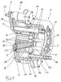
- the radial press assembly illustrated in Figures 1 and 2 comprises a base body 1, a Pressure ring 2, eight concentrically around the press axis 3 pressing jaws 4 arranged around it and an abutment 5.
- the abutment 5 is radial as an annular plate 6 with two protruding connecting lugs 7 executed and over eight aligned parallel to the press axis 3, arranged evenly around the press axis Tie rods 8 firmly connected to the base body 1.
- the tie rods 8 are each on their one end by means of a threaded projection 9 with the Ring plate 6 screwed and on its opposite End by means of the nut 10 on the base body 1 in the area of a radially inward Flange part 11 fixed.
- the press jaws 4 are each arranged between two adjacent tie rods 8.
- the eight tie rods 8 penetrate the pressure ring 2 in corresponding holes 12. There are four of the tie rods 8 and the associated bores 12 of the pressure ring by appropriate dimensioning and Surface processing, possibly by inserting Plain bearing bushes in the pressure ring 2 one on the other voted that the pressure ring on those four Tension rods 8 guided parallel to the press axis 3 becomes.
- the displacement of the pressure ring 2 along the Press axis 3 serves a hydraulic piston-cylinder arrangement, which comprises an annular piston 13, which dips into a ring cylinder 14.
- the Ring piston 13 forms an integral part of the base body 1; the ring cylinder 14 forms in contrast, an integral part of the pressure ring 2.
- the ring piston 14 is by means of two ring seals 15 sealed in the ring cylinder 14.
- the annular hydraulic formed in this way Working space 16 is to be supplied with hydraulic fluid via the bore 17 and the connecting nipple 18 to a pressure medium source connected.
- the eight press jaws 4 each include - in as such known way - a press jaw base 19 and a releasably attachable press jaw replacement part 20.
- the press jaw base body 19 are about guide pieces 21, which by means of Screws 22 are connected to the ring plate 6 and in corresponding guides 23 of the press jaw base body 19 engage radially on the Abutment 5 guided supported.
- the pressure ring 2 and the eight press jaw base bodies 19 lie one above the other corresponding wedge bevels to each other. Both the wedge surfaces 24 of the press jaw base body 19 and the wedge surfaces 25 of the pressure ring 2 just executed. They close with the press axis 3 each a predetermined angle.
- the Wedge surfaces 25 of the pressure ring are interchangeable Plain bearing plates 26 occupied, which each by means the screws 27 are fixed on the pressure ring 2.
- each on the relevant die base 19 support and spreading the Press jaws 4 serve when opening the radial press.
- the pressure ring 2 has a total of eight end faces this introduced relief bores 32, the each between two adjacent, as Bushings for the tie rods 8 serving holes 12 are arranged.
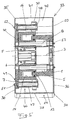
- the one shown in Fig. 3, through a press jaw plane vertical section through a Radial press shows the radial press unit explained above according to Figures 1 and 2 together with one this housing cladding 33.
- the Cover 33 includes a base 34 and one on this attachable and removable hood 35.
- the in the form of an L-shaped sheet metal part executed base part 34 includes a Rear wall 36, a floor 37 and a front wall section 38; it is with one for holding the radial press unit sufficient wall thickness, the main body 1 of the radial press unit in Area of the flange 11 with the rear wall 36 of the Screwed base part 34 and the abutment 5 by means of the cap nut 39, which on the piston rod 31 screwed on the lower piston-cylinder unit 28 is fixed to the front wall section 38.
- the Hood 35 includes a front wall 40, a cover 41 and two side walls 42. It is by means of the cap nut 43, which on the piston rod 31 of the upper Piston-cylinder unit 28 is screwed on, as well the other screw 49 secured in position.
- the front wall 40 and the rear wall 36 of the panel 33 in the area of the press axis 3 for the insertion of Workpieces required breakthroughs in the press intended.
- a sleeve 44 is screwed onto the end face of the pressure ring 2, which in one by the inner circumference of the Flange part 11 defined breakthrough of the base body 1 is guided.
- the sleeve encapsulates the interior of the tie rods 8 I des Base body 1 against the ingress of dirt. It has a recess in its upper area 45 on which the processing of pipe bends with favored narrow curvatures.
- the radial press assembly illustrated in FIG. 4 corresponds in terms of its basic structure the radial press unit according to FIGS. 1 and 2. To avoid repetition, the above explanations for FIGS. 1 to 3 referenced, other than those described below Deviations, also for the radial press unit 4 and the one containing it Radial press according to FIG. 5 apply.
- each return spring 47 is provided in the radial press unit 4 two diametrically opposed to each other Spring units 46 , which one return spring each designed as a coil spring 47 include.
- the return springs 47 extend each between the connecting plate 7 of the abutment 5 and the fastening tab 30 of the pressure ring 2, the return springs 47 each on one screwed to the mounting bracket 30 bearing plate 48 support. As protection against buckling a mandrel 50 is inserted into each of the return springs 47.
- the abutment 5 is by means of the screw 51 on the Front wall section 38 fixed. Securing the position of the Hood 35 on the abutment 5 serves next to the screw 49 the further screw 52.
- the base body 1 by means of the screws 53, which end in the Engage tie rods 8 arranged threaded holes, screwed to the rear wall 36 of the base part 34.
- FIG. 5 The one shown in Fig. 5, through a tie rod plane axial section through a radial press shows the radial press unit according to FIG. 4 together with a cladding 33 enclosing it. 5 is opposite the vertical inclined at 22.5 °; therefore the bottom 37 of the Base part 34 and the openings provided therein 54 for suitable fasteners visible from below.
Landscapes
- Engineering & Computer Science (AREA)
- Mechanical Engineering (AREA)
- Press Drives And Press Lines (AREA)
- Diaphragms And Bellows (AREA)
- Diaphragms For Electromechanical Transducers (AREA)
- Mechanical Treatment Of Semiconductor (AREA)
- Pistons, Piston Rings, And Cylinders (AREA)
- Automatic Assembly (AREA)
Applications Claiming Priority (2)
| Application Number | Priority Date | Filing Date | Title |
|---|---|---|---|
| DE10149924 | 2001-10-10 | ||
| DE10149924A DE10149924A1 (de) | 2001-10-10 | 2001-10-10 | Radialpresse |
Publications (2)
| Publication Number | Publication Date |
|---|---|
| EP1302255A1 true EP1302255A1 (fr) | 2003-04-16 |
| EP1302255B1 EP1302255B1 (fr) | 2004-06-02 |
Family
ID=7702009
Family Applications (1)
| Application Number | Title | Priority Date | Filing Date |
|---|---|---|---|
| EP02022544A Expired - Lifetime EP1302255B1 (fr) | 2001-10-10 | 2002-10-08 | Presse radiale |
Country Status (4)
| Country | Link |
|---|---|
| EP (1) | EP1302255B1 (fr) |
| AT (1) | ATE268232T1 (fr) |
| DE (2) | DE10149924A1 (fr) |
| ES (1) | ES2220867T3 (fr) |
Cited By (7)
| Publication number | Priority date | Publication date | Assignee | Title |
|---|---|---|---|---|
| WO2007093896A1 (fr) * | 2006-02-14 | 2007-08-23 | Eaton Corporation | Appareil de sertissage par replis et procedes de sertissage par replis avec des arretoirs |
| WO2008034132A1 (fr) * | 2006-09-15 | 2008-03-20 | Parker-Hannifin Corporation | Appareil à sertir compact |
| DE102016106650A1 (de) * | 2016-04-12 | 2017-10-12 | Uniflex-Hydraulik Gmbh | Radialpresse |
| DE102020121142A1 (de) | 2020-08-11 | 2022-02-17 | Uniflex - Hydraulik GmbH | Radialpresse |
| WO2022218565A1 (fr) * | 2021-04-12 | 2022-10-20 | Uniflex-Hydraulik Gmbh | Presse radiale |
| EP4144456A1 (fr) | 2021-09-02 | 2023-03-08 | Uniflex-Hydraulik GmbH | Procédé de fabrication d'une conduite hydraulique à haute pression |
| CN115835952A (zh) * | 2020-08-11 | 2023-03-21 | 尤尼弗莱克斯-液压有限责任公司 | 径向压力机 |
Families Citing this family (23)
| Publication number | Priority date | Publication date | Assignee | Title |
|---|---|---|---|---|
| DE102007031482A1 (de) * | 2007-07-06 | 2009-01-08 | Otto Bihler Maschinenfabrik Gmbh & Co Kg | Ringpresse |
| DE102009042442A1 (de) * | 2009-09-22 | 2011-03-31 | Otto Bihler Handels-Beteiligungs-Gmbh | Ringpresse mit hydraulischer Spannringverstellung |
| DE102009042441A1 (de) * | 2009-09-22 | 2011-03-31 | Otto Bihler Handels-Beteiligungs-Gmbh | Ringpresse mit Torque-Motor |
| MX2009012178A (es) * | 2009-11-10 | 2011-05-23 | Ind Regiomontana Quantron S A De C V | Prensa mecanica multipartida para conexiones bridadas con mecanismo de movimiento actuado por cuñas. |
| DE102011015653A1 (de) | 2011-03-31 | 2012-10-04 | Uniflex-Hydraulik Gmbh | Radialpresse |
| DE102011015705B4 (de) | 2011-03-31 | 2023-08-24 | Uniflex-Hydraulik Gmbh | Radialpresse |
| DE102011015706A1 (de) | 2011-03-31 | 2012-10-04 | Uniflex-Hydraulik Gmbh | Radialpresse |
| DE202011004653U1 (de) | 2011-03-31 | 2011-06-09 | Uniflex-Hydraulik GmbH, 61184 | Radialpresse |
| DE102014008613A1 (de) | 2014-06-06 | 2015-12-17 | Uniflex-Hydraulik Gmbh | Radialpresse |
| DE102014012485B3 (de) * | 2014-08-27 | 2015-09-03 | Uniflex-Hydraulik Gmbh | Radialpresse |
| DE202016008097U1 (de) | 2016-02-10 | 2017-02-02 | Uniflex-Hydraulik Gmbh | Radialpresse |
| DE202016100660U1 (de) | 2016-02-10 | 2016-02-17 | Uniflex-Hydraulik Gmbh | Radialpresse |
| DE102017108399B4 (de) | 2017-04-20 | 2019-05-16 | Uniflex-Hydraulik Gmbh | Radialpresse |
| DE102017119403A1 (de) | 2017-08-24 | 2019-02-28 | Uniflex-Hydraulik Gmbh | Radialpressensystem |
| DE202017007489U1 (de) | 2017-08-24 | 2022-02-07 | Uniflex - Hydraulik GmbH | Radialpressensystem |
| DE102018115750B3 (de) | 2018-06-29 | 2019-07-11 | Uniflex-Hydraulik Gmbh | Radialpresse sowie Verfahren zum Fügen zweier Bauteile mittels Radialpressung |
| DE102018115744A1 (de) | 2018-06-29 | 2020-01-02 | Uniflex-Hydraulik Gmbh | Radialpresse sowie Verfahren zum Fügen zweier Bauteile mittels Radialpressung |
| CN113632015B (zh) | 2019-03-29 | 2024-05-28 | 尤尼弗莱克斯-液压有限责任公司 | 用于制造多个复合结构的方法 |
| DE102020125890B3 (de) | 2020-10-02 | 2022-03-10 | Uniflex - Hydraulik GmbH | Radialpresse |
| DE202022102074U1 (de) | 2022-04-19 | 2022-04-27 | Uniflex - Hydraulik GmbH | Radialpresse |
| DE102022109427B4 (de) | 2022-04-19 | 2024-04-25 | Uniflex - Hydraulik GmbH | Radialpresse |
| DE102023109974B3 (de) | 2023-04-20 | 2024-06-20 | Uniflex - Hydraulik GmbH | Radialpresse |
| DE102023119673A1 (de) | 2023-07-25 | 2025-01-30 | Jacob Waitz Industrie GmbH | Verfahren zur Herstellung eines elektrischen oder elektronischen Bauteils |
Citations (4)
| Publication number | Priority date | Publication date | Assignee | Title |
|---|---|---|---|---|
| DE2602781A1 (de) * | 1975-01-27 | 1976-07-29 | Wyle Laboratories | Pressmaschine |
| DE2844475A1 (de) * | 1978-10-12 | 1980-04-24 | Peter Ing Grad Schroeck | Radialpresse fuer werkstuecke mit zylindrischer aussenflaeche mit mehreren, im kreis angeordneten pressbacken |
| EP0239875A2 (fr) * | 1986-04-04 | 1987-10-07 | UNIFLEX-Hydraulik GmbH | Presse radiale |
| EP0298017A2 (fr) * | 1987-06-04 | 1989-01-04 | Erwin Sattler | Presse radiale |
Family Cites Families (1)
| Publication number | Priority date | Publication date | Assignee | Title |
|---|---|---|---|---|
| US4034593A (en) * | 1976-04-09 | 1977-07-12 | The Weatherhead Company | Crimping machine with automatic swing open pushers |
-
2001
- 2001-10-10 DE DE10149924A patent/DE10149924A1/de not_active Withdrawn
-
2002
- 2002-10-08 EP EP02022544A patent/EP1302255B1/fr not_active Expired - Lifetime
- 2002-10-08 ES ES02022544T patent/ES2220867T3/es not_active Expired - Lifetime
- 2002-10-08 AT AT02022544T patent/ATE268232T1/de not_active IP Right Cessation
- 2002-10-08 DE DE50200497T patent/DE50200497D1/de not_active Expired - Lifetime
Patent Citations (4)
| Publication number | Priority date | Publication date | Assignee | Title |
|---|---|---|---|---|
| DE2602781A1 (de) * | 1975-01-27 | 1976-07-29 | Wyle Laboratories | Pressmaschine |
| DE2844475A1 (de) * | 1978-10-12 | 1980-04-24 | Peter Ing Grad Schroeck | Radialpresse fuer werkstuecke mit zylindrischer aussenflaeche mit mehreren, im kreis angeordneten pressbacken |
| EP0239875A2 (fr) * | 1986-04-04 | 1987-10-07 | UNIFLEX-Hydraulik GmbH | Presse radiale |
| EP0298017A2 (fr) * | 1987-06-04 | 1989-01-04 | Erwin Sattler | Presse radiale |
Cited By (17)
| Publication number | Priority date | Publication date | Assignee | Title |
|---|---|---|---|---|
| WO2007093896A1 (fr) * | 2006-02-14 | 2007-08-23 | Eaton Corporation | Appareil de sertissage par replis et procedes de sertissage par replis avec des arretoirs |
| WO2008034132A1 (fr) * | 2006-09-15 | 2008-03-20 | Parker-Hannifin Corporation | Appareil à sertir compact |
| DE102016106650A1 (de) * | 2016-04-12 | 2017-10-12 | Uniflex-Hydraulik Gmbh | Radialpresse |
| WO2017178508A1 (fr) | 2016-04-12 | 2017-10-19 | Uniflex-Hydraulik Gmbh | Presse radiale |
| US11052447B2 (en) * | 2016-04-12 | 2021-07-06 | Uniflex-Hydraulik Gmbh | Radial press |
| DE102016106650B4 (de) | 2016-04-12 | 2021-09-16 | Uniflex-Hydraulik Gmbh | Radialpresse |
| DE102020121142B4 (de) | 2020-08-11 | 2022-03-10 | Uniflex - Hydraulik GmbH | Radialpresse |
| WO2022033819A1 (fr) | 2020-08-11 | 2022-02-17 | Uniflex-Hydraulik Gmbh | Presse radiale |
| DE102020121142A1 (de) | 2020-08-11 | 2022-02-17 | Uniflex - Hydraulik GmbH | Radialpresse |
| CN115835952A (zh) * | 2020-08-11 | 2023-03-21 | 尤尼弗莱克斯-液压有限责任公司 | 径向压力机 |
| CN115916517A (zh) * | 2020-08-11 | 2023-04-04 | 尤尼弗莱克斯-液压有限责任公司 | 径向压力机 |
| US20230114893A1 (en) * | 2020-08-11 | 2023-04-13 | Uniflex-Hydraulik Gmbh | Radial press |
| CN115916517B (zh) * | 2020-08-11 | 2024-07-02 | 尤尼弗莱克斯-液压有限责任公司 | 径向压力机 |
| US12251902B2 (en) | 2020-08-11 | 2025-03-18 | Uniflex-Hydraulik Gmbh | Radial press |
| WO2022218565A1 (fr) * | 2021-04-12 | 2022-10-20 | Uniflex-Hydraulik Gmbh | Presse radiale |
| US11911990B2 (en) | 2021-04-12 | 2024-02-27 | Uniflex-Hydraulik Gmbh | Radial press |
| EP4144456A1 (fr) | 2021-09-02 | 2023-03-08 | Uniflex-Hydraulik GmbH | Procédé de fabrication d'une conduite hydraulique à haute pression |
Also Published As
| Publication number | Publication date |
|---|---|
| ATE268232T1 (de) | 2004-06-15 |
| DE50200497D1 (de) | 2004-07-08 |
| EP1302255B1 (fr) | 2004-06-02 |
| ES2220867T3 (es) | 2004-12-16 |
| DE10149924A1 (de) | 2003-04-30 |
Similar Documents
| Publication | Publication Date | Title |
|---|---|---|
| EP1302255B1 (fr) | Presse radiale | |
| DE3707046C2 (fr) | ||
| DE19940744B4 (de) | Radialpresse | |
| EP0106030B1 (fr) | Machine à cintrer avec mandrin | |
| EP1648625B1 (fr) | Dispositif de laminage | |
| DE10118664A1 (de) | Spanneinrichtung für Gegenstände, insbesondere für zu bearbeitende Werkstücke | |
| DE4409029C2 (de) | Hydraulische Presse | |
| DE19817882A1 (de) | Radialpresse | |
| DE3442446C2 (fr) | ||
| DE3235040A1 (de) | Presse zum aufpressen von huelsen, kabelschuhen oder dergleichen | |
| DE3017025A1 (de) | Hochdruckpresse | |
| DE10339004B4 (de) | Hydraulische Presse | |
| DE3512241A1 (de) | Radialpresse | |
| EP1494827B1 (fr) | Dispositif de deformation plastique de pieces a usiner | |
| DE3008049A1 (de) | Vorrichtung zur stossdaempfung an einer presse | |
| EP1050685B1 (fr) | Glisseur hydraulique linéaire | |
| DE29824688U1 (de) | Radialpresse | |
| EP1073556B1 (fr) | Presse radiale | |
| EP1113954B1 (fr) | Systeme pour permettre l'appui d'une caisse sur un chassis | |
| DE4135014A1 (de) | Presse mit schnittschlagdaempfung | |
| EP1731246B1 (fr) | Appareil pour la fabrication d'une diversité des objets moulés de poudre. | |
| DE102021109039A1 (de) | Radialpresse | |
| DE3426997C2 (de) | Hochdruck-Hubkolbenmaschine | |
| DE3534319A1 (de) | Mehrstufen-schmiedepresse | |
| DE3933079C1 (en) | Forge press cylinder maintenance - with piston rod end pushed into cylinder to give access to piston rod seals |
Legal Events
| Date | Code | Title | Description |
|---|---|---|---|
| PUAI | Public reference made under article 153(3) epc to a published international application that has entered the european phase |
Free format text: ORIGINAL CODE: 0009012 |
|
| AK | Designated contracting states |
Designated state(s): AT BE BG CH CY CZ DE DK EE ES FI FR GB GR IE IT LI LU MC NL PT SE SK TR |
|
| AX | Request for extension of the european patent |
Extension state: AL LT LV MK RO SI |
|
| 17P | Request for examination filed |
Effective date: 20030305 |
|
| GRAP | Despatch of communication of intention to grant a patent |
Free format text: ORIGINAL CODE: EPIDOSNIGR1 |
|
| AKX | Designation fees paid |
Designated state(s): AT BE BG CH CY CZ DE DK EE ES FI FR GB GR IE IT LI LU MC NL PT SE SK TR |
|
| RIN1 | Information on inventor provided before grant (corrected) |
Inventor name: VIEHL, REINER Inventor name: ERTL, FRITZ, DR.-ING. |
|
| GRAA | (expected) grant |
Free format text: ORIGINAL CODE: 0009210 |
|
| GRAS | Grant fee paid |
Free format text: ORIGINAL CODE: EPIDOSNIGR3 |
|
| AK | Designated contracting states |
Kind code of ref document: B1 Designated state(s): AT BE BG CH CY CZ DE DK EE ES FI FR GB GR IE IT LI LU MC NL PT SE SK TR |
|
| PG25 | Lapsed in a contracting state [announced via postgrant information from national office to epo] |
Ref country code: CZ Free format text: LAPSE BECAUSE OF FAILURE TO SUBMIT A TRANSLATION OF THE DESCRIPTION OR TO PAY THE FEE WITHIN THE PRESCRIBED TIME-LIMIT Effective date: 20040602 Ref country code: EE Free format text: LAPSE BECAUSE OF FAILURE TO SUBMIT A TRANSLATION OF THE DESCRIPTION OR TO PAY THE FEE WITHIN THE PRESCRIBED TIME-LIMIT Effective date: 20040602 Ref country code: TR Free format text: LAPSE BECAUSE OF FAILURE TO SUBMIT A TRANSLATION OF THE DESCRIPTION OR TO PAY THE FEE WITHIN THE PRESCRIBED TIME-LIMIT Effective date: 20040602 Ref country code: CY Free format text: LAPSE BECAUSE OF FAILURE TO SUBMIT A TRANSLATION OF THE DESCRIPTION OR TO PAY THE FEE WITHIN THE PRESCRIBED TIME-LIMIT Effective date: 20040602 Ref country code: SK Free format text: LAPSE BECAUSE OF FAILURE TO SUBMIT A TRANSLATION OF THE DESCRIPTION OR TO PAY THE FEE WITHIN THE PRESCRIBED TIME-LIMIT Effective date: 20040602 Ref country code: IE Free format text: LAPSE BECAUSE OF FAILURE TO SUBMIT A TRANSLATION OF THE DESCRIPTION OR TO PAY THE FEE WITHIN THE PRESCRIBED TIME-LIMIT Effective date: 20040602 Ref country code: NL Free format text: LAPSE BECAUSE OF FAILURE TO SUBMIT A TRANSLATION OF THE DESCRIPTION OR TO PAY THE FEE WITHIN THE PRESCRIBED TIME-LIMIT Effective date: 20040602 Ref country code: BG Free format text: LAPSE BECAUSE OF FAILURE TO SUBMIT A TRANSLATION OF THE DESCRIPTION OR TO PAY THE FEE WITHIN THE PRESCRIBED TIME-LIMIT Effective date: 20040602 |
|
| REG | Reference to a national code |
Ref country code: GB Ref legal event code: FG4D Free format text: NOT ENGLISH |
|
| REG | Reference to a national code |
Ref country code: CH Ref legal event code: NV Representative=s name: ISLER & PEDRAZZINI AG Ref country code: CH Ref legal event code: EP |
|
| GBT | Gb: translation of ep patent filed (gb section 77(6)(a)/1977) |
Effective date: 20040602 |
|
| REF | Corresponds to: |
Ref document number: 50200497 Country of ref document: DE Date of ref document: 20040708 Kind code of ref document: P |
|
| REG | Reference to a national code |
Ref country code: IE Ref legal event code: FG4D Free format text: GERMAN |
|
| PG25 | Lapsed in a contracting state [announced via postgrant information from national office to epo] |
Ref country code: SE Free format text: LAPSE BECAUSE OF FAILURE TO SUBMIT A TRANSLATION OF THE DESCRIPTION OR TO PAY THE FEE WITHIN THE PRESCRIBED TIME-LIMIT Effective date: 20040902 Ref country code: DK Free format text: LAPSE BECAUSE OF FAILURE TO SUBMIT A TRANSLATION OF THE DESCRIPTION OR TO PAY THE FEE WITHIN THE PRESCRIBED TIME-LIMIT Effective date: 20040902 Ref country code: GR Free format text: LAPSE BECAUSE OF FAILURE TO SUBMIT A TRANSLATION OF THE DESCRIPTION OR TO PAY THE FEE WITHIN THE PRESCRIBED TIME-LIMIT Effective date: 20040902 |
|
| PG25 | Lapsed in a contracting state [announced via postgrant information from national office to epo] |
Ref country code: LU Free format text: LAPSE BECAUSE OF NON-PAYMENT OF DUE FEES Effective date: 20041008 |
|
| PG25 | Lapsed in a contracting state [announced via postgrant information from national office to epo] |
Ref country code: MC Free format text: LAPSE BECAUSE OF NON-PAYMENT OF DUE FEES Effective date: 20041031 Ref country code: BE Free format text: LAPSE BECAUSE OF NON-PAYMENT OF DUE FEES Effective date: 20041031 |
|
| NLV1 | Nl: lapsed or annulled due to failure to fulfill the requirements of art. 29p and 29m of the patents act | ||
| REG | Reference to a national code |
Ref country code: ES Ref legal event code: FG2A Ref document number: 2220867 Country of ref document: ES Kind code of ref document: T3 |
|
| ET | Fr: translation filed | ||
| REG | Reference to a national code |
Ref country code: IE Ref legal event code: FD4D |
|
| PLBE | No opposition filed within time limit |
Free format text: ORIGINAL CODE: 0009261 |
|
| STAA | Information on the status of an ep patent application or granted ep patent |
Free format text: STATUS: NO OPPOSITION FILED WITHIN TIME LIMIT |
|
| BERE | Be: lapsed |
Owner name: UNIFLEX-HYDRAULIK G.M.B.H. Effective date: 20041031 |
|
| 26N | No opposition filed |
Effective date: 20050303 |
|
| REG | Reference to a national code |
Ref country code: CH Ref legal event code: PCAR Free format text: ISLER & PEDRAZZINI AG;POSTFACH 1772;8027 ZUERICH (CH) |
|
| BERE | Be: lapsed |
Owner name: *UNIFLEX-HYDRAULIK G.M.B.H. Effective date: 20041031 |
|
| PG25 | Lapsed in a contracting state [announced via postgrant information from national office to epo] |
Ref country code: PT Free format text: LAPSE BECAUSE OF NON-PAYMENT OF DUE FEES Effective date: 20041102 |
|
| PGFP | Annual fee paid to national office [announced via postgrant information from national office to epo] |
Ref country code: AT Payment date: 20091022 Year of fee payment: 8 Ref country code: CH Payment date: 20091026 Year of fee payment: 8 |
|
| REG | Reference to a national code |
Ref country code: CH Ref legal event code: PL |
|
| PG25 | Lapsed in a contracting state [announced via postgrant information from national office to epo] |
Ref country code: LI Free format text: LAPSE BECAUSE OF NON-PAYMENT OF DUE FEES Effective date: 20101031 Ref country code: CH Free format text: LAPSE BECAUSE OF NON-PAYMENT OF DUE FEES Effective date: 20101031 |
|
| PG25 | Lapsed in a contracting state [announced via postgrant information from national office to epo] |
Ref country code: AT Free format text: LAPSE BECAUSE OF NON-PAYMENT OF DUE FEES Effective date: 20101008 |
|
| REG | Reference to a national code |
Ref country code: FR Ref legal event code: PLFP Year of fee payment: 14 |
|
| PGFP | Annual fee paid to national office [announced via postgrant information from national office to epo] |
Ref country code: FI Payment date: 20151022 Year of fee payment: 14 Ref country code: GB Payment date: 20151026 Year of fee payment: 14 Ref country code: IT Payment date: 20151026 Year of fee payment: 14 |
|
| PGFP | Annual fee paid to national office [announced via postgrant information from national office to epo] |
Ref country code: FR Payment date: 20151026 Year of fee payment: 14 Ref country code: ES Payment date: 20151023 Year of fee payment: 14 |
|
| PGFP | Annual fee paid to national office [announced via postgrant information from national office to epo] |
Ref country code: DE Payment date: 20151223 Year of fee payment: 14 |
|
| REG | Reference to a national code |
Ref country code: DE Ref legal event code: R119 Ref document number: 50200497 Country of ref document: DE |
|
| GBPC | Gb: european patent ceased through non-payment of renewal fee |
Effective date: 20161008 |
|
| REG | Reference to a national code |
Ref country code: FR Ref legal event code: ST Effective date: 20170630 |
|
| PG25 | Lapsed in a contracting state [announced via postgrant information from national office to epo] |
Ref country code: DE Free format text: LAPSE BECAUSE OF NON-PAYMENT OF DUE FEES Effective date: 20170503 Ref country code: GB Free format text: LAPSE BECAUSE OF NON-PAYMENT OF DUE FEES Effective date: 20161008 Ref country code: FI Free format text: LAPSE BECAUSE OF NON-PAYMENT OF DUE FEES Effective date: 20161008 Ref country code: FR Free format text: LAPSE BECAUSE OF NON-PAYMENT OF DUE FEES Effective date: 20161102 |
|
| PG25 | Lapsed in a contracting state [announced via postgrant information from national office to epo] |
Ref country code: IT Free format text: LAPSE BECAUSE OF NON-PAYMENT OF DUE FEES Effective date: 20161008 |
|
| PG25 | Lapsed in a contracting state [announced via postgrant information from national office to epo] |
Ref country code: ES Free format text: LAPSE BECAUSE OF FAILURE TO SUBMIT A TRANSLATION OF THE DESCRIPTION OR TO PAY THE FEE WITHIN THE PRESCRIBED TIME-LIMIT Effective date: 20040602 |
|
| REG | Reference to a national code |
Ref country code: ES Ref legal event code: FD2A Effective date: 20181122 |
|
| RIC2 | Information provided on ipc code assigned after grant |
Ipc: B30B 7/04 20060101ALI20030122BHEP Ipc: B21D 39/04 20060101AFI20030122BHEP |
|
| PG25 | Lapsed in a contracting state [announced via postgrant information from national office to epo] |
Ref country code: ES Free format text: LAPSE BECAUSE OF FAILURE TO SUBMIT A TRANSLATION OF THE DESCRIPTION OR TO PAY THE FEE WITHIN THE PRESCRIBED TIME-LIMIT Effective date: 20161009 |