EP1302377B1 - Kuppelvorrichtung für ein nicht selbständig angetriebenes Transportmittel - Google Patents
Kuppelvorrichtung für ein nicht selbständig angetriebenes Transportmittel Download PDFInfo
- Publication number
- EP1302377B1 EP1302377B1 EP02079265A EP02079265A EP1302377B1 EP 1302377 B1 EP1302377 B1 EP 1302377B1 EP 02079265 A EP02079265 A EP 02079265A EP 02079265 A EP02079265 A EP 02079265A EP 1302377 B1 EP1302377 B1 EP 1302377B1
- Authority
- EP
- European Patent Office
- Prior art keywords
- frame
- trailer
- coupling
- transport means
- coupling device
- Prior art date
- Legal status (The legal status is an assumption and is not a legal conclusion. Google has not performed a legal analysis and makes no representation as to the accuracy of the status listed.)
- Expired - Lifetime
Links
- 230000008878 coupling Effects 0.000 title claims abstract description 68
- 238000010168 coupling process Methods 0.000 title claims abstract description 68
- 238000005859 coupling reaction Methods 0.000 title claims abstract description 68
- 230000007423 decrease Effects 0.000 claims description 2
- 230000003068 static effect Effects 0.000 description 4
- 230000004048 modification Effects 0.000 description 3
- 238000012986 modification Methods 0.000 description 3
- 230000008901 benefit Effects 0.000 description 1
- 238000010276 construction Methods 0.000 description 1
- 230000002349 favourable effect Effects 0.000 description 1
- 230000006872 improvement Effects 0.000 description 1
- 230000007246 mechanism Effects 0.000 description 1
- 239000000725 suspension Substances 0.000 description 1
Images
Classifications
-
- B—PERFORMING OPERATIONS; TRANSPORTING
- B60—VEHICLES IN GENERAL
- B60T—VEHICLE BRAKE CONTROL SYSTEMS OR PARTS THEREOF; BRAKE CONTROL SYSTEMS OR PARTS THEREOF, IN GENERAL; ARRANGEMENT OF BRAKING ELEMENTS ON VEHICLES IN GENERAL; PORTABLE DEVICES FOR PREVENTING UNWANTED MOVEMENT OF VEHICLES; VEHICLE MODIFICATIONS TO FACILITATE COOLING OF BRAKES
- B60T13/00—Transmitting braking action from initiating means to ultimate brake actuator with power assistance or drive; Brake systems incorporating such transmitting means, e.g. air-pressure brake systems
- B60T13/02—Transmitting braking action from initiating means to ultimate brake actuator with power assistance or drive; Brake systems incorporating such transmitting means, e.g. air-pressure brake systems with mechanical assistance or drive
- B60T13/06—Transmitting braking action from initiating means to ultimate brake actuator with power assistance or drive; Brake systems incorporating such transmitting means, e.g. air-pressure brake systems with mechanical assistance or drive by inertia, e.g. flywheel
- B60T13/08—Overrun brakes
-
- B—PERFORMING OPERATIONS; TRANSPORTING
- B60—VEHICLES IN GENERAL
- B60T—VEHICLE BRAKE CONTROL SYSTEMS OR PARTS THEREOF; BRAKE CONTROL SYSTEMS OR PARTS THEREOF, IN GENERAL; ARRANGEMENT OF BRAKING ELEMENTS ON VEHICLES IN GENERAL; PORTABLE DEVICES FOR PREVENTING UNWANTED MOVEMENT OF VEHICLES; VEHICLE MODIFICATIONS TO FACILITATE COOLING OF BRAKES
- B60T11/00—Transmitting braking action from initiating means to ultimate brake actuator without power assistance or drive or where such assistance or drive is irrelevant
- B60T11/10—Transmitting braking action from initiating means to ultimate brake actuator without power assistance or drive or where such assistance or drive is irrelevant transmitting by fluid means, e.g. hydraulic
- B60T11/107—Transmitting braking action from initiating means to ultimate brake actuator without power assistance or drive or where such assistance or drive is irrelevant transmitting by fluid means, e.g. hydraulic overrun brakes with fluid means
-
- B—PERFORMING OPERATIONS; TRANSPORTING
- B60—VEHICLES IN GENERAL
- B60T—VEHICLE BRAKE CONTROL SYSTEMS OR PARTS THEREOF; BRAKE CONTROL SYSTEMS OR PARTS THEREOF, IN GENERAL; ARRANGEMENT OF BRAKING ELEMENTS ON VEHICLES IN GENERAL; PORTABLE DEVICES FOR PREVENTING UNWANTED MOVEMENT OF VEHICLES; VEHICLE MODIFICATIONS TO FACILITATE COOLING OF BRAKES
- B60T7/00—Brake-action initiating means
- B60T7/12—Brake-action initiating means for automatic initiation; for initiation not subject to will of driver or passenger
- B60T7/20—Brake-action initiating means for automatic initiation; for initiation not subject to will of driver or passenger specially for trailers, e.g. in case of uncoupling of or overrunning by trailer
Definitions
- the invention relates to a coupling device for coupling a non-autonomously driven transport means to a tractive device.
- a non-autonomously driven transport means is a semi-trailer coupled to a motor vehicle, designated as truck, suitable for this purpose.
- a coupling device for coupling a semi-trailer to a truck is generally known.
- the known coupling device comprises a coupling table which is mounted on the truck and which bears a platform which is pivotable about a transverse axis and which is provided on its rearwardly directed side with a widening, wedge-shaped opening.
- the semi-trailer is provided on its underside with a so-called coupling plate for supporting on the platform of the coupling table, and with a downward directed pin, the so-called kingpin, which for the purpose of coupling is received in the wedge-shaped opening of the coupling table and can be secured in the narrowest part thereof.
- Hydraulic or pneumatic systems are generally applied to operate the brakes of a semi-trailer.
- Application of a hydraulic braking system in a hydraulically braked semi-trailer implies intervention in the hydraulic braking system of the semi-trailer, which can cause uncertainties about the division between warranty obligation and liability of truck manufacturer and semi-trailer manufacturer. In practice the permission of the manufacturer of the truck is required for application of a hydraulic braking system on the semi-trailer.
- Application of a pneumatic braking system in a hydraulically braked truck implies a modification of the truck, inter alia by building in a compressor and arranging a number of control valves and lines.
- EP 0 157 336 A2 discloses a coupling device comprising first frame mountable on a tractive device, a second frame which is mountable on the first frame and which is rotatable about a rotation axis perpendicular to the longitudinal and transverse direction of the tractive device, and a coupling shaft which is connected to the transport means and oriented in transverse direction thereof and which is coupled to the second frame in a manner such that it is displaceable through a determined distance relative to the second frame in transverse direction perpendicularly of said rotation axis, said coupling device being provided with operating means for a braking device.
- a further object is to reduce the weight of the combination of a non-autonomously driven transport means and a tractive device.
- a coupling device can be mounted on a truck without any modification in the construction of this truck being required for this purpose.
- a semi-trailer coupled to a truck is rotatable in a plane parallel to the longitudinal and transverse direction of this semi-trailer about the rotation axis of the rotatable frame of the coupling device, whereby the semi-trailer can follow the truck in bends, and is pivotable on the coupling shaft, whereby the semi-trailer can follow the truck on sloping road sections without friction thereby occurring in the coupling device.
- the fact that the coupling shaft is displaceable through a determined distance enables the use of a so-called overrun brake in a semi-trailer.
- An operating lever coupled to a brake cable provides the advantage that a transport means coupled to a tractive device can be provided with a mechanically operated braking system, so that it is not necessary to provide a truck with a compressor, or to make modifications in the hydraulic braking system of a truck.
- the coupling shaft is coupled to the frame by means of roller bearings.
- the coupling shaft is preferably enclosed in its longitudinal direction between enclosing elements connected releasably to the transport means.
- the first and the second frame comprise co-acting parts of a rotating assembly.
- the coupling device according to the invention can likewise be applied for coupling a transport means formed by the fixed part of a trailer to a tractive device formed by the bogie of this trailer.
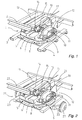
- Fig. 1 shows a coupling device 1 for coupling a semi-trailer, of which a part of chassis 2 is shown, to a truck (not shown).
- Coupling device 1 comprises a subframe 3 which can be fixed at standardized positions on the frame of a truck using shoes 4, and on which the static part 6 of a rotating assembly is fixed by means of bolts 5.
- Fixed on the rotatable part 7 of this rotating assembly is a plate 8 on which roller holders 10 are fixed using mounting pins 9.
- Sub-frame 3 and the static part 6 of the rotating assembly together form a first frame.
- the rotatable part 7 of the rotating assembly, plate 8 and roller holders 10 together form a second frame, which is rotatable about a rotation axis perpendicular to the longitudinal and transverse direction of the truck.
- a coupling shaft 11 which is mounted on trailer chassis 2 and which is displaceable along the length of these roller holders 10 by means of roller bearings 12.
- Coupling shaft 11 is enclosed in its longitudinal direction by wearing plates 13 connected releasably to trailer chassis 2.
- the figure further shows a system of hingedly coupled arms 14, 15, a first arm 14 of which is hingedly coupled to trailer chassis 2 and (by means of a second arm 15) to plate 8 of the rotatable frame, and functions as lever 14, which is furthermore coupled hingedly to a brake cable 16.
- Brake cable 16 is pulled tight in a situation where the truck brakes and the semi-trailer overruns due to its linear momentum, i.e. displaces in forward direction (to bottom left in the figure) relative to the truck, wherein coupling shaft 11 is pressed by means of its roller bearings 12 in forward direction in roller holders 10, wherein brake lever 14, held fixedly at one end by arm 15, is pulled forward at its other end by trailer chassis 2, as a result of which the brake cable 16 is pulled and the overrun of the semi-trailer is braked.
- a damper 17 of a per se known type is built in between trailer chassis 2 and plate 8 of the rotatable frame.
- Fig. 2 shows a coupling device 21 for coupling a trailer, of which a part of chassis 22 is shown, to the bogie of a trailer, of which a part of chassis 23 with wheel suspension 25 and brake drums 27 is shown, wherein the bogie is coupled to a tractive vehicle using a per se known pole.
- Coupling device 21 comprises the static part 6 of a rotating assembly which is fixed on bogie frame 23 by means of bolts 5, and the rotatable part 7 of this rotating assembly, onto which is fixed a plate 8 on which roller holders 10 are fixed using mounting pins 9.
- the static part 6 of the rotating assembly forms a first frame.
- the rotatable part 7 of the rotating assembly, plate 8 and roller holders 10 together form a second frame rotatable about a rotation axis perpendicular to the longitudinal and transverse direction of the bogie.
- a coupling shaft 11 which is mounted on trailer chassis 22 and which is displaceable along the length of these roller holders 10 by means of roller bearings 12.
- Coupling shaft 11 is enclosed in its longitudinal direction by wearing plates 13 connected releasably to trailer chassis 22.
- the figure further shows a lever 14 which is coupled hingedly to trailer chassis 22 and which is coupled to plate 8 of the rotatable frame by means of a brake cable 26 leading to the front wheels of the trailer, and which is further coupled hingedly to a brake cable 16 leading to the rear wheels of the trailer.
- Brake cables 16, 26 are pulled tight in a situation where the bogie brakes, and the trailer overruns due to its linear momentum, i.e. displaces in forward direction relative to the bogie, wherein coupling shaft 11 is pressed by means of its roller bearings 12 in forward direction in roller holders 10, wherein brake lever 14, held fast at one end as soon as brake cable 26 for the front wheels is pulled tight, is pulled forward at its other end by trailer chassis 22, as a result of which the brake cable for the rear wheels 16 is pulled tight and overrunning of the trailer is braked.
- a damper 17 of a per se known type is built in between trailer chassis 2 and plate 8 of the rotatable frame.
- the travel comfort of a vehicle pulling a trailer provided with a coupling device according to the invention is greatly enhanced relative to the comfort in a vehicle pulling a trailer provided with a known coupling device and a control for an overrun brake built into the pole.
- the brakes of the trailer are activated simultaneously at the moment that the trailer overruns, i.e. presses with its full mass against the tractive vehicle.
- the brakes of the front wheels are already activated at the moment before the trailer presses with its full mass against the tractive vehicle, this being perceived by the driver of the tractive vehicle as an significant improvement in the travel comfort.
Landscapes
- Engineering & Computer Science (AREA)
- Transportation (AREA)
- Mechanical Engineering (AREA)
- Physics & Mathematics (AREA)
- Fluid Mechanics (AREA)
- Regulating Braking Force (AREA)
- Platform Screen Doors And Railroad Systems (AREA)
- Agricultural Machines (AREA)
- Braking Arrangements (AREA)
- Devices For Conveying Motion By Means Of Endless Flexible Members (AREA)
- Surgical Instruments (AREA)
- Quick-Acting Or Multi-Walled Pipe Joints (AREA)
Claims (6)
- Kuppelvorrichtung (1, 21) zum Kuppeln eines nicht autonom angetriebenen Transportmittels an eine Zugvorrichtung, umfassendein auf eine Zugvorrichtung montierbares erstes Gestell (3, 6),ein auf das erste (3, 6) Gestell montierbares zweites Gestell (7, 8, 10), das um eine Rotationsachse senkrecht auf der Längs- und Querrichtung der Zugvorrichtung rotierbar ist, undeine mit dem Transportmittel verbundene in Querrichtung dazu ausgerichtete Kuppelwelle (11), welche mit dem zweiten Gestell (7, 8, 10) in einer derartigen Weise gekoppelt ist, dass diese gegenüber dem zweiten Gestell (7, 8, 10) über eine bestimmte Distanz in transversaler Richtung senkrecht zu der genannten Rotationsachse verschiebbar ist, welche Kuppelvorrichtung (1, 21) mit Bedienungsmitteln (14) für eine Bremsvorrichtung versehen ist, dadurch gekennzeichnet, dass die Bedienungsmittel einen scharnierbar an dem Transportmittel und an dem zweiten Gestell (7, 8, 10) gekoppelten Hebel (14) enthalten, welcher Hebel (14) weiter scharnierbar mit einem Bremskabel (16, 26) verbunden ist, auf eine derartige Weise, dass bei der Verschiebung des Transportmittels gegenüber dem zweiten Gestell (7, 8, 10) bei sich verringernder Distanz zwischen dem Transportmittel und dem zweiten Gestell (7, 8, 10) das Bremskabel (16, 26) durch den Hebel (14) angezogen wird.
- Kuppelvorrichtung (1, 21) nach Anspruch 1, dadurch gekennzeichnet, dass die Kuppelwelle (11) mittels Rollenlager (12) an das zweite Gestell (10) gekoppelt ist.
- Kuppelvorrichtung (1, 21) nach einem der Ansprüche 1-2, dadurch gekennzeichnet, dass die Kuppelwelle (11) in ihrer Längsrichtung zwischen lösbar mit dem Transportmittel verbundenen Sicherungselementen (13) eingeschlossen ist.
- Kuppelvorrichtung (1, 21) nach einem der Ansprüche 1-3, dadurch gekennzeichnet, dass das erste und das zweite Gestell zusammenarbeitende Teile eines Drehkranzes (6, 7) enthalten.
- Kuppelvorrichtung (1, 21) nach einem der Ansprüche 1-4, wobei das Transportmittel ein Sattelauflieger ist und die Zugvorrichtung ein Kraftfahrzeug ist.
- Kuppelvorrichtung (1, 21) nach einem der Ansprüche 1-5, wobei das Transportmittel der feste Teil eines Anhängers ist und die Zugvorrichtung das Drehgestell dieses Anhängers ist.
Applications Claiming Priority (2)
| Application Number | Priority Date | Filing Date | Title |
|---|---|---|---|
| NL1019172A NL1019172C2 (nl) | 2001-10-15 | 2001-10-15 | Koppelinrichting voor een niet zelfstandig aangedreven transportmiddel. |
| NL1019172 | 2001-10-15 |
Publications (2)
| Publication Number | Publication Date |
|---|---|
| EP1302377A1 EP1302377A1 (de) | 2003-04-16 |
| EP1302377B1 true EP1302377B1 (de) | 2009-10-21 |
Family
ID=19774172
Family Applications (1)
| Application Number | Title | Priority Date | Filing Date |
|---|---|---|---|
| EP02079265A Expired - Lifetime EP1302377B1 (de) | 2001-10-15 | 2002-10-15 | Kuppelvorrichtung für ein nicht selbständig angetriebenes Transportmittel |
Country Status (4)
| Country | Link |
|---|---|
| EP (1) | EP1302377B1 (de) |
| AT (1) | ATE446226T1 (de) |
| DE (1) | DE60234075D1 (de) |
| NL (1) | NL1019172C2 (de) |
Families Citing this family (1)
| Publication number | Priority date | Publication date | Assignee | Title |
|---|---|---|---|---|
| NO325547B1 (no) * | 2006-03-27 | 2008-06-16 | Sinvent As | Påløpsbrems for semihenger |
Family Cites Families (5)
| Publication number | Priority date | Publication date | Assignee | Title |
|---|---|---|---|---|
| EP0157336A3 (de) * | 1984-03-29 | 1986-10-08 | Weinmann Nutzfahrzeuge GmbH | Auflaufbremse für einen Sattelanhänger |
| DE3502150A1 (de) * | 1985-01-23 | 1986-07-24 | FUHRMANN-Nutzfahrzeuge GmbH, 8266 Erharting | Auflieger-sattelfahrzeug |
| GB8905251D0 (en) * | 1989-03-08 | 1989-04-19 | Lucas Ind Plc | Improvements in braking systems for articulated vehicles |
| DE4325612A1 (de) * | 1993-07-30 | 1995-02-02 | Eggenmueller Alfred | Auflaufbremse für Sattelanhänger |
| DE29909700U1 (de) * | 1999-06-02 | 2000-10-12 | CD Car Development GmbH, 81929 München | Fahrzeuggespann aus Zugfahrzeug und Aufliegeranhänger |
-
2001
- 2001-10-15 NL NL1019172A patent/NL1019172C2/nl not_active IP Right Cessation
-
2002
- 2002-10-15 DE DE60234075T patent/DE60234075D1/de not_active Expired - Lifetime
- 2002-10-15 AT AT02079265T patent/ATE446226T1/de not_active IP Right Cessation
- 2002-10-15 EP EP02079265A patent/EP1302377B1/de not_active Expired - Lifetime
Also Published As
| Publication number | Publication date |
|---|---|
| DE60234075D1 (de) | 2009-12-03 |
| EP1302377A1 (de) | 2003-04-16 |
| ATE446226T1 (de) | 2009-11-15 |
| NL1019172C2 (nl) | 2003-04-18 |
Similar Documents
| Publication | Publication Date | Title |
|---|---|---|
| US6505714B1 (en) | Parking-braking in vehicles | |
| US4795002A (en) | Electrically operated actuator for rear parking brake cables including driver and driven members rotatably mounted about same pivot pin | |
| US3860081A (en) | Drive system for motor vehicles, particularly for truck-trailer and truck semi-trailer combinations | |
| HU193631B (en) | Multiple-axle articulated motor vehicle particularly articulated bus | |
| CN117465869B (zh) | 一种重载移动台车 | |
| EP1302377A1 (de) | Kuppelvorrichtung für ein nicht selbständig angetriebenes Transportmittel | |
| KR101853452B1 (ko) | 수동식 유압 브레이크를 갖는 레일용 운송수단 | |
| US5752587A (en) | Auxiliary braking system | |
| US20090071768A1 (en) | Mechanical Disc Braking Assembly | |
| US5119912A (en) | Automatic/mechanical apply park brake distributor | |
| US7000996B2 (en) | Diagonal parking brake activation for vehicles with plural axles | |
| US2877858A (en) | Vehicle of the full trailer type | |
| CA2068144A1 (en) | Apparatus and method for braking a vehicle | |
| GB2278900A (en) | Hydraulic trailer brake | |
| EP0906857A3 (de) | Verfahren und Vorrichtung zur Nutz- und Reibungsbremsung | |
| CN2259334Y (zh) | 农用车双回路制动装置 | |
| DE3705911C2 (de) | Druckluft-Bremsanlage für Nutzfahrzeuge | |
| CZ2024316A3 (cs) | Přídavná parkovací brzda, způsob k jejímu provozování a vozidlo obsahující tuto brzdu | |
| KR100290651B1 (ko) | 재크 나이프 방지장치 | |
| JPH0231335Y2 (de) | ||
| CA2375803A1 (en) | Vehicle combination consisting of a towing vehicle and a semitrailer | |
| IE870652L (en) | Drive system for commercial motor vehicles. | |
| US3494447A (en) | Friction vehicle braking equipment | |
| WO2003006287A1 (en) | Over-run auto-reverse hydraulic braking system on a trailer | |
| US20250003461A1 (en) | Braking system with balanced actuation |
Legal Events
| Date | Code | Title | Description |
|---|---|---|---|
| PUAI | Public reference made under article 153(3) epc to a published international application that has entered the european phase |
Free format text: ORIGINAL CODE: 0009012 |
|
| AK | Designated contracting states |
Designated state(s): AT BE BG CH CY CZ DE DK EE ES FI FR GB GR IE IT LI LU MC NL PT SE SK TR |
|
| AX | Request for extension of the european patent |
Extension state: AL LT LV MK RO SI |
|
| 17P | Request for examination filed |
Effective date: 20031015 |
|
| AKX | Designation fees paid |
Designated state(s): AT BE BG CH CY CZ DE DK EE ES FI FR GB GR IE IT LI LU MC NL PT SE SK TR |
|
| 17Q | First examination report despatched |
Effective date: 20080908 |
|
| GRAP | Despatch of communication of intention to grant a patent |
Free format text: ORIGINAL CODE: EPIDOSNIGR1 |
|
| GRAS | Grant fee paid |
Free format text: ORIGINAL CODE: EPIDOSNIGR3 |
|
| GRAA | (expected) grant |
Free format text: ORIGINAL CODE: 0009210 |
|
| AK | Designated contracting states |
Kind code of ref document: B1 Designated state(s): AT BE BG CH CY CZ DE DK EE ES FI FR GB GR IE IT LI LU MC NL PT SE SK TR |
|
| REG | Reference to a national code |
Ref country code: GB Ref legal event code: FG4D |
|
| REG | Reference to a national code |
Ref country code: CH Ref legal event code: EP |
|
| REG | Reference to a national code |
Ref country code: IE Ref legal event code: FG4D |
|
| REF | Corresponds to: |
Ref document number: 60234075 Country of ref document: DE Date of ref document: 20091203 Kind code of ref document: P |
|
| REG | Reference to a national code |
Ref country code: SE Ref legal event code: TRGR |
|
| PG25 | Lapsed in a contracting state [announced via postgrant information from national office to epo] |
Ref country code: PT Free format text: LAPSE BECAUSE OF FAILURE TO SUBMIT A TRANSLATION OF THE DESCRIPTION OR TO PAY THE FEE WITHIN THE PRESCRIBED TIME-LIMIT Effective date: 20100222 Ref country code: FI Free format text: LAPSE BECAUSE OF FAILURE TO SUBMIT A TRANSLATION OF THE DESCRIPTION OR TO PAY THE FEE WITHIN THE PRESCRIBED TIME-LIMIT Effective date: 20091021 Ref country code: ES Free format text: LAPSE BECAUSE OF FAILURE TO SUBMIT A TRANSLATION OF THE DESCRIPTION OR TO PAY THE FEE WITHIN THE PRESCRIBED TIME-LIMIT Effective date: 20100201 |
|
| PG25 | Lapsed in a contracting state [announced via postgrant information from national office to epo] |
Ref country code: AT Free format text: LAPSE BECAUSE OF FAILURE TO SUBMIT A TRANSLATION OF THE DESCRIPTION OR TO PAY THE FEE WITHIN THE PRESCRIBED TIME-LIMIT Effective date: 20091021 |
|
| PG25 | Lapsed in a contracting state [announced via postgrant information from national office to epo] |
Ref country code: EE Free format text: LAPSE BECAUSE OF FAILURE TO SUBMIT A TRANSLATION OF THE DESCRIPTION OR TO PAY THE FEE WITHIN THE PRESCRIBED TIME-LIMIT Effective date: 20091021 Ref country code: BG Free format text: LAPSE BECAUSE OF FAILURE TO SUBMIT A TRANSLATION OF THE DESCRIPTION OR TO PAY THE FEE WITHIN THE PRESCRIBED TIME-LIMIT Effective date: 20100121 Ref country code: DK Free format text: LAPSE BECAUSE OF FAILURE TO SUBMIT A TRANSLATION OF THE DESCRIPTION OR TO PAY THE FEE WITHIN THE PRESCRIBED TIME-LIMIT Effective date: 20091021 |
|
| PLBE | No opposition filed within time limit |
Free format text: ORIGINAL CODE: 0009261 |
|
| STAA | Information on the status of an ep patent application or granted ep patent |
Free format text: STATUS: NO OPPOSITION FILED WITHIN TIME LIMIT |
|
| PG25 | Lapsed in a contracting state [announced via postgrant information from national office to epo] |
Ref country code: CZ Free format text: LAPSE BECAUSE OF FAILURE TO SUBMIT A TRANSLATION OF THE DESCRIPTION OR TO PAY THE FEE WITHIN THE PRESCRIBED TIME-LIMIT Effective date: 20091021 Ref country code: SK Free format text: LAPSE BECAUSE OF FAILURE TO SUBMIT A TRANSLATION OF THE DESCRIPTION OR TO PAY THE FEE WITHIN THE PRESCRIBED TIME-LIMIT Effective date: 20091021 |
|
| 26N | No opposition filed |
Effective date: 20100722 |
|
| PG25 | Lapsed in a contracting state [announced via postgrant information from national office to epo] |
Ref country code: GR Free format text: LAPSE BECAUSE OF FAILURE TO SUBMIT A TRANSLATION OF THE DESCRIPTION OR TO PAY THE FEE WITHIN THE PRESCRIBED TIME-LIMIT Effective date: 20100122 |
|
| PG25 | Lapsed in a contracting state [announced via postgrant information from national office to epo] |
Ref country code: IT Free format text: LAPSE BECAUSE OF FAILURE TO SUBMIT A TRANSLATION OF THE DESCRIPTION OR TO PAY THE FEE WITHIN THE PRESCRIBED TIME-LIMIT Effective date: 20091021 |
|
| PG25 | Lapsed in a contracting state [announced via postgrant information from national office to epo] |
Ref country code: MC Free format text: LAPSE BECAUSE OF NON-PAYMENT OF DUE FEES Effective date: 20101031 |
|
| REG | Reference to a national code |
Ref country code: CH Ref legal event code: PL |
|
| PG25 | Lapsed in a contracting state [announced via postgrant information from national office to epo] |
Ref country code: CH Free format text: LAPSE BECAUSE OF NON-PAYMENT OF DUE FEES Effective date: 20101031 Ref country code: LI Free format text: LAPSE BECAUSE OF NON-PAYMENT OF DUE FEES Effective date: 20101031 |
|
| PG25 | Lapsed in a contracting state [announced via postgrant information from national office to epo] |
Ref country code: CY Free format text: LAPSE BECAUSE OF FAILURE TO SUBMIT A TRANSLATION OF THE DESCRIPTION OR TO PAY THE FEE WITHIN THE PRESCRIBED TIME-LIMIT Effective date: 20091021 |
|
| PG25 | Lapsed in a contracting state [announced via postgrant information from national office to epo] |
Ref country code: LU Free format text: LAPSE BECAUSE OF NON-PAYMENT OF DUE FEES Effective date: 20101015 |
|
| PG25 | Lapsed in a contracting state [announced via postgrant information from national office to epo] |
Ref country code: TR Free format text: LAPSE BECAUSE OF FAILURE TO SUBMIT A TRANSLATION OF THE DESCRIPTION OR TO PAY THE FEE WITHIN THE PRESCRIBED TIME-LIMIT Effective date: 20091021 |
|
| PGFP | Annual fee paid to national office [announced via postgrant information from national office to epo] |
Ref country code: IE Payment date: 20121024 Year of fee payment: 11 Ref country code: FR Payment date: 20121031 Year of fee payment: 11 Ref country code: DE Payment date: 20121017 Year of fee payment: 11 Ref country code: BE Payment date: 20121031 Year of fee payment: 11 |
|
| PGFP | Annual fee paid to national office [announced via postgrant information from national office to epo] |
Ref country code: GB Payment date: 20121024 Year of fee payment: 11 Ref country code: SE Payment date: 20121024 Year of fee payment: 11 |
|
| PGFP | Annual fee paid to national office [announced via postgrant information from national office to epo] |
Ref country code: NL Payment date: 20121005 Year of fee payment: 11 |
|
| BERE | Be: lapsed |
Owner name: TRIAS TRANSPORTWERKTUIGENINDUSTRIE B.V. Effective date: 20131031 |
|
| REG | Reference to a national code |
Ref country code: NL Ref legal event code: V1 Effective date: 20140501 |
|
| REG | Reference to a national code |
Ref country code: SE Ref legal event code: EUG |
|
| GBPC | Gb: european patent ceased through non-payment of renewal fee |
Effective date: 20131015 |
|
| REG | Reference to a national code |
Ref country code: DE Ref legal event code: R119 Ref document number: 60234075 Country of ref document: DE Effective date: 20140501 |
|
| REG | Reference to a national code |
Ref country code: IE Ref legal event code: MM4A |
|
| PG25 | Lapsed in a contracting state [announced via postgrant information from national office to epo] |
Ref country code: GB Free format text: LAPSE BECAUSE OF NON-PAYMENT OF DUE FEES Effective date: 20131015 |
|
| REG | Reference to a national code |
Ref country code: FR Ref legal event code: ST Effective date: 20140630 |
|
| PG25 | Lapsed in a contracting state [announced via postgrant information from national office to epo] |
Ref country code: NL Free format text: LAPSE BECAUSE OF NON-PAYMENT OF DUE FEES Effective date: 20140501 Ref country code: DE Free format text: LAPSE BECAUSE OF NON-PAYMENT OF DUE FEES Effective date: 20140501 Ref country code: SE Free format text: LAPSE BECAUSE OF NON-PAYMENT OF DUE FEES Effective date: 20131016 Ref country code: FR Free format text: LAPSE BECAUSE OF NON-PAYMENT OF DUE FEES Effective date: 20131031 |
|
| PG25 | Lapsed in a contracting state [announced via postgrant information from national office to epo] |
Ref country code: BE Free format text: LAPSE BECAUSE OF NON-PAYMENT OF DUE FEES Effective date: 20131031 |
|
| PG25 | Lapsed in a contracting state [announced via postgrant information from national office to epo] |
Ref country code: IE Free format text: LAPSE BECAUSE OF NON-PAYMENT OF DUE FEES Effective date: 20131015 |