EP1302425A2 - Banknote stacking apparatus - Google Patents
Banknote stacking apparatus Download PDFInfo
- Publication number
- EP1302425A2 EP1302425A2 EP02079953A EP02079953A EP1302425A2 EP 1302425 A2 EP1302425 A2 EP 1302425A2 EP 02079953 A EP02079953 A EP 02079953A EP 02079953 A EP02079953 A EP 02079953A EP 1302425 A2 EP1302425 A2 EP 1302425A2
- Authority
- EP
- European Patent Office
- Prior art keywords
- banknote
- aperture
- cashbox
- stack
- stacker
- Prior art date
- Legal status (The legal status is an assumption and is not a legal conclusion. Google has not performed a legal analysis and makes no representation as to the accuracy of the status listed.)
- Granted
Links
Images


Classifications
-
- B—PERFORMING OPERATIONS; TRANSPORTING
- B65—CONVEYING; PACKING; STORING; HANDLING THIN OR FILAMENTARY MATERIAL
- B65H—HANDLING THIN OR FILAMENTARY MATERIAL, e.g. SHEETS, WEBS, CABLES
- B65H29/00—Delivering or advancing articles from machines; Advancing articles to or into piles
- B65H29/38—Delivering or advancing articles from machines; Advancing articles to or into piles by movable piling or advancing arms, frames, plates, or like members with which the articles are maintained in face contact
- B65H29/44—Members oscillated in arcuate paths
-
- B—PERFORMING OPERATIONS; TRANSPORTING
- B65—CONVEYING; PACKING; STORING; HANDLING THIN OR FILAMENTARY MATERIAL
- B65H—HANDLING THIN OR FILAMENTARY MATERIAL, e.g. SHEETS, WEBS, CABLES
- B65H29/00—Delivering or advancing articles from machines; Advancing articles to or into piles
- B65H29/38—Delivering or advancing articles from machines; Advancing articles to or into piles by movable piling or advancing arms, frames, plates, or like members with which the articles are maintained in face contact
- B65H29/46—Members reciprocated in rectilinear path
-
- B—PERFORMING OPERATIONS; TRANSPORTING
- B65—CONVEYING; PACKING; STORING; HANDLING THIN OR FILAMENTARY MATERIAL
- B65H—HANDLING THIN OR FILAMENTARY MATERIAL, e.g. SHEETS, WEBS, CABLES
- B65H31/00—Pile receivers
- B65H31/04—Pile receivers with movable end support arranged to recede as pile accumulates
- B65H31/08—Pile receivers with movable end support arranged to recede as pile accumulates the articles being piled one above another
- B65H31/10—Pile receivers with movable end support arranged to recede as pile accumulates the articles being piled one above another and applied at the top of the pile
-
- B—PERFORMING OPERATIONS; TRANSPORTING
- B65—CONVEYING; PACKING; STORING; HANDLING THIN OR FILAMENTARY MATERIAL
- B65H—HANDLING THIN OR FILAMENTARY MATERIAL, e.g. SHEETS, WEBS, CABLES
- B65H31/00—Pile receivers
- B65H31/04—Pile receivers with movable end support arranged to recede as pile accumulates
- B65H31/12—Devices relieving the weight of the pile or permitting or effecting movement of the pile end support during piling
- B65H31/14—Springs
-
- G—PHYSICS
- G07—CHECKING-DEVICES
- G07D—HANDLING OF COINS OR VALUABLE PAPERS, e.g. TESTING, SORTING BY DENOMINATIONS, COUNTING, DISPENSING, CHANGING OR DEPOSITING
- G07D11/00—Devices accepting coins; Devices accepting, dispensing, sorting or counting valuable papers
- G07D11/10—Mechanical details
- G07D11/12—Containers for valuable papers
- G07D11/13—Containers for valuable papers with internal means for handling valuable papers
-
- B—PERFORMING OPERATIONS; TRANSPORTING
- B65—CONVEYING; PACKING; STORING; HANDLING THIN OR FILAMENTARY MATERIAL
- B65H—HANDLING THIN OR FILAMENTARY MATERIAL, e.g. SHEETS, WEBS, CABLES
- B65H2701/00—Handled material; Storage means
- B65H2701/10—Handled articles or webs
- B65H2701/11—Dimensional aspect of article or web
- B65H2701/113—Size
- B65H2701/1131—Size of sheets
-
- B—PERFORMING OPERATIONS; TRANSPORTING
- B65—CONVEYING; PACKING; STORING; HANDLING THIN OR FILAMENTARY MATERIAL
- B65H—HANDLING THIN OR FILAMENTARY MATERIAL, e.g. SHEETS, WEBS, CABLES
- B65H2701/00—Handled material; Storage means
- B65H2701/10—Handled articles or webs
- B65H2701/19—Specific article or web
- B65H2701/1912—Banknotes, bills and cheques or the like
Definitions
- This invention relates to an apparatus for forming a stack of sheet-like objects, in particular but not exclusively a stack of banknotes formed in a cashbox.
- the required depth of stroke of the pusher plate is linked to the size of the aperture through which the banknote is pushed.
- a short depth of stroke is only possible if the aperture is relatively large.
- cashboxes with relatively large apertures suffer from the disadvantage of being difficult to make secure (i.e. self closing) on detachment from the stacking device.
- the cashbox aperture may be made smaller by increasing the depth of stroke of the pusher plate.
- an increased depth of stroke results in an increased cashbox depth for any given size of banknote stack. As space is often at a premium in such circumstances, for example in combined banknote validator and stacker devices, this too is an undesirable consequence.
- the aperture must be significantly shorter than the length of the shortest banknote to be stacked. This is in order that the flanges at the ends of the aperture may retain even the shortest banknotes. This results in a minimum length of pusher plate stroke being further increased in order to successfully stack the longest banknotes through the same aperture size and hence a corresponding increase in the depth of the cashbox.
- the banknotes are presented for stacking in a predetermined orientation. For example, if a banknote of maximum length is skewed on being stacked, its greater diagonal length may prevent it from being successfully stacked. Additionally, it may also be important that the banknotes are accurately positioned lengthwise with respect to the cashbox aperture, in order to be reliably stacked. A sufficient lengthwise offset will result either in an end of the banknote not being stacked, or alternatively an end of the banknote not being retained by a flange, or both.
- US 4809967 and US 5014857 disclose a stacking device of the piston type which aims to address the problem of ensuring that banknotes flatten correctly on the stack surface during the stacking process.
- These disclosures teach to incorporate pivotally mounted "unfolding" plates in the piston assembly. These are arranged to displace horizontally as the piston stroke increases in the vertical direction; thus assisting in flattening a banknote against the stack.
- a further stacking device is disclosed in US 4834230 and US 4807736 which employs a pair of rotors in place of a piston in order to stack banknotes in a cashbox.
- this device suffers from the disadvantage that a short depth of stroke is only possible if the cashbox aperture is relatively large. Additionally, such a device may suffer from the disadvantage of a banknote being incorrectly stacked (for example, one end of the banknote not being retained in the cashbox by a retaining flange) if the banknote is erroneously presented for stacking in a non-central manner.
- a further such device is described in granted European patent 0470329.
- This discloses an apparatus which transports banknotes between opposing belts entrained around rollers of a carriage, which is arranged to traverse an open surface of a cashbox. As the carriage moves over the stack of banknotes, the entrained banknote is deposited on the stack. The stack of banknotes is retained in the cashbox by one of the transporting belts which lie across the uppermost surface of the banknote stack.
- Such a device does not require vertical movement of the piston or pusher, and hence the cashbox depth can be smaller for a given capacity.
- this arrangement also requires the cashbox construction to be substantially open and consequently difficult to make secure on detachment from the stacking device. Indeed in such a design the aperture of the cashbox must be at least as large as the banknotes which are to pass through it.
- a device for stacking banknotes comprising a cashbox and a stacker arranged to stack banknotes of predetermined dimensions in said cashbox, said cashbox having a surface including an aperture therein, said aperture having a dimension in a first direction of W, said device being arranged to receive a banknote at a position overlying said aperture, said banknote having a dimension in said first direction of L, said stacking means being arranged to push said banknote through said aperture and into a stacked position in said cashbox, wherein said banknote is pushed to a predetermined maximum depth D in said cashbox relative to said aperture such that D ⁇ (L- W)/2.
- This minimum stroke depth occurs when the banknote is pushed through the aperture symmetrically across its width. In this case the banknote will be pushed entirely within the cashbox when the piston stroke, relative to the aperture, is equal to half the difference between the banknote width and the aperture width.
- a device for stacking documents comprising a stacker and a stack surface, the stacker being arranged to push a document partially through an aperture defined by at least one surface such that the document partially contacts the stack, the stacker being further arranged to move along the stack and under the surface, entraining the document through said aperture into a stacked position, wherein the stacker comprises an extensible membrane positioned between the stacker and the document, arranged to contact the document during the stacking procedure.
- the degree of control over the document may be increased.
- the possibility of the document being incorrectly stacked, due to slippage between the stacker and the document or the document being damaged in the stacking process, is significantly reduced.
- a banknote stacking system according to the first embodiment of the invention is shown.
- the system comprises a banknote transport system, a stacking mechanism and a cashbox 5.
- the stacking mechanism and the transportation mechanism are housed in a banknote handling apparatus, such as a validator (shown in Figure 10), to which a cashbox 5 is removably attached.
- a banknote 1 is transported to the stacking mechanism in a direction perpendicular to the plane of the diagram by the transportation mechanism, which comprises opposing pairs of rollers 2a, 2b and 3a, 3b.
- the banknote 1 is engaged by transportation rollers 2a, 2b, 3a, 3b parallel to its lengthwise edges. That is to say it is transported in the direction of its longitudinal axis.
- the spacing between the pairs of rollers 2a, 2b and 3a, 3b is arranged such that even the minimum size of banknote for which the mechanism is designed may be securely held and transported.
- the rollers 2a, 2b, 3a, 3b position the banknote 1 above an aperture 4 of the cashbox 5.
- the aperture 4 is approximately half of the width of the banknote; i.e. approximately 31mm across.
- the position of the leading edge of the banknote 1 is sensed using photosensors (not shown), or other suitable position sensing devices, which are occluded by the banknote 1 when it is in the correct position. The output from the photosensors is then used to inhibit further transport of the banknote 1.
- the rollers 2a, 2b, 3a, 3b are located on either side of the aperture 4, such that the banknote 1 is gripped with a positive force and held flat and parallel to the aperture 4 prior to being stacked. This is achieved by mounting the lower rollers 2a, 3a on fixed axles 6 and mounting the opposing rollers 2b, 3b on shafts 7, which are free to move to a limited extent in the vertical direction.
- the shafts 7 are biased downwards towards the lower rollers 2a, 3a by compression springs 8 contained within the shafts 7.
- rollers are used in the present embodiment for the transportation of the banknotes, a belt driven transportation system could alternatively be used.
- the stacking mechanism comprises a pusher plate 9, a rotor 10 and a stack support surface 13 located inside the cashbox 5.
- the pusher plate 9 comprises a flat plate made from a plastics material or metal. It is connected by the centre of its upper surface to a solenoid (not shown) using any suitable fastening.
- the solenoid is arranged to cause the pusher plate 9 to reciprocate in a vertical direction.
- the solenoid may however be replaced by other suitable means. For example, a pivoted lever arrangement driven by an electric motor via a cam, as discussed with reference to published European patent application No. 0684929.
- the rotor 10 comprises two rotor arms 20 mounted on an axle 11.
- the rotor arms 20 have a straight sided profile.
- various other profiles may be used, for example a circular profile extending through 93°. as shown in Figure 2b.
- a support bar 22 connects the two rotor arms 20 and provides added rigidity to the rotor assembly. Adjacent the support bar 22, situated between the extremities of the rotor arms 20, is a rotating axle 23, which forms a banknote engaging surface.
- the rotating axle 23 may alternatively be replaced by a non-rotating banknote contacting surface made from a low friction material such as PTFE.
- the separation between the two rotor arms 20 in the direction of the axle 11, is chosen such that the overall width of rotor 10 is slightly less than the corresponding dimension of the aperture 4, through which it must pass. This ensures that a high degree of control over the banknote 1 is achievable during the stacking process.
- the entire rotor assembly may be manufactured by any suitable means such as a one piece plastics injection moulding, with the exception of rotating axle 23 which may be joined to the main rotor assembly by means of a snap fit. Alternatively, it may be manufactured through individually machined or moulded plastics or metal components, or a combination thereof.
- the positive gripping force exerted by the roller 3b is removed from the banknote 1. This achieved by raising the associated shaft 7 using a solenoid (not shown), against the spring force of the spring 8 to give a clearance between the rollers 3a and 3b. Alternatively, this may equally be achieved by lowering the roller 3a relative to roller 3b.
- the pusher plate 9 is initially situated in its resting position parallel to and slightly above the transport plane of the banknote 1, as shown in Figure 1. On actuation, the pusher plate 9 descends through the transportation plane of the banknote 1, through the aperture 4 of the cashbox 5 to the required depth. The required depth must be sufficient for the left-hand end of the banknote 1 to be entrained through the aperture 4 and fall beneath the left-hand abutment surface 15 as shown in Figure 1. The pusher plate 9 descends no further than the minimum distance required in order to ensure reliable stacking of the banknote 1, in order to allow the depth of the cashbox 5 to be minimised for a given capacity.
- This action causes the free left-hand end of the banknote 1 to be pushed through the aperture 4 of the cashbox 5 and on to a stack surface, which may be either a support plate 13, or the surface of a stack of banknotes 12 already stacked on support plate 13.
- the support plate 13 is supported upon a compression spring 14.
- the compression spring 14 compresses to take up any excess travel in the length of stroke of the pusher plate 9, beyond that required to bring the left hand end of banknote 9 into contact with stack surface 12; 13, as shown in Figure 1.
- the position of the support plate 13 and the compression spring 14 when the pusher plate is fully lowered are shown by dashed representations of the support plate 13' and the compression spring 14'.
- the degree to which the compression spring 14 is compressed depends upon the height of any existing banknote stack on the support plate 13.
- the rotor mechanism 10 is then actuated, driven by a reversible DC motor and drive train (not shown).
- the rotor 10 is rotated approximately 90° anti-clockwise, with reference to Figure 1, from its resting position (shown in solid line) where the rotating axle 23 of the rotor 10 is positioned above the resting position of the pusher plate 9, to its extended position (shown in dotted line referenced by numeral 10').
- This causes the right-hand end of banknote 1 to be withdrawn from the clearance between rollers 2a and 2b, entrained downwards through the aperture 4 and unrolled sideways along the stack surface 12; 13, such that it falls beneath the right-hand hand abutment surface 16, as shown in Figure 1.
- the maximum dimensions of the pusher plate 9 are limited by the corresponding dimensions of the aperture 4. Within this constraint it is desirable that the banknote contacting area of the pusher plate 9 is large to increase the control over the positioning of the banknote 1. Unlike known stacking systems, the size of the pusher plate 9 of the present embodiment is not directly related to the depth of stroke of pusher plate.
- stack surface 12; 13 is continually under a compressive load between compression spring 14 and pusher plate 9 or abutment surfaces 15, 16. Because the banknote is flattened on the stack surface by the stacking mechanism, the scope for a banknote to become incorrectly positioned prior to being forced against the abutment surfaces 15,16 is greatly reduced.
- rollers 2a, 2b, 3a, 3b are re-engaged in order to receive a further banknote 1 to be stacked, at which time the stacking cycle is ready to restart.
- the final stacked position of the banknote 1 is offset with respect to this position. This offset is a function of the distance between the banknote transport plane and the length of stroke of pusher plate 9.
- the present embodiment of the invention is tolerant of misalignment of the banknote 1 as it is presented for stacking at the stacking mechanism, since no datum edge is relied upon in order to effect the stacking operation. Furthermore, because each banknote 1 is effectively stacked by positioning part of the banknote 1 on the stack 12 and subsequently flattening the remainder against the stack 12, this embodiment is also able to cope with a wide range of banknote sizes.
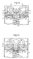
- FIG. 3 a stacking mechanism according to the second embodiment of the invention is shown.
- the second embodiment which are similar to features already discussed with reference to the first embodiment, are referenced using the same numerals and are not discussed further in detail.
- the second embodiment does not utilise a pusher plate or piston in the stacking process but incorporates two rotors with the circular profile shown in Figure 2b and as described with reference to the first embodiment.
- the banknote 1 is transported to the stacking mechanism by a banknote transport system similar to that described with reference to the first embodiment.
- the banknote 1 is transported in the region of the stacking mechanism by drive rollers 30 situated above the banknote transport plane and at either side of the cashbox aperture 4.
- Each drive roller 30 is opposed by a trapped bearing 32 situated beneath the banknote transportation plane.
- the drive rollers 30 are supported rigidly on axles 31 and the trapped bearings 32 are mounted along opposing edges 26 of the cashbox aperture 4, such that they have two rotational degrees of freedom.
- the trapped bearings 32 may be manufactured from metal or plastics material and are mounted proud of the profile of the upper surface of the cashbox 5.
- the drive rollers 30 are manufactured from plastics or any other suitable material and have a rubberised tyre or circumferential surface to positively grip the banknote 1.
- the spacing between the drive rollers 30 and the trapped bearings 32 on either side of the aperture 4 is such that even the minimum width of banknote for which the mechanism is designed may be securely held and transported.
- the maximum banknote width is approximately 95 mm.
- the minimum banknote width is approximately 70mm. In this instance this is limited by the spacing of abutment surfaces 15 and 16. In practice this spacing could be reduced to a slightly greater width than the aperture width if required. In this embodiment the aperture width is approximately 24mm.
- transportation belts may be used in the place of rollers.
- the stacking mechanism in this embodiment comprises two rotors 10, each as described with reference to the first embodiment.
- Each rotor 10 is mounted and driven in a similar manner to that described with reference to the first embodiment.
- the rotors 10 are shown to be mounted opposing each other, with sufficient clearance between them in order that they do not interfere with each other when they are rotated about their axes 11.
- a banknote 1 is shown having been transported between the drive rollers 30 and the trapped bearings 32 to a position above the cashbox aperture 4.
- the banknote 1 is shown as being transported to the stacking mechanism in a direction perpendicular to the plane of the diagram by the transportation mechanism.
- the positive gripping force exerted by the rollers 30 is removed from the banknote 1. This is achieved by raising the associated mounting axles 31 to give a clearance between the rollers 30 and the trapped bearings 32.
- FIG 3a illustrates the start of the stacking process.
- the rotors 10 are caused to rotate in synchronism about their respective axles 11 in the directions indicated by the arrows in the Figure.
- the movement of the rotors 10 is entrained using an electric motor and a gear train (not shown).
- the rotating axles 23 of the rotors 10 are brought into contact with the upper surface of the banknote 1, in a roughly central position with respect to the banknote 1.
- the synchronous operation of the rotors 10 ensures that the force exerted on banknote 1 is even. The possibility of the banknote 1 being skewed upon being stacked is therefore diminished.
- the banknote 1 is freely moveable both in the transportation stage, and subsequently downwards in the direction of the cashbox 5 during the stacking process.
- this objective may be achieved by arranging the trapped bearings 32 to be moveable with respect to the fixed drive rollers 30. Prior to the stacking process they may be lowered in order to allow the banknote 1 to be stacked freely.
- the actual degree of rotation of the rotors 10 is sufficient to make the banknote contacting portions 23 of the rotors 10 reach or just pass the point of maximum depth of penetration into the cashbox 5. This facilitates the unrolling of the banknote and reduces the risk of the banknote being incorrectly stacked.
- the banknote stack As the rotors 10 rotate in the reverse direction, out of the cashbox 5, the banknote stack is biased under the influence of the spring 14 towards the aperture 4, against the retreating rotors 10. As the rotors 10 withdraw from cashbox 5 entirely, the stack surface 12; 13 is urged by the compression spring 14 against the abutment surfaces 15, 16 situated on the inside of the upper surface of the cashbox 5. The abutment surfaces 15, 16 ensure that positive control over the stack surface 12; 13 is always maintained.
- the aperture 4 of the cashbox 5 may be smaller in this embodiment due to the absence of the pusher plate, which may increase the degree of security which may be imparted to a cashbox for use with this embodiment.
- the minimum width of the aperture 4 must be at least twice the thickness of rotor arm 20, approximately 14mm. Therefore a minimum aperture width of approximately 15 mm may be achieved in this embodiment.
- both rotors 10 act simultaneously, as opposed to the arrangement in the first embodiment where the rotor and the pusher plate are actuated at different times.
- the third embodiment of the invention operates in a similar manner to that described with reference to the second embodiment and similar features will not be described further in detail.
- the rotors 40 are of a slightly different design compared to those previously described.
- rotor 40 has no to support bar 22 or rotating axle 23.
- Rotor 40 has three rotor arms 41 (although this number could be higher or lower).
- At the end of each rotor arm 41 is a wheel 42.
- Each wheel 42 forms a banknote engaging surface, which fulfils the same function as the rotating axle 23 of rotor 10.
- the rotating wheels 42 may be replaced by non-rotating banknote contacting surface made from a low friction such as PTFE.
- aperture 4 of cashbox 5 may be made narrower, yet still allow the entry of the rotors in order to stack the banknotes; thus, cashbox 5 may be more easily made secure when it is removed from the validator.
- the minimum width of the cashbox aperture 4 (approximately 10 mm in this embodiment) is limited by the thickness of one rotor arm 41, which in this case is 7mm.
- the stacking mechanism operates in a similar manner to that described with reference to the second and third embodiments and similar features will not be described further.
- the positional control exerted over the banknote 1 during the stacking process is improved through the use of a banknote contacting membrane 50 interposed between the rotors 10; 40 and the banknote 1.
- a membrane 50 according to the present embodiment is illustrated in plan view in Figure 5.
- the membrane 50 may be made of various wear resistant materials which may be produced in thin flexible sheets and suitable for rolling on rollers; such as polyester, mylar (TM), kevlar (TM) and Gore-tex (TM).
- the membrane 50 is symmetrical about the dotted centre line and has a single connection point 51 situated at each end.
- the connection points 51 provide a means of attaching the membrane 50 to rollers 53, 54 upon which the membrane 50 is wound. It is advantageous to have a single point of attachment to each roller as this reduces the possibility of the membrane 50 becoming skewed when it is wound on or off the rollers 53, 54.
- the membrane 50 also comprises a central friction strip 52, situated on its banknote contacting side. This is beneficial in terms of increasing control over the banknote 1 during the stacking process by increasing the level of friction between the membrane 50 and the banknote 1.
- the friction strip 52 is made from vulcanised rubber which is bonded to the membrane 50. However, it may be made from any other suitable high friction material and attached to the membrane by any other suitable method, such as by stitching.
- the membrane 50 is mounted upon rollers 53, 54, as shown in Figure 6, which are spring loaded and mounted in the chassis of the stacker mechanism. This is achieved using springs (not shown) internal to the rollers 53, 54. The effect of the springs is to bias the rollers 53, 54 in the directions indicated by the arrows in Fig 6a. Therefore, in its resting state the membrane 50 is held taught between the rollers 53, 54, entrained over two guide rollers 55, 56, which are also mounted in the chassis of the stacker mechanism, as shown in Figure 6.
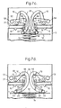
- FIG 7a illustrates the start of the stacking cycle, which is as described with reference to the second and third embodiments, with the exception of the addition of membrane 50, and so common features will not be discussed further in detail.
- the rotors 10; 40 As the rotors 10; 40 are caused to rotate about their respective axes 11 they contact the membrane 50, which is positioned between the banknote 1 and the rotors 10; 40. Further rotation of the rotors 10 causes the membrane 21 to be pushed downwards and entrained first around the guide rollers 55, 56, as shown in Figure 7a and then around trapped bearings 32, which are located at either side of the aperture 4.
- the purpose of the guide rollers 55, 56 is to prevent the membrane 50 from snagging on the rollers 30.
- the rollers 53, 54 are caused to rotate in the directions indicated by the arrows in Figure 7a, against their respective spring force bias, as the membrane 50 unrolls from them under the action of the rotors 10; 40.
- the rotors 10; 40 move the membrane 50 downwards through the banknote transportation plane, as shown in Figure 7b, the banknote 1 is contacted by the friction strip 52.
- the friction strip 52 displaces only in a vertical sense, and hence remains centred in the mechanism throughout the stacking process, it serves to reduce any skewing of the banknote which might otherwise occur.
- membrane 50 is tensioned by the springs in axles 53, 54, which ensure that there is no slack in the membrane 50 during the removal of rotors 10; 40, from cashbox 5. Since there is no relative movement between the membrane 50 and the stacked banknote 1 in the plane of the surface of the stack 12;13, the banknote 1 is not disturbed by the withdrawal of the rotors 10; 40 and the membrane 50.
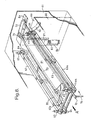
- FIG. 8 and 9 a stacking mechanism according to the fifth embodiment of the invention is shown.
- the mechanism of this embodiment fulfils the same functions as those described in the first embodiment.
- Features in this embodiment which are similar to features already discussed are referenced using the same reference numerals and will not be discussed further in detail.
- the mechanism of the first embodiment incorporates a stacking mechanism and a transportation mechanism which are housed in a banknote handling apparatus, to which a cashbox is removably attached
- the mechanism of the current embodiment incorporates part of the transportation mechanism and the entire stacking mechanism in the cashbox itself.
- This feature greatly enhances the level of security which may be provided for a detachable cashbox.
- the aperture 4 through which banknotes are stacked is internal to the outer casing of the cashbox. Therefore, on being detached from the banknote handling device, for example a validator, there is no external aperture large enough to allow a person to tamper with the contents of the cashbox.
- the cashbox according to the present embodiment consists of an inner and an outer envelope, referenced by numerals 60 and 61 respectively.
- a banknote 1 is introduced into the cashbox 5 in the direction of arrow "A", by the transportation mechanism of a banknote handling apparatus to which the cashbox 5 is attached.
- the aperture (not shown) through which a banknote 1 may be introduced into the cashbox need only be slightly larger than the width-wise cross sectional dimensions of the largest banknote 1 with which the apparatus is designed to work, further increasing the level of security of the cashbox 5.
- the banknote 1 is engaged by opposing pairs of belts 62, 62a and 63, 63a which are arranged to grip the banknote 1 along each of its longitudinal edges.
- the belts 62, 62a and 63, 63a are driven by rollers 64, which in turn are driven by a connection (not shown) from the banknote handling apparatus drive mechanism through an aperture (not shown) in the wall of cashbox 5.
- the upper belts 62, 63 of the drive arrangement are biased using springs 65 in order to keep the banknote 1 firmly in contact with opposing belts 62a, 63a.
- banknotes are stacked onto a plate 13 which is supported by a spring 14.
- This allows the banknote stack 12 to be displaced by the stacking mechanism as a new banknote 1 is stacked and to return as the stacking mechanism retreats in order that the uppermost banknote 1 in the stack 12 abuts the abutment surfaces 15, 16 of the upper wall 66 of the inner envelope 60 of the cashbox 5.
- the banknote stack 12 is always maintained under positive control as discussed in previous embodiments.
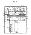
- the stacking mechanism comprises an actuation lever 70 which is moveable in the direction of the arrow shown in Figure 8 by an external drive mechanism (not shown).
- This may take the form of a simple gear, for example, connected via an aperture in the cashbox wall to an electric motor housed in the banknote handling apparatus.
- the rotation of actuation lever 70 causes the rigidly connected assembly of rod 71, connecting arm 72 and roller axle 73 to rotate about the longitudinal axis of rod 71, such that the roller axle 73 enters the cashbox aperture 4 (best seen in Figure 9) in a radial channel 90 in the end wall of the inner cashbox envelope 60.
- the actuation lever 70, rod 71, connecting arm 72 and roller axle 73 may be manufactured from any suitable rigid material such as steel and interconnected using standard manufacturing techniques.
- the roller axle 73 has mounted at either end a roller 74, 75. Each roller 74, 75 is provided with a rubber tyre for engaging a piston 80, 81, 84 which will be described in more detail below.
- the roller axle 73 is secured at the end of roller 74 only, to connecting arm 72; thus avoiding the need for providing further channels in the internal envelope 60, which would be required for securing the second end of roller axle 73.
- the roller axle 73 is free to rotate against the spring bias of an internally mounted spring (not shown) housed in connecting arm 72, the biasing of which acts in the direction of the arrow shown in Figure 9.
- the rollers 74 and 75 are mounted on the roller axle 73 such that they are free to rotate independently of the roller axle 73.
- the banknote stacking mechanism further comprises a piston assembly, as mentioned above.
- the piston assembly comprises a banknote engaging plate 80.
- the plate 80 is dimensioned such that it just fits through the aperture 4 of the upper surface of the inner envelope 60 of cashbox 5, as viewed in Figures 8 and 9.
- the aperture 4 is in turn dimensioned such that its length (in the direction of banknote transportation) exceeds the length of the longest banknote with which the apparatus is designed to function.
- the piston assembly is mounted in a slot 86 in the end wall of the inner envelope 60 which receives a reduced width portion of a guide piece 81 of the piston body, such that the guide piece 81 is free to move linearly in the slot 86.
- the guide piece 81 is held in a planar relationship with the end wall of the inner envelope 60 by the end wall of the outer envelope, with which it is a sliding fit.
- the guide piece 81 is acted on by a spring 83 which biases the piston body towards the upper surface 66 of the inner envelope 60 of cashbox 5 as viewed in Figures 8 and 9, such that in its resting condition, as is shown in Figure 9, the plate 80 of the piston body is situated above the plane of a banknote 1 which is held between each side of the transport mechanism.
- the piston body also comprises an arm 84 which extends perpendicularly to the guide piece 81 and which is co-planar with the plate 80.
- the entire piston body assembly may be made from any suitable rigid material, such as steel or a plastics material and may be made as a one piece moulding or may be assembled, using standard manufacturing techniques from components parts.
- a membrane 91 Entrained about the roller axle 73 is a membrane 91, similar to that described in the fourth embodiment. One edge of the membrane 91 is secured to the roller axle 73. The membrane 91 extends from near the roller 75, along approximately the entire length of the plate 80.
- the other edge of the membrane 91 is secured to a longitudinal edge of plate 80, for example by adhesion, as is shown in Figures 8 and 9.
- the banknote 1 is transported by the transportation mechanism and held stationary above the aperture 4 prior to the initiation of the stacking procedure. Subsequently, the belt transport system 62 is raised relative to its opposing belt 62a in order to create a clearance between the belts 62 and 62a such that an edge of the banknote 1 may be withdrawn during the stacking operation. This is initiated by the rotation of actuation lever 70 in the direction indicated by the arrow on Figure 9 and as previously described this results in the rotation of roller axle 73 into the inner envelope 60 of cashbox 5 along the radial slot 90 in the end wall of the inner cashbox 60.
- roller 74 acts on the arm 84 of the piston body, forcing the piston body to slide vertically down into the inner envelope 60 of cashbox 5, along slot 86.
- This causes the underside of the plate 80 to come into contact with the upper surface of the banknote 1, which is entrained by the plate 80 through the aperture 4 and onto the upper surface of the stack of banknotes 12 in the cashbox, or, onto the support plate 13 if the cashbox is empty.
- the second banknote edge is released by the raising of the belt transport system 63 relative to its opposing belt transport system 63a.
- the final stacked position of the banknote is laterally offset with regard to the position of the banknotes during transportation.
- roller 74 continues to exert a downward force on the piston body, via the extreme end of arm 84. This is despite the fact that the roller axle 73 is no longer situated above plate 80.
- the actuation mechanism then proceeds to drive actuation lever 73 in the reverse direction to rotate the roller axle 73 back out of the inner envelope 60 of cashbox 5 along the radial path defined by slot 90.
- the biasing force of spring 83 causes the piston body to return to its normal position, shown in full line in Figure 9.
- the present embodiment has the advantages described earlier with respect to the first embodiment of being tolerant of misalignment of the banknote 1 as it is presented for stacking, since no datum edge is relied upon in order to effect the stacking operation.
- each banknote 1 is effectively stacked by positioning part of the banknote 1 on the stack 12 and subsequently flattening the remainder against the stack 12, this embodiment is also able to cope with a wide range of banknote sizes.
- the presence of the membrane 91 further increases the control which may be exerted upon the banknote 1 during the stacking operation.
- the tensile stresses imparted to the banknote 1 are reduced by the presence of the membrane 50. Therefore, the chances of the banknote 1 being torn by the stacking process are further reduced. Accordingly, the speed of the stacking cycle may be further increased.
- banknote stacking apparatus may be used in various applications, particularly where banknotes are automatically accepted and validated such as in automated vending machines and banknote changing machines.
- a banknote validating machine 100 is shown in conjunction with a cashbox 5.
- Figure 10b an idealised sectional view through the machine 100 is shown. This shows a banknote 1 on the point of being inserted into an aperture 101 from where it is transported along a banknote transportation system 102 by a drive unit 103 and validated by a validation apparatus 104.
- the transportation system 102 then transports the banknote 1 to a stacking arrangement 105 so that the banknote 1 may be stacked in the cashbox 5 as has been described in previous embodiments, the stacking arrangement 105 may be located in the validator 100 as it is shown in Figure 10b or alternatively in the cashbox 5 itself.
- stacking arrangement 105 employed in a banknote accepting machine may conform to any one of the previously described embodiments.
- the present invention could be used to stack bundles of banknotes, which have been held, for example, in a temporary storage device such as an escrow.
- both the rotors and the pusher plate may be driven by a single, non-reversible electric motor, their actuation timing being controlled through the use of cams, for example.
- the banknote transport mechanism may be arranged to deliver banknotes for stacking at predetermined intervals, allowing the continuous operation of the stacking mechanism.
- the inventive concept of the present invention may be realised using stacking members which would not normally be termed rotors.
- the opposing rotors of the second embodiment may be replaced with parallel rods, each supported at either end in an "L" shaped channel. By moving the rods in the "L" shaped channels the required downward and sideways movement for stacking a sheet according to the present invention may be accomplished.
Landscapes
- Engineering & Computer Science (AREA)
- Mechanical Engineering (AREA)
- Physics & Mathematics (AREA)
- General Physics & Mathematics (AREA)
- Pile Receivers (AREA)
- Sheets, Magazines, And Separation Thereof (AREA)
Abstract
Description
Claims (31)
- A device for stacking banknotes (1), comprising a cashbox (5) and a stacker (9, 10, 20, 41) arranged to stack banknotes of predetermined dimensions in said cashbox, said cashbox having a surface including an aperture (4) therein, said device being arranged to receive a banknote at a position overlying said aperture, and said stacker being arranged to push said banknote through said aperture such that when said banknote reaches a maximum depth in said cashbox relative to said aperture, a portion of said banknote extends outside said cashbox through said aperture, the stacker further being arranged so the banknote is moved into a stacked position by moving the banknote along the stack only in one direction.
- A device according to claim 1, further comprising a first pushing means for pushing the banknote vertically towards the stack.
- A device according to claim 2, further comprising a second pushing means for pushing the banknote along the stack.
- A device according to any preceding claim wherein the stacker is external to the cashbox.
- A device according to any preceding claim wherein the stacker is internal and incorporated within the cashbox.
- A device according to any preceding claim further comprising an extensible membrane positioned between the stacker and the banknote, the extensible membrane arranged to contact the banknote during the stacking procedure.
- A device for stacking banknotes (1), comprising a cashbox (5) and a stacker (9, 10, 20, 41) arranged to stack banknotes of predetermined dimensions in said cashbox, said cashbox having a surface including an aperture (4) therein, said aperture having a dimension in a first direction of W, said device being arranged to receive a banknote at a position overlying said aperture, said banknote having a dimension in said first direction of L, said stacking means being arranged to push said banknote through said aperture and into a stacked position in said cashbox, wherein said banknote is pushed to a predetermined maximum depth D in said cashbox relative to said aperture such that D < (L- W)/2.
- A device according to claim 7, wherein the stacker comprises at least one rotor (10, 20, 41) arranged to rotate about an axis (11), such that it may pass through the aperture and move along a stack surface (12; 13).
- A device according to claim 8, wherein the stacker comprises a piston (9) arranged to push a banknote through the aperture such that the banknote contacts the stack surface.
- A device according to claim 8, wherein the stacker further comprises a second rotor (20, 41), each said rotor being supported on an axle (11) and comprising a banknote engaging portion (23, 42) free to rotate about a respective axle, the banknote engaging portion of each rotor being arranged to pass through said aperture and to contact the stack (12).
- A device according to claim 10, wherein the stacker is arranged to move along the surface of the stack simultaneously in two mutually opposed directions, each said direction being substantially perpendicular to the length of the aperture.
- A device according to any one of claims 10 and 11, wherein said rotor has at least one roller (23, 42) located on the banknote engaging portion, free to rotate on the surface of the banknote.
- A device according any one of claims 10, 11 and 12, wherein the banknote engaging portion is formed of a low friction substance.
- A device according to claim 13, wherein the banknote engaging portion of each rotor comprises PTFE.
- A device according to any of claims 7 to 14 further comprising an extensible membrane (50) positioned between the stacker and the banknote, arranged to contact the banknote during the stacking procedure.
- A device according to claim 15, wherein the membrane is mounted on at least one spring biased roller (53, 54; 74).
- A device according to claim 15 or claim 16, wherein the membrane comprises a frictionfull banknote contacting portion (52).
- A device according to any of claims 7 to 17, wherein the aperture comprises at least one roller (32) around which the banknote is entrained whilst the banknote is being pushed through said aperture.
- A device according to any of claims 7 to 18, wherein the device further comprises means (14) to bias the stack toward the aperture.
- A device according to claim 19, wherein the biasing means comprises at least one spring.
- A device according to any of claims 7 to 20, further comprising means (15, 16) to retain the stacked banknote in a stack.
- A device according to any of claims 7 to 21, wherein the width of the aperture is less than the minimum width of a banknote to be stacked.
- A device according to any of claims 7 to 22, wherein the width of the aperture is approximately half of the width of a banknote.
- A device according to any of claims 7 to 23, wherein the width of the aperture is approximately a quarter of the width of a banknote or less.
- A device according to any of claims 7 to 24, wherein the width of the aperture is approximately 24 mm.
- A device according to any of claims 7 to 25, wherein the width of the aperture is approximately 10 mm or more.
- A device according to any of claims 7 to 26, wherein the width of the aperture is approximately 15 mm or more.
- A device for stacking banknotes, comprising a cashbox and a stacker arranged to stack banknotes of predetermined dimensions in said cashbox, said cashbox having a surface including an aperture therein, said device being arranged to receive a banknote at a position overlying said aperture, and said stacker being arranged to push said banknote through said aperture such that when said banknote reaches a maximum depth in said cashbox relative to said aperture, a portion of said banknote extends outside said cashbox through said aperture.
- A device for stacking documents comprising a stacker and a stack surface, the stacker being arranged to push a document partially through an aperture defined by at least one surface such that the document partially contacts the stack, the stacker being further arranged to move along the stack, entraining the document through said aperture into a stacked position, wherein the stacker comprises an extensible membrane positioned between the stacker and the document, arranged to contact the banknote during the stacking procedure.
- A device for stacking documents comprising: a document stacking means and a stack; the document stacking means being arranged to push a document partially through an aperture defined by at least one surface such that the document at least partially contacts the stack, the document stacking means being further arranged to move along the stack and under the surface, entraining the document through said aperture into a stacked position.
- A device for encashing banknotes, comprising an encashing means and a cashbox, the cashbox comprising an aperture in a surface, the encashing means being arranged to push a banknote partially through said aperture from a first side to a second side of the surface, in a direction substantially perpendicular to the plane of said surface and then to entrain the banknote through the aperture by moving on the second side of the plane in a direction substantially parallel to the plane of the surface.
Applications Claiming Priority (3)
| Application Number | Priority Date | Filing Date | Title |
|---|---|---|---|
| GB9813559 | 1998-06-23 | ||
| GB9813559A GB2338704B (en) | 1998-06-23 | 1998-06-23 | Banknote stacking apparatus |
| EP99304879A EP0967165B1 (en) | 1998-06-23 | 1999-06-22 | Banknote stacking apparatus |
Related Parent Applications (1)
| Application Number | Title | Priority Date | Filing Date |
|---|---|---|---|
| EP99304879A Division EP0967165B1 (en) | 1998-06-23 | 1999-06-22 | Banknote stacking apparatus |
Publications (3)
| Publication Number | Publication Date |
|---|---|
| EP1302425A2 true EP1302425A2 (en) | 2003-04-16 |
| EP1302425A3 EP1302425A3 (en) | 2003-04-23 |
| EP1302425B1 EP1302425B1 (en) | 2005-05-25 |
Family
ID=10834249
Family Applications (2)
| Application Number | Title | Priority Date | Filing Date |
|---|---|---|---|
| EP02079953A Expired - Lifetime EP1302425B1 (en) | 1998-06-23 | 1999-06-22 | Banknote stacking apparatus |
| EP99304879A Expired - Lifetime EP0967165B1 (en) | 1998-06-23 | 1999-06-22 | Banknote stacking apparatus |
Family Applications After (1)
| Application Number | Title | Priority Date | Filing Date |
|---|---|---|---|
| EP99304879A Expired - Lifetime EP0967165B1 (en) | 1998-06-23 | 1999-06-22 | Banknote stacking apparatus |
Country Status (5)
| Country | Link |
|---|---|
| US (1) | US6244589B1 (en) |
| EP (2) | EP1302425B1 (en) |
| DE (2) | DE69925517T2 (en) |
| ES (2) | ES2240652T3 (en) |
| GB (1) | GB2338704B (en) |
Cited By (2)
| Publication number | Priority date | Publication date | Assignee | Title |
|---|---|---|---|---|
| EP2043059A3 (en) * | 2007-09-28 | 2009-11-18 | Hitachi-Omron Terminal Solutions, Corp. | Paper sheet storing apparatus, paper sheet handling system, and automatic teller machine |
| EP2195792A4 (en) * | 2007-08-30 | 2010-09-08 | Crane Canada Co | Energy-efficient compact device for dispensing and accumulating bank notes |
Families Citing this family (31)
| Publication number | Priority date | Publication date | Assignee | Title |
|---|---|---|---|---|
| JP3779076B2 (en) * | 1998-10-06 | 2006-05-24 | 株式会社日本コンラックス | Banknote handling equipment |
| US6712352B2 (en) * | 2000-10-17 | 2004-03-30 | Mars Incorporated | Lockable removable cassette |
| DE10105242C1 (en) * | 2001-02-06 | 2002-07-25 | Wincor Nixdorf Gmbh & Co Kg | Sheet stacking device e.g. for banknotes or cheques, has two spaced rollers reciprocated parallel to sheet stack support surface with guide surfaces for sheet deposition positioned between them |
| EP1244075A1 (en) * | 2001-03-21 | 2002-09-25 | Mars Incorporated | Banknote store |
| TW540014B (en) * | 2001-04-27 | 2003-07-01 | Asahi Seiko Co Ltd | An automatic bill storage device |
| JP3932311B2 (en) * | 2001-10-16 | 2007-06-20 | 旭精工株式会社 | Automatic bill pressing device for bill storage device |
| US6607189B2 (en) * | 2001-12-12 | 2003-08-19 | Mars Incorporated | Document recycle and payout device |
| EP1323655A1 (en) * | 2001-12-28 | 2003-07-02 | Mars Incorporated | Sheet stacking apparatus comprising a pusher with extendible lateral portions |
| EP1323656B1 (en) * | 2001-12-28 | 2007-04-11 | MEI, Inc. | Sheet stacking apparatus comprising a pusher with at least one lateral extendible portion |
| JP4223735B2 (en) * | 2002-05-15 | 2009-02-12 | 株式会社日本コンラックス | Banknote handling equipment |
| JP2004359400A (en) | 2003-06-04 | 2004-12-24 | Nippon Conlux Co Ltd | Loading and storing device for paper sheet |
| JP2005206353A (en) * | 2004-01-26 | 2005-08-04 | Asahi Seiko Kk | Bill movement device in bill storage device |
| TWI274716B (en) * | 2004-06-24 | 2007-03-01 | Int Games System Co Ltd | Sheet cartridge |
| GB0600322D0 (en) * | 2006-01-09 | 2006-02-15 | Rue De Int Ltd | Stacking cassette |
| CA2539866A1 (en) * | 2006-03-16 | 2007-09-16 | Crane Canada Co. | Flat banknote dispenser |
| DE102006060619A1 (en) * | 2006-12-21 | 2008-06-26 | Adp Gauselmann Gmbh | Device for receiving and issuing paper currency |
| GB0803671D0 (en) | 2008-02-28 | 2008-04-09 | Intelligent Deposit Systems Lt | Document handling |
| DE102009003994A1 (en) | 2009-01-07 | 2010-07-08 | Giesecke & Devrient Gmbh | Container for holding documents of value and method and device for accepting and storing documents of value |
| DE102011117013A1 (en) | 2011-10-26 | 2013-05-02 | Giesecke & Devrient Gmbh | Single-piston device for containment vessel used in banknote processing machine, has separating elements which are moved relative to driven out movement of stamper element such that entrance of tray region is enlarged or released |
| CN103021100B (en) * | 2012-11-19 | 2015-08-26 | 易程(苏州)电子科技股份有限公司 | Cash box spring weighs force mechanisms |
| JP5887318B2 (en) * | 2013-09-13 | 2016-03-16 | 日本金銭機械株式会社 | Stacker for storing paper sheets |
| CN104123784B (en) * | 2013-10-24 | 2017-05-03 | 深圳博众智能科技有限公司 | Money-pressing device |
| US10357859B1 (en) | 2014-03-06 | 2019-07-23 | Daniel J Reed | Clamping system for securing a work piece to a fixture |
| JP2018070270A (en) * | 2015-02-26 | 2018-05-10 | グローリー株式会社 | Paper sheet storage mechanism, paper sheet processing machine, and paper sheet storage method |
| JP6600827B2 (en) * | 2015-05-11 | 2019-11-06 | Necマグナスコミュニケーションズ株式会社 | Banknote storage |
| CN106023420B (en) * | 2016-05-18 | 2018-08-17 | 新达通科技股份有限公司 | A kind of bank note transport establishment used in the bank note stacking apparatus of cash recycling system |
| JP6859745B2 (en) * | 2017-02-23 | 2021-04-14 | 富士ゼロックス株式会社 | Post-processing equipment and image forming equipment |
| TWI642033B (en) * | 2017-07-19 | 2018-11-21 | 鴻發國際科技股份有限公司 | Paper storage equipment |
| WO2019118776A1 (en) * | 2017-12-13 | 2019-06-20 | Crane Payment Innovations, Inc. | Rigid chain stacker |
| CN108147167B (en) * | 2018-01-29 | 2024-01-16 | 湖北平安电工材料有限公司 | Device for separating stacked glass fiber fabrics singly |
| JP2021092865A (en) * | 2019-12-06 | 2021-06-17 | グローリー株式会社 | Paper sheet processing device and paper sheet processing method |
Family Cites Families (35)
| Publication number | Priority date | Publication date | Assignee | Title |
|---|---|---|---|---|
| US4000892A (en) | 1974-01-22 | 1977-01-04 | Ardac, Inc. | Note storage apparatus |
| US4050562A (en) | 1974-04-22 | 1977-09-27 | Mars, Inc. | Banknote escrow and stacker apparatus and method |
| JPS50146588U (en) * | 1974-05-21 | 1975-12-04 | ||
| JPS5332097A (en) | 1976-09-06 | 1978-03-25 | Fuji Electric Co Ltd | Bill kind carrying mechanism in its piling apparatus |
| DE2847774A1 (en) * | 1978-11-03 | 1980-05-14 | Agfa Gevaert Ag | DEVICE FOR COLLECTING FLEXIBLE STRIPS, IN PARTICULAR FILM STRIPS |
| JPS5781049A (en) | 1980-11-07 | 1982-05-20 | Fuji Electric Co Ltd | Apparatus for receiving sheets of paper |
| US4418824A (en) | 1981-07-08 | 1983-12-06 | Ardac, Inc. | Dual stacker for slot acceptor |
| JPS58207194A (en) | 1982-05-28 | 1983-12-02 | 株式会社日本コインコ | Paper money receiver |
| JPS5964469A (en) * | 1982-09-30 | 1984-04-12 | Fujitsu Ltd | Paper sheets containing mechanism |
| US4784274A (en) | 1983-10-03 | 1988-11-15 | Kabushiki Kaisha Nippon Coinco | Bill device |
| JPS6155037A (en) | 1984-08-22 | 1986-03-19 | Hitachi Ltd | Paper containing device |
| US4765607A (en) * | 1985-03-08 | 1988-08-23 | Mars, Incorporated | Stacker apparatus |
| JPS62159296A (en) | 1986-01-07 | 1987-07-15 | アイエム電子株式会社 | Paper money identifier/stacker |
| JPH0742028B2 (en) | 1986-03-17 | 1995-05-10 | 株式会社日本コンラックス | Banknote storage device |
| JPS62290670A (en) * | 1986-06-09 | 1987-12-17 | Toshiba Corp | Stacking device for paper sheets |
| US4732375A (en) * | 1986-07-24 | 1988-03-22 | Cubic Western Data | Apparatus for handling strip-like media |
| US4844446A (en) | 1986-12-03 | 1989-07-04 | Standard Change-Makers, Inc. | Multiple-compartment currency stacker-sorter |
| JPH01295391A (en) | 1987-06-24 | 1989-11-29 | I M Denshi Kk | Identifying device for printed matter |
| JPH01308352A (en) * | 1987-06-24 | 1989-12-13 | I M Denshi Kk | Bill stacking device |
| US4834230A (en) | 1987-11-06 | 1989-05-30 | I.M. Electronics Co, Ltd. | Apparatus for discriminating paper money and stacking the same |
| GB2219990B (en) | 1988-06-22 | 1992-07-29 | Xerox Corp | Sheet stacking and inverting apparatus |
| US5076413A (en) * | 1990-07-13 | 1991-12-31 | General Signal Corporation | Multiple bill escrow and storage apparatus |
| DE59108910D1 (en) | 1990-08-06 | 1998-02-05 | Mars Inc | Device for stacking sheets |
| JP2941502B2 (en) | 1991-07-31 | 1999-08-25 | 株式会社東芝 | Paper sheet stacking device |
| US5322275A (en) | 1991-10-04 | 1994-06-21 | Coin Bill Validator Inc. | Bill accumulating and stacking device |
| JPH06150106A (en) | 1992-11-05 | 1994-05-31 | Nippon Conlux Co Ltd | Paper money identifying device |
| JP3118099B2 (en) | 1992-12-03 | 2000-12-18 | 株式会社日本コンラックス | Banknote handling equipment |
| US5344135A (en) | 1992-12-21 | 1994-09-06 | Japan Cash Machine Co., Ltd. | Currency stacker resistible against unauthorized extraction of currency therefrom |
| EP0684929B1 (en) | 1993-02-16 | 2000-05-03 | Mars Incorporated | Device for stacking sheets |
| US5388817A (en) | 1993-10-06 | 1995-02-14 | Gameax Corporation | Note stacker mechanism |
| JP2932338B2 (en) | 1993-11-05 | 1999-08-09 | 株式会社日本コンラックス | Banknote handling equipment |
| US5624017A (en) | 1994-04-06 | 1997-04-29 | Gap Technologies, Inc. | Multi-purpose currency validator with compact low power cassette stacker |
| US5803227A (en) | 1995-06-06 | 1998-09-08 | International Game Technology | Bill stacker |
| IT1277765B1 (en) | 1995-06-26 | 1997-11-12 | Mec L A R Di Lonati Lorenzo & | BANKNOTE STACKING AND COLLECTING DEVICE WITH THE POSSIBILITY OF RETURN OF THE SAME |
| US5662202A (en) | 1995-11-24 | 1997-09-02 | Ardac Incorporated | Currency validator with cassette cash box |
-
1998
- 1998-06-23 GB GB9813559A patent/GB2338704B/en not_active Expired - Fee Related
-
1999
- 1999-06-22 DE DE69925517T patent/DE69925517T2/en not_active Expired - Lifetime
- 1999-06-22 DE DE69904116T patent/DE69904116T2/en not_active Expired - Lifetime
- 1999-06-22 ES ES02079953T patent/ES2240652T3/en not_active Expired - Lifetime
- 1999-06-22 US US09/338,481 patent/US6244589B1/en not_active Expired - Lifetime
- 1999-06-22 EP EP02079953A patent/EP1302425B1/en not_active Expired - Lifetime
- 1999-06-22 EP EP99304879A patent/EP0967165B1/en not_active Expired - Lifetime
- 1999-06-22 ES ES99304879T patent/ES2187120T3/en not_active Expired - Lifetime
Cited By (2)
| Publication number | Priority date | Publication date | Assignee | Title |
|---|---|---|---|---|
| EP2195792A4 (en) * | 2007-08-30 | 2010-09-08 | Crane Canada Co | Energy-efficient compact device for dispensing and accumulating bank notes |
| EP2043059A3 (en) * | 2007-09-28 | 2009-11-18 | Hitachi-Omron Terminal Solutions, Corp. | Paper sheet storing apparatus, paper sheet handling system, and automatic teller machine |
Also Published As
| Publication number | Publication date |
|---|---|
| EP0967165A3 (en) | 2000-04-26 |
| ES2240652T3 (en) | 2005-10-16 |
| GB2338704A (en) | 1999-12-29 |
| DE69904116T2 (en) | 2003-09-11 |
| ES2187120T3 (en) | 2003-05-16 |
| EP0967165A2 (en) | 1999-12-29 |
| DE69925517D1 (en) | 2005-06-30 |
| EP1302425B1 (en) | 2005-05-25 |
| EP0967165B1 (en) | 2002-11-27 |
| GB2338704B (en) | 2002-12-31 |
| DE69904116D1 (en) | 2003-01-09 |
| EP1302425A3 (en) | 2003-04-23 |
| GB9813559D0 (en) | 1998-08-19 |
| US6244589B1 (en) | 2001-06-12 |
| DE69925517T2 (en) | 2006-01-26 |
Similar Documents
| Publication | Publication Date | Title |
|---|---|---|
| EP0967165B1 (en) | Banknote stacking apparatus | |
| US9517904B2 (en) | Device for handling single sheets, for introducing and distributing rectangular single sheets, especially bank notes, respectively into and out of a container | |
| EP1319619A2 (en) | Device for stacking sheets | |
| US8262076B2 (en) | Media depository | |
| US6971645B2 (en) | Device for selecting mail items | |
| EP0611718A1 (en) | Sheet stacking apparatus | |
| TW202342355A (en) | Friction handling device and paper handling device | |
| EP0542226B1 (en) | Paper separating/driving apparatus and its controlling method and automatic teller operating thereon | |
| TW202341085A (en) | Conveying guide driving mechanism, paper conveying device, control method of paper conveying device, and paper processing device | |
| US6540225B2 (en) | Storing device for paper sheets | |
| JP6855329B2 (en) | Paper leaf matching transport device | |
| JP3824815B2 (en) | Banknote storage mechanism in banknote deposit machine | |
| JPH0644928Y2 (en) | Banknote storage device | |
| US20260008644A1 (en) | A banknote stack transport arrangement and a cash handling machine | |
| JP2013058072A (en) | Bill return device | |
| JPH0558474A (en) | Paper sheet housing box | |
| JP3927290B2 (en) | Paper sheet storage device | |
| JP4561316B2 (en) | Banknote handling equipment | |
| JPH05301646A (en) | Paper sheet separation device | |
| JP2810117B2 (en) | Paper sheet separation device | |
| JP2013206344A (en) | Paper money recirculation device | |
| JP5261815B2 (en) | Banknote handling apparatus and banknote handling apparatus | |
| JPH0448715B2 (en) | ||
| JPS62121147A (en) | Paper sheet processing equipment | |
| JPS62146837A (en) | Paper handling equipment |
Legal Events
| Date | Code | Title | Description |
|---|---|---|---|
| PUAI | Public reference made under article 153(3) epc to a published international application that has entered the european phase |
Free format text: ORIGINAL CODE: 0009012 |
|
| PUAL | Search report despatched |
Free format text: ORIGINAL CODE: 0009013 |
|
| AC | Divisional application: reference to earlier application |
Ref document number: 0967165 Country of ref document: EP Kind code of ref document: P |
|
| AK | Designated contracting states |
Designated state(s): CH DE ES FR GB IT LI |
|
| AK | Designated contracting states |
Designated state(s): CH DE ES FR GB IT LI |
|
| 17P | Request for examination filed |
Effective date: 20031014 |
|
| AKX | Designation fees paid |
Designated state(s): DE ES GB IT |
|
| 17Q | First examination report despatched |
Effective date: 20040105 |
|
| GRAP | Despatch of communication of intention to grant a patent |
Free format text: ORIGINAL CODE: EPIDOSNIGR1 |
|
| GRAS | Grant fee paid |
Free format text: ORIGINAL CODE: EPIDOSNIGR3 |
|
| GRAA | (expected) grant |
Free format text: ORIGINAL CODE: 0009210 |
|
| AC | Divisional application: reference to earlier application |
Ref document number: 0967165 Country of ref document: EP Kind code of ref document: P |
|
| AK | Designated contracting states |
Kind code of ref document: B1 Designated state(s): DE ES GB IT |
|
| REG | Reference to a national code |
Ref country code: GB Ref legal event code: FG4D |
|
| REF | Corresponds to: |
Ref document number: 69925517 Country of ref document: DE Date of ref document: 20050630 Kind code of ref document: P |
|
| REG | Reference to a national code |
Ref country code: ES Ref legal event code: FG2A Ref document number: 2240652 Country of ref document: ES Kind code of ref document: T3 |
|
| PLBE | No opposition filed within time limit |
Free format text: ORIGINAL CODE: 0009261 |
|
| STAA | Information on the status of an ep patent application or granted ep patent |
Free format text: STATUS: NO OPPOSITION FILED WITHIN TIME LIMIT |
|
| 26N | No opposition filed |
Effective date: 20060228 |
|
| REG | Reference to a national code |
Ref country code: GB Ref legal event code: 732E |
|
| REG | Reference to a national code |
Ref country code: GB Ref legal event code: 732E |
|
| PGFP | Annual fee paid to national office [announced via postgrant information from national office to epo] |
Ref country code: DE Payment date: 20120620 Year of fee payment: 14 |
|
| PGFP | Annual fee paid to national office [announced via postgrant information from national office to epo] |
Ref country code: GB Payment date: 20120620 Year of fee payment: 14 |
|
| PGFP | Annual fee paid to national office [announced via postgrant information from national office to epo] |
Ref country code: IT Payment date: 20120620 Year of fee payment: 14 |
|
| PGFP | Annual fee paid to national office [announced via postgrant information from national office to epo] |
Ref country code: ES Payment date: 20120726 Year of fee payment: 14 |
|
| GBPC | Gb: european patent ceased through non-payment of renewal fee |
Effective date: 20130622 |
|
| REG | Reference to a national code |
Ref country code: DE Ref legal event code: R119 Ref document number: 69925517 Country of ref document: DE Effective date: 20140101 |
|
| PG25 | Lapsed in a contracting state [announced via postgrant information from national office to epo] |
Ref country code: DE Free format text: LAPSE BECAUSE OF NON-PAYMENT OF DUE FEES Effective date: 20140101 Ref country code: GB Free format text: LAPSE BECAUSE OF NON-PAYMENT OF DUE FEES Effective date: 20130622 |
|
| PG25 | Lapsed in a contracting state [announced via postgrant information from national office to epo] |
Ref country code: IT Free format text: LAPSE BECAUSE OF NON-PAYMENT OF DUE FEES Effective date: 20130622 |
|
| REG | Reference to a national code |
Ref country code: ES Ref legal event code: FD2A Effective date: 20140707 |
|
| PG25 | Lapsed in a contracting state [announced via postgrant information from national office to epo] |
Ref country code: ES Free format text: LAPSE BECAUSE OF NON-PAYMENT OF DUE FEES Effective date: 20130623 |