EP1302620A2 - Rouleau à ressort - Google Patents
Rouleau à ressort Download PDFInfo
- Publication number
- EP1302620A2 EP1302620A2 EP02450202A EP02450202A EP1302620A2 EP 1302620 A2 EP1302620 A2 EP 1302620A2 EP 02450202 A EP02450202 A EP 02450202A EP 02450202 A EP02450202 A EP 02450202A EP 1302620 A2 EP1302620 A2 EP 1302620A2
- Authority
- EP
- European Patent Office
- Prior art keywords
- spring
- shaft
- guide rod
- coupling
- shaft according
- Prior art date
- Legal status (The legal status is an assumption and is not a legal conclusion. Google has not performed a legal analysis and makes no representation as to the accuracy of the status listed.)
- Withdrawn
Links
- 239000004744 fabric Substances 0.000 claims abstract description 13
- 230000009471 action Effects 0.000 claims abstract description 3
- 230000008878 coupling Effects 0.000 claims abstract 8
- 238000010168 coupling process Methods 0.000 claims abstract 8
- 238000005859 coupling reaction Methods 0.000 claims abstract 8
- 241000238631 Hexapoda Species 0.000 claims description 7
- 230000002040 relaxant effect Effects 0.000 claims description 3
- 230000015572 biosynthetic process Effects 0.000 description 4
- 238000005755 formation reaction Methods 0.000 description 4
- 230000037072 sun protection Effects 0.000 description 4
- 230000008901 benefit Effects 0.000 description 3
- 230000000694 effects Effects 0.000 description 3
- 229910000831 Steel Inorganic materials 0.000 description 2
- 238000009434 installation Methods 0.000 description 2
- 239000010959 steel Substances 0.000 description 2
- XAGFODPZIPBFFR-UHFFFAOYSA-N aluminium Chemical compound [Al] XAGFODPZIPBFFR-UHFFFAOYSA-N 0.000 description 1
- 229910052782 aluminium Inorganic materials 0.000 description 1
- 230000000903 blocking effect Effects 0.000 description 1
- 230000005484 gravity Effects 0.000 description 1
- 230000010354 integration Effects 0.000 description 1
- 238000012423 maintenance Methods 0.000 description 1
- 230000007246 mechanism Effects 0.000 description 1
- 230000009467 reduction Effects 0.000 description 1
- 230000008439 repair process Effects 0.000 description 1
- 238000004804 winding Methods 0.000 description 1
Images


Classifications
-
- E—FIXED CONSTRUCTIONS
- E06—DOORS, WINDOWS, SHUTTERS, OR ROLLER BLINDS IN GENERAL; LADDERS
- E06B—FIXED OR MOVABLE CLOSURES FOR OPENINGS IN BUILDINGS, VEHICLES, FENCES OR LIKE ENCLOSURES IN GENERAL, e.g. DOORS, WINDOWS, BLINDS, GATES
- E06B9/00—Screening or protective devices for wall or similar openings, with or without operating or securing mechanisms; Closures of similar construction
- E06B9/56—Operating, guiding or securing devices or arrangements for roll-type closures; Spring drums; Tape drums; Counterweighting arrangements therefor
- E06B9/60—Spring drums operated only by closure members
-
- E—FIXED CONSTRUCTIONS
- E06—DOORS, WINDOWS, SHUTTERS, OR ROLLER BLINDS IN GENERAL; LADDERS
- E06B—FIXED OR MOVABLE CLOSURES FOR OPENINGS IN BUILDINGS, VEHICLES, FENCES OR LIKE ENCLOSURES IN GENERAL, e.g. DOORS, WINDOWS, BLINDS, GATES
- E06B9/00—Screening or protective devices for wall or similar openings, with or without operating or securing mechanisms; Closures of similar construction
- E06B9/24—Screens or other constructions affording protection against light, especially against sunshine; Similar screens for privacy or appearance; Slat blinds
- E06B9/40—Roller blinds
- E06B9/42—Parts or details of roller blinds, e.g. suspension devices, blind boxes
Definitions
- the invention relates to a spring shaft with the features of the introductory Part of claim 1.
- Known spring shafts such as those used for roller blinds (roller blinds) have a locking mechanism, which allows the roller blind in any height by a counter pressure.
- the Back pressure releases the lock, which is arranged inside the shaft bearing is out.
- Such locks are usually designed so that a Blocking part, e.g. a ball, under the action of gravity a recess falls and blocks the rotation of the shaft.
- a disadvantage of the known spring shafts is that when removing the spring shaft increased attention and adherence to the right ones Location is required to ensure that the lock is activated and remains. If this is not observed, the Danger that the spring suddenly when removing the spring shaft relaxed and the spring or other parts of the spring shaft damaged become. There is also a risk that the person holding the spring shaft expands, gets hurt. Even when installing the known Spring shafts must be paid attention to a certain position, what for Spring shafts are often attached to brands that fit into one another must be brought into alignment to ensure that the Lock is activated and remains activated.
- the invention is based, in particular for the task Use of sun protection curtains or insect screens to provide certain spring shafts, which are so designed is that with the spring shaft removed, even if on a certain Orientation and rotational position of the spring shaft is not taken into account, a complete relaxation of the spring is excluded.
- the relaxation of the spring when removing prevents a locking device under the effect of the axial tensile force of the spring of the spring shaft activated is, so that after a short rotation, for example about one Quarter turn or half turn another twist and thus preventing the spring of the spring shaft from completely relaxing is.
- This ensures that the is in a stationary mounted bearing taken part of the spring shaft when removing the spring shaft does not turn uncontrollably and the person who the Spring shaft installed or removed, can injure.
- Another advantage of the locking system according to the invention, which is built into the spring shaft, is that it works in any position, so that the spring shaft according to the invention can be used not only for vertical, but also for horizontal or inclined, rollable flat structures.
- Another advantage over known spring shafts can be that the diameter of the shaft on which the flat structure is wound can be chosen to be smaller, which, for example, requires less space for installation and / or allows a reduction in the size of the roller blind box.
- the invention is particularly for sun protection curtains and insect screens thought because with this any intermediate positions are usually not necessary as sun protection curtains or insect screens either fully open or fully are closed.
- the spring shaft according to the invention has a fabric shaft 1, e.g. out Aluminum, which is designed as a tube.
- a fabric shaft 1 e.g. out Aluminum
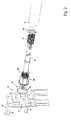
- One end of the spring shaft is via a bearing part 2 inserted into the fabric shaft 1 and one Bearing pin 3 in a bearing 4, for example with the help of Screws 5 on a roller blind box or if such is not provided is on a window or door frame or on the edge of the Opening into any component (which can also be a vehicle can) is attached, rotatably mounted (Fig. 1).
- the other end of the spring shaft (Fig. 2), namely the end of the spring shaft, in which a spring 6 is arranged is via a bearing 7, the just like the bearing 4 attached to a component with the help of screws 5 can be rotatably supported.
- the clamping part 8 has a through opening 11 (FIG. 5) in which axially parallel ribs 10 are provided.
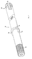
- a spring guide rod 12 (Fig. 7) with her serrated end 13 inserted so that they are opposite the clamping part 8th is not rotatable.
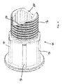
- a cylindrical extension 14 of the clamping part 8 is used Pushed spring receiving part 15, which is rotatable relative to the clamping part 8 is.
- the spring receiving part 15 carries one with an external thread provided section 16 on which the spring 6 (for example a steel coil spring), e.g. can be screwed.
- the spring receiving part 15 carries ribs extending in the axial direction 17, which engage in the fabric shaft 1 and the fabric shaft 1 rotatably connect with the spring receiving part 15.
- the spring guide rod 12 is displaceable in the axial direction the spring receiving part 15 inserted, the spring receiving part 15 is also rotatable relative to the spring guide rod 12.
- the spring guide rod 12 is on her not included in the clamping part 8 End 18 slotted so that the spring 6 with the spring guide rod 12 coupled over its end there for rotation can be by placing a bent end of the spring 6 in a slot 19 is inserted at the end of 18.
- a star 20 Fig. 8 inserted opposite the spring guide rod 12 is rotatable and the fork-shaped end 18 of the spring guide rod 12 centered in the tissue shaft 1.
- the spring receiving part 15 has in the area of its with the external thread provided, the spring 6 receiving section 16 at least one, preferably two or more, asymmetrical cutouts or recesses with inclined surfaces 25, as is particularly the case in FIGS 3 and 4 and 6 is shown.
- the cutouts with the inclined surfaces 25 can extend to the outer surface the section 16 of the spring receiving part 15 range, as shown in 3, 4 and 6 is shown, but it is also possible that the Cutouts with the inclined surfaces 25 only on the inner surface (In the area of the through hole of the spring receiving part 15) arranged are so that the threaded portion 16 of the Spring receiving part 15 is not interrupted.
- Such an embodiment of the spring receiving part 15, in which the cutouts with the Sloping surfaces 25 only within the through hole of the spring receiving part 15 are arranged, is in Fig. 6a in axial section shown.
- the spring guide rod 12 carries at a distance from it with longitudinal ribs provided, toothed and included in the clamping part 8 End 13 an annular projection 27, the formations with inclined surfaces 26 has.
- These formations with inclined surfaces 26 can as a "ratchet locking part” with those acting as a “ratchet counterpart” Cutouts interact with inclined surfaces 25 of the spring receiving part 15, around the spring receiving part 15 with respect to the spring guide rod 12 against rotation to relax the spring 6 to couple.
- the locking position shown in Fig. 4 of the invention Spring shaft is in section in Fig. 10 for the spring receiving part 15 shown in FIG. 6a. It can be seen from FIGS. 4 and 10 that by the axial train of the spring 6, the formations with the Inclined surfaces 26 on the spring guide rod 12 in the cutouts of the spring receiving part 15 engage with the inclined surfaces 25 and the clamping part 8 is pushed out of the spring receiving part 15.
- a spring shaft with a fabric shaft 1 has a spring 6, which is provided between a spring guide rod 12 and a spring guide part 15.
- Two projections with inclined surfaces 26 are provided on the spring guide rod 12 and two cutouts with inclined surfaces 25 are provided on the spring guide part 15.
Landscapes
- Engineering & Computer Science (AREA)
- Structural Engineering (AREA)
- Architecture (AREA)
- Civil Engineering (AREA)
- Operating, Guiding And Securing Of Roll- Type Closing Members (AREA)
- Springs (AREA)
- Catching Or Destruction (AREA)
Applications Claiming Priority (2)
| Application Number | Priority Date | Filing Date | Title |
|---|---|---|---|
| AT0078901U AT5643U1 (de) | 2001-10-15 | 2001-10-15 | Federwelle |
| AT200100789 | 2001-10-15 |
Publications (2)
| Publication Number | Publication Date |
|---|---|
| EP1302620A2 true EP1302620A2 (fr) | 2003-04-16 |
| EP1302620A3 EP1302620A3 (fr) | 2004-01-02 |
Family
ID=3499775
Family Applications (1)
| Application Number | Title | Priority Date | Filing Date |
|---|---|---|---|
| EP02450202A Withdrawn EP1302620A3 (fr) | 2001-10-15 | 2002-09-09 | Rouleau à ressort |
Country Status (3)
| Country | Link |
|---|---|
| EP (1) | EP1302620A3 (fr) |
| AT (1) | AT5643U1 (fr) |
| DE (1) | DE20117440U1 (fr) |
Cited By (5)
| Publication number | Priority date | Publication date | Assignee | Title |
|---|---|---|---|---|
| EP1703071A1 (fr) * | 2005-02-15 | 2006-09-20 | Hamstra B.V. | Enrouleur de store et support |
| DE102006021586B3 (de) * | 2006-05-09 | 2008-04-10 | Webasto Ag | Rolloanordnung |
| GB2481448A (en) * | 2010-06-25 | 2011-12-28 | Levolux At Ltd | Roller blind compensator apparatus |
| US11454063B2 (en) | 2020-12-14 | 2022-09-27 | Zhejiang Shengge Technology Co., Ltd. | Mounting structure for roller blind |
| EP4382704A1 (fr) * | 2022-12-06 | 2024-06-12 | Hörmann KG Brockhagen | Ensemble pour le montage de portails |
Families Citing this family (2)
| Publication number | Priority date | Publication date | Assignee | Title |
|---|---|---|---|---|
| CN1461624A (zh) * | 2002-05-29 | 2003-12-17 | 陈志明 | 用以区隔空间的可卷收遮帘 |
| DE102023120455A1 (de) * | 2023-08-01 | 2025-02-06 | Hunter Douglas Industries Switzerland Gmbh | Lager zum Lagern der Wickelwelle einer Verschattungsanlage und Verschattungsanlage mit einem solchen Lager |
Family Cites Families (1)
| Publication number | Priority date | Publication date | Assignee | Title |
|---|---|---|---|---|
| DE500236C (de) * | 1929-07-05 | 1930-06-19 | Paul Schultes | Federrolle fuer Rollvorhaenge o. dgl. mit einer Einrichtung zum Spannen und Entspannen der die Federrolle betaetigenden Feder |
-
2001
- 2001-10-15 AT AT0078901U patent/AT5643U1/de not_active IP Right Cessation
- 2001-10-24 DE DE20117440U patent/DE20117440U1/de not_active Expired - Lifetime
-
2002
- 2002-09-09 EP EP02450202A patent/EP1302620A3/fr not_active Withdrawn
Cited By (5)
| Publication number | Priority date | Publication date | Assignee | Title |
|---|---|---|---|---|
| EP1703071A1 (fr) * | 2005-02-15 | 2006-09-20 | Hamstra B.V. | Enrouleur de store et support |
| DE102006021586B3 (de) * | 2006-05-09 | 2008-04-10 | Webasto Ag | Rolloanordnung |
| GB2481448A (en) * | 2010-06-25 | 2011-12-28 | Levolux At Ltd | Roller blind compensator apparatus |
| US11454063B2 (en) | 2020-12-14 | 2022-09-27 | Zhejiang Shengge Technology Co., Ltd. | Mounting structure for roller blind |
| EP4382704A1 (fr) * | 2022-12-06 | 2024-06-12 | Hörmann KG Brockhagen | Ensemble pour le montage de portails |
Also Published As
| Publication number | Publication date |
|---|---|
| DE20117440U1 (de) | 2002-01-24 |
| AT5643U1 (de) | 2002-09-25 |
| EP1302620A3 (fr) | 2004-01-02 |
Similar Documents
| Publication | Publication Date | Title |
|---|---|---|
| DE69101766T2 (de) | Aufrolleinrichtung mit rohrförmigem Motor für Stores, Jalousien oder dergleichen. | |
| EP1921246B1 (fr) | Dispositif de butée pour le mouvement d'ouverture et de fermeture d'une installation d'obscurcissement | |
| DE69500418T2 (de) | Trage- und Steuervorrichtung für ein Rollo | |
| DE3037701A1 (de) | Rafflamellenstore, rolladen o.dgl. | |
| EP1302620A2 (fr) | Rouleau à ressort | |
| DE3037759A1 (de) | Rafflamellenstore | |
| DE202007004845U1 (de) | Teleskopansatz für Rolladenachse | |
| EP0641908B1 (fr) | Serrure de câble, en particulier pour véhicules à deux roues | |
| EP0860579A2 (fr) | Entraínement d'une sangle de volet roulant | |
| DE202013103994U1 (de) | Markise zum Abschatten eines Bodenabschnitts | |
| DE202007015578U1 (de) | Verschlussmittel zum Geschlossenhalten einer Tür | |
| DE202007016751U1 (de) | Sonnenschutzanlage mit Gegenzugsystem | |
| DE69822414T2 (de) | Fangvorrichtung für rollbare Verschlussvorrichtungen | |
| DE3606554A1 (de) | Federelement zum verbinden des panzers eines rolladens mit der rolladenwelle | |
| DE3219570A1 (de) | Gurtwickler fuer rollaeden, jalousien, markisen od.dgl. | |
| DE102019135879A1 (de) | Verriegelungsvorrichtung, Raffstorevorrichtung und Verfahren zum Betätigen der Verriegelungsvorrichtung | |
| DE9207428U1 (de) | Gelenkarm-Markise mit Einrichtungen zum Fixieren des Ausfallrohres | |
| DE29823091U1 (de) | Spannvorrichtung für ein flexibles Zugelement einer Markise | |
| DE19732686A1 (de) | Schutzvorrichtung zum Abdecken eines Fensters mittels eines biegsamen Flachmaterials | |
| DE102013221419A1 (de) | Sicht-/Sonnen- oder Fliegenschutz und Fliehkraftbremse mit Freilauf für einen Sicht-/Sonnen- oder Fliegenschutz | |
| DE8717270U1 (de) | Arretierbares Springrollo | |
| DE3329986A1 (de) | Rollo | |
| DE2705250C3 (de) | Vorrichtung zum Aufwickeln von Gurten, Bändern o.dgl. insbesondere von Rolladengurten | |
| DE3534628A1 (de) | Rolloantrieb | |
| DE4329790C1 (de) | Behangelement, insbesondere Rolladen |
Legal Events
| Date | Code | Title | Description |
|---|---|---|---|
| PUAI | Public reference made under article 153(3) epc to a published international application that has entered the european phase |
Free format text: ORIGINAL CODE: 0009012 |
|
| AK | Designated contracting states |
Designated state(s): AT BE BG CH CY CZ DE DK EE ES FI FR GB GR IE IT LI LU MC NL PT SE SK TR |
|
| AX | Request for extension of the european patent |
Extension state: AL LT LV MK RO SI |
|
| PUAL | Search report despatched |
Free format text: ORIGINAL CODE: 0009013 |
|
| AK | Designated contracting states |
Kind code of ref document: A3 Designated state(s): AT BE BG CH CY CZ DE DK EE ES FI FR GB GR IE IT LI LU MC NL PT SE SK TR |
|
| AX | Request for extension of the european patent |
Extension state: AL LT LV MK RO SI |
|
| 17P | Request for examination filed |
Effective date: 20040512 |
|
| AKX | Designation fees paid |
Designated state(s): CH DE LI |
|
| GRAP | Despatch of communication of intention to grant a patent |
Free format text: ORIGINAL CODE: EPIDOSNIGR1 |
|
| STAA | Information on the status of an ep patent application or granted ep patent |
Free format text: STATUS: THE APPLICATION IS DEEMED TO BE WITHDRAWN |
|
| 18D | Application deemed to be withdrawn |
Effective date: 20080404 |