EP1302659A2 - Regelverfahren für eine Windmühle - Google Patents
Regelverfahren für eine Windmühle Download PDFInfo
- Publication number
- EP1302659A2 EP1302659A2 EP03000860A EP03000860A EP1302659A2 EP 1302659 A2 EP1302659 A2 EP 1302659A2 EP 03000860 A EP03000860 A EP 03000860A EP 03000860 A EP03000860 A EP 03000860A EP 1302659 A2 EP1302659 A2 EP 1302659A2
- Authority
- EP
- European Patent Office
- Prior art keywords
- rotor
- stator
- windings
- machine
- speed
- Prior art date
- Legal status (The legal status is an assumption and is not a legal conclusion. Google has not performed a legal analysis and makes no representation as to the accuracy of the status listed.)
- Granted
Links
Images

Classifications
-
- H—ELECTRICITY
- H02—GENERATION; CONVERSION OR DISTRIBUTION OF ELECTRIC POWER
- H02P—CONTROL OR REGULATION OF ELECTRIC MOTORS, ELECTRIC GENERATORS OR DYNAMO-ELECTRIC CONVERTERS; CONTROLLING TRANSFORMERS, REACTORS OR CHOKE COILS
- H02P9/00—Arrangements for controlling electric generators for the purpose of obtaining a desired output
- H02P9/42—Arrangements for controlling electric generators for the purpose of obtaining a desired output to obtain desired frequency without varying speed of the generator
-
- F—MECHANICAL ENGINEERING; LIGHTING; HEATING; WEAPONS; BLASTING
- F03—MACHINES OR ENGINES FOR LIQUIDS; WIND, SPRING, OR WEIGHT MOTORS; PRODUCING MECHANICAL POWER OR A REACTIVE PROPULSIVE THRUST, NOT OTHERWISE PROVIDED FOR
- F03D—WIND MOTORS
- F03D9/00—Adaptations of wind motors for special use; Combinations of wind motors with apparatus driven thereby; Wind motors specially adapted for installation in particular locations
- F03D9/20—Wind motors characterised by the driven apparatus
- F03D9/25—Wind motors characterised by the driven apparatus the apparatus being an electrical generator
-
- F—MECHANICAL ENGINEERING; LIGHTING; HEATING; WEAPONS; BLASTING
- F03—MACHINES OR ENGINES FOR LIQUIDS; WIND, SPRING, OR WEIGHT MOTORS; PRODUCING MECHANICAL POWER OR A REACTIVE PROPULSIVE THRUST, NOT OTHERWISE PROVIDED FOR
- F03D—WIND MOTORS
- F03D9/00—Adaptations of wind motors for special use; Combinations of wind motors with apparatus driven thereby; Wind motors specially adapted for installation in particular locations
- F03D9/20—Wind motors characterised by the driven apparatus
- F03D9/25—Wind motors characterised by the driven apparatus the apparatus being an electrical generator
- F03D9/255—Wind motors characterised by the driven apparatus the apparatus being an electrical generator connected to electrical distribution networks; Arrangements therefor
-
- H—ELECTRICITY
- H02—GENERATION; CONVERSION OR DISTRIBUTION OF ELECTRIC POWER
- H02K—DYNAMO-ELECTRIC MACHINES
- H02K17/00—Asynchronous induction motors; Asynchronous induction generators
- H02K17/02—Asynchronous induction motors
- H02K17/22—Asynchronous induction motors having rotors with windings connected to slip-rings
- H02K17/24—Asynchronous induction motors having rotors with windings connected to slip-rings in which both stator and rotor are fed with AC
-
- H—ELECTRICITY
- H02—GENERATION; CONVERSION OR DISTRIBUTION OF ELECTRIC POWER
- H02P—CONTROL OR REGULATION OF ELECTRIC MOTORS, ELECTRIC GENERATORS OR DYNAMO-ELECTRIC CONVERTERS; CONTROLLING TRANSFORMERS, REACTORS OR CHOKE COILS
- H02P9/00—Arrangements for controlling electric generators for the purpose of obtaining a desired output
- H02P9/007—Control circuits for doubly fed generators
-
- H—ELECTRICITY
- H02—GENERATION; CONVERSION OR DISTRIBUTION OF ELECTRIC POWER
- H02P—CONTROL OR REGULATION OF ELECTRIC MOTORS, ELECTRIC GENERATORS OR DYNAMO-ELECTRIC CONVERTERS; CONTROLLING TRANSFORMERS, REACTORS OR CHOKE COILS
- H02P9/00—Arrangements for controlling electric generators for the purpose of obtaining a desired output
- H02P9/08—Control of generator circuit during starting or stopping of driving means, e.g. for initiating excitation
-
- H—ELECTRICITY
- H02—GENERATION; CONVERSION OR DISTRIBUTION OF ELECTRIC POWER
- H02P—CONTROL OR REGULATION OF ELECTRIC MOTORS, ELECTRIC GENERATORS OR DYNAMO-ELECTRIC CONVERTERS; CONTROLLING TRANSFORMERS, REACTORS OR CHOKE COILS
- H02P2101/00—Special adaptation of control arrangements for generators
- H02P2101/15—Special adaptation of control arrangements for generators for wind-driven turbines
-
- Y—GENERAL TAGGING OF NEW TECHNOLOGICAL DEVELOPMENTS; GENERAL TAGGING OF CROSS-SECTIONAL TECHNOLOGIES SPANNING OVER SEVERAL SECTIONS OF THE IPC; TECHNICAL SUBJECTS COVERED BY FORMER USPC CROSS-REFERENCE ART COLLECTIONS [XRACs] AND DIGESTS
- Y02—TECHNOLOGIES OR APPLICATIONS FOR MITIGATION OR ADAPTATION AGAINST CLIMATE CHANGE
- Y02E—REDUCTION OF GREENHOUSE GAS [GHG] EMISSIONS, RELATED TO ENERGY GENERATION, TRANSMISSION OR DISTRIBUTION
- Y02E10/00—Energy generation through renewable energy sources
- Y02E10/70—Wind energy
- Y02E10/72—Wind turbines with rotation axis in wind direction
Definitions
- the invention relates to the control of an electric machine rotating double feed.
- the stator assembly can typically connect the terminals for connecting the stator to a network constituting a alternating voltage source at a network frequency. He does then circulate said stator currents creating a field magnetic rotating around said axis at a speed constituting a synchronism speed.
- the auxiliary assembly active is then constituted by the rotor assembly, and this last one has a controlled frequency and a phase shift direction ordered. It is connected to the connection terminals of the rotor for passing said currents through these terminals rotor having the frequency of this generator and a sense of rotor phase shift defined by the direction of phase shift of this together.
- the rotor assembly is usually a converter of frequency connected between the network and the terminals of rotor connection.
- the object of the present invention is in particular to reduce the cost of the assembly associating the machine and its rotor power converter, compared to conventional solutions.
- this invention has in particular for object a process of control of a rotating double electric machine feeding, this process being characterized by the fact that a machine transformation ratio is changed to depending on the speed of the machine.
- the purpose of this invention can thus be achieved because the modification said transformation ratio makes it possible to maintain the active and reactive power supplied to the rotor by the converter while decreasing an apparent power of this latest.
- This apparent power is equal to the product of maximum current by maximum voltage likely to be supplied by the converter. It is a factor important in its manufacturing cost.
- this invention draws started from the fact that, in known machines, the intensity and the voltage at the output of the converter took their values respective maximums for two different speeds of the machine. The modification of the transformation ratio of the machine between these two speeds then makes it possible to lower one at least of these two maximum values, therefore to decrease the converter size.
- a double feed machine has the advantage of having a continuously variable speed from standstill to nominal speed and vice versa.
- a frequency converter whose power is much lower than the power supplied by the machine which it adjusts the speed of rotation.
- very high power static converters available today can be used on double machines even greater power supply. It as well as dual feed machines which the power is fixed can be fitted with a smaller static converter.
- Double feed machines with a reversible operation the method of the present invention also applies for the supply of energy to the network electric when the machine is coupled to a wind turbine, a hydraulic turbine or any other motor device.
- Figure 1 shows a machine according to the invention.
- FIG. 2 represents a device for adapting the machine of figure 1.
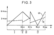
- FIG. 3 represents diagrams of variation of a rotor current IR and a rotor voltage UR of this machine as a function of its speed N plotted on the abscissa. She also shows the succession of operating modes of this machine.
- the static frequency converter 2 is of the type voltage source inverter or current source inverter or still cycloconverter and can include different types semiconductors: transistors, bipolar or IGBT or a Another type; thyristors or thyristors GTO, MCT, etc ...
- the contactors 4a and 4b of the assembly 4 are by example of the conventional mechanical type and in this case it is useful to provide an interlocking preventing the short circuit stator windings simultaneously with the supply of these by the network. They can also be static type using thyristors with switching forced or GTO type thyristors or any other semiconductors performing the closing function and opening of electrical circuits.
- Contactors 4a, 4b are controlled by a circuit electronic (not shown) so as to be actuated simultaneously and in opposition to short-circuit the stator windings or connect them to the electrical network 8 when the machine reaches a predetermined speed special.
- these contactors are of the type static when the machine frequently goes through this particular predetermined speed value at during its operation. They are for example made up thyristors, the stator windings being of the type phase. Like the other parts of the machine, they are shown in single line diagram in Figure 1. They can be of another nature, transistor for example, and then be ordered all or nothing, i.e. at full opening or blocked or they can be ordered with a variable ignition angle relative to the phase of the sine waves of the network or set 1, allowing thus an adjustment of the stator voltage or current.
- the number of poles depends on the speed of the machine and the stator and rotor frequencies chosen according to the supply network and the type of static converter used.
- the values to be given to the machine transformation ratio are determined, on the one hand, by the total excursion of the mechanical rotation speed around the synchronization speed, and on the other hand, by the design voltage of the converter static.
- stator windings are short-circuited by assembly 4 (contactor 4a in the state open not passing and contactor 4b in the closed passing state).
- the rotor windings are supplied with voltage by the network 8 through converter 2.
- mode I This first phase of machine operation, is hereinafter called mode I.
- mode II we eliminates the short circuit of the stator windings and we connects the stator windings to the network 8.
- This switching is carried out by the contactors of set 4 (contactor 4a brought to the closed closed state and contactor 4b brought to the open state not passing).
- these contactors are controlled by electronic circuitry not shown which compares the speed of the machine to the particular predetermined speed and which is also arranged to perform switching during phase matching stator and network voltages for coupling purposes.
- switching may only last a few milliseconds.
- mode III after switching and synchronization of mode II, the frequency of the converter to increase the machine speed of the speed Nmin up to a speed Ntrs defined by the type of charge.
- the speed Ntrs is therefore between Nmin and Nmax. Passing through the synchronism speed Nsyn (function of the number of poles and the frequency of the network) the rotor is powered by direct current. In modes III and IV, the static converter imposes on the rotor a rotor frequency equal to the difference between the network frequency and the frequency corresponding to the speed of the machine.
- the converter returns to the network 8 of the so-called electrical energy sliding of main assembly 1 with respect to speed Nsyn.
- converter 2 supplies the rotor in direct currents.
- converter 2 provides power to the machine, through the rotor, and this proportional to the slip compared to the speed Nsyn.
- stator ES and rotor ER windings are three-phase type.
- the stator windings are invariable.
- the adaptation device 10 of the machine makes it possible to give to the group of windings ER of the rotor R a first and a second configurations respectively giving a first value and a second value to the transformation ratio of the machine.
- each phase of the windings rotor have two identical coils 11 and 12.
- a switch 13 controlled by the speed of the machine allows to converter 2 to supply either the two coils in series, or only the coil 11, the coil 12 then being placed in open circuit.
- the doubling thus achieved of the ratio of transformation of the machine seems particularly suitable in the case where the shaft AB is coupled to a load 3 whose torque resistant is proportional to the square of the speed of the machine.
- a variant of the process described above can be made by reversing the stator and the rotor.
- the stator is then powered by the converter and the rotor is first short-circuited, then coupled on the network.
Landscapes
- Engineering & Computer Science (AREA)
- Power Engineering (AREA)
- Combustion & Propulsion (AREA)
- Sustainable Development (AREA)
- Sustainable Energy (AREA)
- Chemical & Material Sciences (AREA)
- Life Sciences & Earth Sciences (AREA)
- Mechanical Engineering (AREA)
- General Engineering & Computer Science (AREA)
- Control Of Ac Motors In General (AREA)
- Control Of Eletrric Generators (AREA)
- Control Of Multiple Motors (AREA)
- Wind Motors (AREA)
- Synchronous Machinery (AREA)
Applications Claiming Priority (3)
| Application Number | Priority Date | Filing Date | Title |
|---|---|---|---|
| FR9609450A FR2751806B1 (fr) | 1996-07-26 | 1996-07-26 | Procede de commande d'une machine electrique tournante a double alimentation et machine utilisant ce procede |
| FR9609450 | 1996-07-26 | ||
| EP97401722A EP0821467B1 (de) | 1996-07-26 | 1997-07-17 | Steuerungsverfahren für eine zweifach gespeiste Drehfeldmaschine und Maschine, die dieses Verfahren benützt |
Related Parent Applications (2)
| Application Number | Title | Priority Date | Filing Date |
|---|---|---|---|
| EP97401722A Division EP0821467B1 (de) | 1996-07-26 | 1997-07-17 | Steuerungsverfahren für eine zweifach gespeiste Drehfeldmaschine und Maschine, die dieses Verfahren benützt |
| EP97401722.0 Division | 1997-07-17 |
Publications (3)
| Publication Number | Publication Date |
|---|---|
| EP1302659A2 true EP1302659A2 (de) | 2003-04-16 |
| EP1302659A3 EP1302659A3 (de) | 2003-04-23 |
| EP1302659B1 EP1302659B1 (de) | 2006-04-05 |
Family
ID=9494530
Family Applications (2)
| Application Number | Title | Priority Date | Filing Date |
|---|---|---|---|
| EP97401722A Expired - Lifetime EP0821467B1 (de) | 1996-07-26 | 1997-07-17 | Steuerungsverfahren für eine zweifach gespeiste Drehfeldmaschine und Maschine, die dieses Verfahren benützt |
| EP03000860A Expired - Lifetime EP1302659B1 (de) | 1996-07-26 | 1997-07-17 | Regelverfahren für eine Windmühle |
Family Applications Before (1)
| Application Number | Title | Priority Date | Filing Date |
|---|---|---|---|
| EP97401722A Expired - Lifetime EP0821467B1 (de) | 1996-07-26 | 1997-07-17 | Steuerungsverfahren für eine zweifach gespeiste Drehfeldmaschine und Maschine, die dieses Verfahren benützt |
Country Status (6)
| Country | Link |
|---|---|
| EP (2) | EP0821467B1 (de) |
| JP (1) | JPH1080189A (de) |
| AT (2) | ATE322758T1 (de) |
| DE (2) | DE69735651T2 (de) |
| ES (2) | ES2261798T3 (de) |
| FR (1) | FR2751806B1 (de) |
Cited By (1)
| Publication number | Priority date | Publication date | Assignee | Title |
|---|---|---|---|---|
| US9273668B2 (en) | 2009-03-05 | 2016-03-01 | General Electric Company | Yaw system for a windmill |
Families Citing this family (4)
| Publication number | Priority date | Publication date | Assignee | Title |
|---|---|---|---|---|
| EP1416626A3 (de) * | 2002-10-31 | 2005-12-21 | Alstom | Drehstrommotor mit einem Schleifringläufer und damit ausgestattete Transportanlage |
| WO2009043943A1 (es) * | 2007-10-01 | 2009-04-09 | Ingeteam Energy, S.A. | Método de acoplamiento y regulación de potencia reactiva por estátor para generadores eólicos doblemente alimentados en cualquier condición de viento |
| CN101510702B (zh) * | 2009-03-27 | 2011-09-14 | 华中科技大学 | 一种绕线转子无刷双馈电机 |
| US10340829B2 (en) | 2016-07-25 | 2019-07-02 | General Electric Company | Electrical power circuit and method of operating same |
Family Cites Families (7)
| Publication number | Priority date | Publication date | Assignee | Title |
|---|---|---|---|---|
| DE558171C (de) * | 1932-09-02 | Bbc Brown Boveri & Cie | Doppelt gespeiste Induktionsmaschine | |
| DE645828C (de) * | 1937-06-03 | Mueller Novo Motorenbau G M B | Anlassverfahren fuer Wechselstromdoppellaeufermotoren | |
| GB2054975A (en) * | 1979-07-27 | 1981-02-18 | English Electric Co Ltd | Alternating current generating equipment |
| US4388579A (en) * | 1981-07-17 | 1983-06-14 | The United States Of America As Represented By The United States Department Of Energy | Control system for a wound-rotor motor |
| JPS61177195A (ja) * | 1985-01-31 | 1986-08-08 | Toshiba Corp | セルビウス装置 |
| NO893662L (no) * | 1988-09-30 | 1990-04-02 | Asea Brown Boveri | Synkronmaskin med en tilleggsmagnetiseringsinnretning. |
| JPH02111292A (ja) * | 1988-10-17 | 1990-04-24 | Toshiba Corp | 交流可変速駆動装置 |
-
1996
- 1996-07-26 FR FR9609450A patent/FR2751806B1/fr not_active Expired - Fee Related
-
1997
- 1997-07-17 AT AT03000860T patent/ATE322758T1/de not_active IP Right Cessation
- 1997-07-17 ES ES03000860T patent/ES2261798T3/es not_active Expired - Lifetime
- 1997-07-17 AT AT97401722T patent/ATE242929T1/de not_active IP Right Cessation
- 1997-07-17 DE DE69735651T patent/DE69735651T2/de not_active Expired - Lifetime
- 1997-07-17 EP EP97401722A patent/EP0821467B1/de not_active Expired - Lifetime
- 1997-07-17 DE DE69722723T patent/DE69722723T2/de not_active Expired - Fee Related
- 1997-07-17 ES ES97401722T patent/ES2200134T3/es not_active Expired - Lifetime
- 1997-07-17 EP EP03000860A patent/EP1302659B1/de not_active Expired - Lifetime
- 1997-07-25 JP JP9200157A patent/JPH1080189A/ja active Pending
Cited By (1)
| Publication number | Priority date | Publication date | Assignee | Title |
|---|---|---|---|---|
| US9273668B2 (en) | 2009-03-05 | 2016-03-01 | General Electric Company | Yaw system for a windmill |
Also Published As
| Publication number | Publication date |
|---|---|
| DE69722723T2 (de) | 2004-04-29 |
| JPH1080189A (ja) | 1998-03-24 |
| EP0821467A1 (de) | 1998-01-28 |
| FR2751806B1 (fr) | 1998-09-11 |
| EP0821467B1 (de) | 2003-06-11 |
| EP1302659A3 (de) | 2003-04-23 |
| ATE242929T1 (de) | 2003-06-15 |
| ES2200134T3 (es) | 2004-03-01 |
| ES2261798T3 (es) | 2006-11-16 |
| ATE322758T1 (de) | 2006-04-15 |
| EP1302659B1 (de) | 2006-04-05 |
| FR2751806A1 (fr) | 1998-01-30 |
| DE69735651D1 (de) | 2006-05-18 |
| DE69735651T2 (de) | 2006-08-24 |
| DE69722723D1 (de) | 2003-07-17 |
Similar Documents
| Publication | Publication Date | Title |
|---|---|---|
| US9548605B2 (en) | Protection circuits and methods for electrical machines | |
| EP3520209B1 (de) | Mit einer elektrischen maschine ausgestattetes flugzeugturboprop | |
| FR3052307B1 (fr) | Demarreur generateur sans balais | |
| EP1609226B1 (de) | Elektrischer synchronmotor mit einem stator und mindestens einem rotor und assoziierte steuereinrichtung | |
| EP0260176A1 (de) | Steuerungsverfahren für eine reversible, elektrische Generator-Motor-Maschine eines Kraftfahrzeuges und Anwendung eines solchen Verfahrens | |
| CH616784A5 (de) | ||
| EP3365970A1 (de) | Generatorstarter einer turbomaschine mit asynchroner elektrischer maschine mit mehreren windungen | |
| EP0821467B1 (de) | Steuerungsverfahren für eine zweifach gespeiste Drehfeldmaschine und Maschine, die dieses Verfahren benützt | |
| FR2881896A1 (fr) | Systeme de generation electrique a frequence fixe a coupleur a induction et utilisation de celui-ci dans un aeronef | |
| EP2961060B1 (de) | Elektrisches Versorgungssystem einer Last und entsprechendes Versorgungsverfahren | |
| EP2546976B1 (de) | Verfahren zum verbinden eines laufenden Motors an einen Frequenzumrichter | |
| EP2239830B1 (de) | Wechselstrominduktionsmotor | |
| WO2011013093A1 (fr) | Ensemble comportant un systeme de commutation, une machine synchrone et un variateur | |
| CA2889246C (fr) | Systeme electromecanique d'actionnement et/ou generation, comprenant une isolation electrique entre la source electrique et le consommateur | |
| EP1775823A2 (de) | Elektrische Maschine | |
| FR3149934A1 (fr) | Démarreur-générateur à fonction démarreur améliorée | |
| FR3042926A1 (fr) | Procede et dispositif de commande d'une machine tournante electrique | |
| FR2714774A1 (fr) | Procédé d'augmentation du couple d'un moteur asynchrone à double bobinage. | |
| FR3122788A1 (fr) | Bobinage en fonction d’une typologie d’une machine électrique tournante synchrone à aimant pour dispositif mobile à autopropulsion | |
| FR3093876A1 (fr) | Système configuré pour délivrer un courant polyphasé de fréquence constante à partir d’une génératrice synchrone | |
| BE728725A (de) | ||
| EP0795434A1 (de) | Fahrzeug mit elektrischem Synchronmotor | |
| BE350986A (de) | ||
| BE552078A (de) | ||
| BE376870A (de) |
Legal Events
| Date | Code | Title | Description |
|---|---|---|---|
| PUAI | Public reference made under article 153(3) epc to a published international application that has entered the european phase |
Free format text: ORIGINAL CODE: 0009012 |
|
| PUAL | Search report despatched |
Free format text: ORIGINAL CODE: 0009013 |
|
| 17P | Request for examination filed |
Effective date: 20030115 |
|
| AC | Divisional application: reference to earlier application |
Ref document number: 0821467 Country of ref document: EP Kind code of ref document: P |
|
| AK | Designated contracting states |
Designated state(s): AT CH DE ES GB IT LI SE |
|
| AK | Designated contracting states |
Designated state(s): AT CH DE ES GB IT LI SE |
|
| RAP1 | Party data changed (applicant data changed or rights of an application transferred) |
Owner name: ALSTOM POWER CONVERSION GMBH |
|
| RIN1 | Information on inventor provided before grant (corrected) |
Inventor name: GODFROID, HENRI Inventor name: MIRZAIAN, ABDULLAH Inventor name: MOREL, LAURENT |
|
| AKX | Designation fees paid |
Designated state(s): AT CH DE ES GB IT LI SE |
|
| 17Q | First examination report despatched |
Effective date: 20050202 |
|
| GRAP | Despatch of communication of intention to grant a patent |
Free format text: ORIGINAL CODE: EPIDOSNIGR1 |
|
| GRAS | Grant fee paid |
Free format text: ORIGINAL CODE: EPIDOSNIGR3 |
|
| GRAA | (expected) grant |
Free format text: ORIGINAL CODE: 0009210 |
|
| RIC1 | Information provided on ipc code assigned before grant |
Ipc: H02P 27/05 20060101ALI20060208BHEP Ipc: H02P 23/00 20060101AFI20060208BHEP |
|
| AC | Divisional application: reference to earlier application |
Ref document number: 0821467 Country of ref document: EP Kind code of ref document: P |
|
| AK | Designated contracting states |
Kind code of ref document: B1 Designated state(s): AT CH DE ES GB IT LI SE |
|
| PG25 | Lapsed in a contracting state [announced via postgrant information from national office to epo] |
Ref country code: IT Free format text: LAPSE BECAUSE OF FAILURE TO SUBMIT A TRANSLATION OF THE DESCRIPTION OR TO PAY THE FEE WITHIN THE PRESCRIBED TIME-LIMIT;WARNING: LAPSES OF ITALIAN PATENTS WITH EFFECTIVE DATE BEFORE 2007 MAY HAVE OCCURRED AT ANY TIME BEFORE 2007. THE CORRECT EFFECTIVE DATE MAY BE DIFFERENT FROM THE ONE RECORDED. Effective date: 20060405 Ref country code: AT Free format text: LAPSE BECAUSE OF FAILURE TO SUBMIT A TRANSLATION OF THE DESCRIPTION OR TO PAY THE FEE WITHIN THE PRESCRIBED TIME-LIMIT Effective date: 20060405 |
|
| REG | Reference to a national code |
Ref country code: GB Ref legal event code: FG4D Free format text: NOT ENGLISH |
|
| REG | Reference to a national code |
Ref country code: CH Ref legal event code: EP |
|
| GBT | Gb: translation of ep patent filed (gb section 77(6)(a)/1977) |
Effective date: 20060405 |
|
| REF | Corresponds to: |
Ref document number: 69735651 Country of ref document: DE Date of ref document: 20060518 Kind code of ref document: P |
|
| PG25 | Lapsed in a contracting state [announced via postgrant information from national office to epo] |
Ref country code: SE Free format text: LAPSE BECAUSE OF FAILURE TO SUBMIT A TRANSLATION OF THE DESCRIPTION OR TO PAY THE FEE WITHIN THE PRESCRIBED TIME-LIMIT Effective date: 20060705 |
|
| PG25 | Lapsed in a contracting state [announced via postgrant information from national office to epo] |
Ref country code: LI Free format text: LAPSE BECAUSE OF NON-PAYMENT OF DUE FEES Effective date: 20060731 Ref country code: CH Free format text: LAPSE BECAUSE OF NON-PAYMENT OF DUE FEES Effective date: 20060731 |
|
| REG | Reference to a national code |
Ref country code: ES Ref legal event code: FG2A Ref document number: 2261798 Country of ref document: ES Kind code of ref document: T3 |
|
| PLBE | No opposition filed within time limit |
Free format text: ORIGINAL CODE: 0009261 |
|
| STAA | Information on the status of an ep patent application or granted ep patent |
Free format text: STATUS: NO OPPOSITION FILED WITHIN TIME LIMIT |
|
| 26N | No opposition filed |
Effective date: 20070108 |
|
| REG | Reference to a national code |
Ref country code: CH Ref legal event code: PL |
|
| REG | Reference to a national code |
Ref country code: GB Ref legal event code: 732E |
|
| REG | Reference to a national code |
Ref country code: DE Ref legal event code: R082 Ref document number: 69735651 Country of ref document: DE Representative=s name: RUEGER, BARTHELT & ABEL PATENTANWAELTE, DE |
|
| PGFP | Annual fee paid to national office [announced via postgrant information from national office to epo] |
Ref country code: GB Payment date: 20150727 Year of fee payment: 19 Ref country code: DE Payment date: 20150729 Year of fee payment: 19 Ref country code: ES Payment date: 20150727 Year of fee payment: 19 |
|
| REG | Reference to a national code |
Ref country code: DE Ref legal event code: R119 Ref document number: 69735651 Country of ref document: DE |
|
| GBPC | Gb: european patent ceased through non-payment of renewal fee |
Effective date: 20160717 |
|
| PG25 | Lapsed in a contracting state [announced via postgrant information from national office to epo] |
Ref country code: DE Free format text: LAPSE BECAUSE OF NON-PAYMENT OF DUE FEES Effective date: 20170201 |
|
| PG25 | Lapsed in a contracting state [announced via postgrant information from national office to epo] |
Ref country code: GB Free format text: LAPSE BECAUSE OF NON-PAYMENT OF DUE FEES Effective date: 20160717 |
|
| REG | Reference to a national code |
Ref country code: ES Ref legal event code: FD2A Effective date: 20180507 |
|
| PG25 | Lapsed in a contracting state [announced via postgrant information from national office to epo] |
Ref country code: ES Free format text: LAPSE BECAUSE OF NON-PAYMENT OF DUE FEES Effective date: 20160718 |