EP1302691A2 - Naben-Bremsrotoreinheit für ein Fahrzeugrad - Google Patents
Naben-Bremsrotoreinheit für ein Fahrzeugrad Download PDFInfo
- Publication number
- EP1302691A2 EP1302691A2 EP02021536A EP02021536A EP1302691A2 EP 1302691 A2 EP1302691 A2 EP 1302691A2 EP 02021536 A EP02021536 A EP 02021536A EP 02021536 A EP02021536 A EP 02021536A EP 1302691 A2 EP1302691 A2 EP 1302691A2
- Authority
- EP
- European Patent Office
- Prior art keywords
- hub
- flange
- brake rotor
- radial
- bearing
- Prior art date
- Legal status (The legal status is an assumption and is not a legal conclusion. Google has not performed a legal analysis and makes no representation as to the accuracy of the status listed.)
- Granted
Links
Images

Classifications
-
- F—MECHANICAL ENGINEERING; LIGHTING; HEATING; WEAPONS; BLASTING
- F16—ENGINEERING ELEMENTS AND UNITS; GENERAL MEASURES FOR PRODUCING AND MAINTAINING EFFECTIVE FUNCTIONING OF MACHINES OR INSTALLATIONS; THERMAL INSULATION IN GENERAL
- F16C—SHAFTS; FLEXIBLE SHAFTS; ELEMENTS OR CRANKSHAFT MECHANISMS; ROTARY BODIES OTHER THAN GEARING ELEMENTS; BEARINGS
- F16C19/00—Bearings with rolling contact, for exclusively rotary movement
- F16C19/02—Bearings with rolling contact, for exclusively rotary movement with bearing balls essentially of the same size in one or more circular rows
- F16C19/14—Bearings with rolling contact, for exclusively rotary movement with bearing balls essentially of the same size in one or more circular rows for both radial and axial load
- F16C19/18—Bearings with rolling contact, for exclusively rotary movement with bearing balls essentially of the same size in one or more circular rows for both radial and axial load with two or more rows of balls
- F16C19/181—Bearings with rolling contact, for exclusively rotary movement with bearing balls essentially of the same size in one or more circular rows for both radial and axial load with two or more rows of balls with angular contact
- F16C19/183—Bearings with rolling contact, for exclusively rotary movement with bearing balls essentially of the same size in one or more circular rows for both radial and axial load with two or more rows of balls with angular contact with two rows at opposite angles
- F16C19/184—Bearings with rolling contact, for exclusively rotary movement with bearing balls essentially of the same size in one or more circular rows for both radial and axial load with two or more rows of balls with angular contact with two rows at opposite angles in O-arrangement
-
- F—MECHANICAL ENGINEERING; LIGHTING; HEATING; WEAPONS; BLASTING
- F16—ENGINEERING ELEMENTS AND UNITS; GENERAL MEASURES FOR PRODUCING AND MAINTAINING EFFECTIVE FUNCTIONING OF MACHINES OR INSTALLATIONS; THERMAL INSULATION IN GENERAL
- F16C—SHAFTS; FLEXIBLE SHAFTS; ELEMENTS OR CRANKSHAFT MECHANISMS; ROTARY BODIES OTHER THAN GEARING ELEMENTS; BEARINGS
- F16C35/00—Rigid support of bearing units; Housings, e.g. caps, covers
- F16C35/04—Rigid support of bearing units; Housings, e.g. caps, covers in the case of ball or roller bearings
- F16C35/06—Mounting or dismounting of ball or roller bearings; Fixing them onto shaft or in housing
- F16C35/067—Fixing them in a housing
-
- F—MECHANICAL ENGINEERING; LIGHTING; HEATING; WEAPONS; BLASTING
- F16—ENGINEERING ELEMENTS AND UNITS; GENERAL MEASURES FOR PRODUCING AND MAINTAINING EFFECTIVE FUNCTIONING OF MACHINES OR INSTALLATIONS; THERMAL INSULATION IN GENERAL
- F16D—COUPLINGS FOR TRANSMITTING ROTATION; CLUTCHES; BRAKES
- F16D65/00—Parts or details
- F16D65/02—Braking members; Mounting thereof
- F16D65/12—Discs; Drums for disc brakes
-
- F—MECHANICAL ENGINEERING; LIGHTING; HEATING; WEAPONS; BLASTING
- F16—ENGINEERING ELEMENTS AND UNITS; GENERAL MEASURES FOR PRODUCING AND MAINTAINING EFFECTIVE FUNCTIONING OF MACHINES OR INSTALLATIONS; THERMAL INSULATION IN GENERAL
- F16C—SHAFTS; FLEXIBLE SHAFTS; ELEMENTS OR CRANKSHAFT MECHANISMS; ROTARY BODIES OTHER THAN GEARING ELEMENTS; BEARINGS
- F16C2326/00—Articles relating to transporting
- F16C2326/01—Parts of vehicles in general
- F16C2326/02—Wheel hubs or castors
-
- F—MECHANICAL ENGINEERING; LIGHTING; HEATING; WEAPONS; BLASTING
- F16—ENGINEERING ELEMENTS AND UNITS; GENERAL MEASURES FOR PRODUCING AND MAINTAINING EFFECTIVE FUNCTIONING OF MACHINES OR INSTALLATIONS; THERMAL INSULATION IN GENERAL
- F16D—COUPLINGS FOR TRANSMITTING ROTATION; CLUTCHES; BRAKES
- F16D65/00—Parts or details
- F16D65/02—Braking members; Mounting thereof
- F16D2065/13—Parts or details of discs or drums
- F16D2065/1304—Structure
- F16D2065/1316—Structure radially segmented
-
- F—MECHANICAL ENGINEERING; LIGHTING; HEATING; WEAPONS; BLASTING
- F16—ENGINEERING ELEMENTS AND UNITS; GENERAL MEASURES FOR PRODUCING AND MAINTAINING EFFECTIVE FUNCTIONING OF MACHINES OR INSTALLATIONS; THERMAL INSULATION IN GENERAL
- F16D—COUPLINGS FOR TRANSMITTING ROTATION; CLUTCHES; BRAKES
- F16D65/00—Parts or details
- F16D65/02—Braking members; Mounting thereof
- F16D2065/13—Parts or details of discs or drums
- F16D2065/134—Connection
- F16D2065/1344—Connection permanent, e.g. by casting
-
- F—MECHANICAL ENGINEERING; LIGHTING; HEATING; WEAPONS; BLASTING
- F16—ENGINEERING ELEMENTS AND UNITS; GENERAL MEASURES FOR PRODUCING AND MAINTAINING EFFECTIVE FUNCTIONING OF MACHINES OR INSTALLATIONS; THERMAL INSULATION IN GENERAL
- F16D—COUPLINGS FOR TRANSMITTING ROTATION; CLUTCHES; BRAKES
- F16D65/00—Parts or details
- F16D65/02—Braking members; Mounting thereof
- F16D2065/13—Parts or details of discs or drums
- F16D2065/134—Connection
- F16D2065/1384—Connection to wheel hub
-
- F—MECHANICAL ENGINEERING; LIGHTING; HEATING; WEAPONS; BLASTING
- F16—ENGINEERING ELEMENTS AND UNITS; GENERAL MEASURES FOR PRODUCING AND MAINTAINING EFFECTIVE FUNCTIONING OF MACHINES OR INSTALLATIONS; THERMAL INSULATION IN GENERAL
- F16D—COUPLINGS FOR TRANSMITTING ROTATION; CLUTCHES; BRAKES
- F16D2250/00—Manufacturing; Assembly
-
- F—MECHANICAL ENGINEERING; LIGHTING; HEATING; WEAPONS; BLASTING
- F16—ENGINEERING ELEMENTS AND UNITS; GENERAL MEASURES FOR PRODUCING AND MAINTAINING EFFECTIVE FUNCTIONING OF MACHINES OR INSTALLATIONS; THERMAL INSULATION IN GENERAL
- F16D—COUPLINGS FOR TRANSMITTING ROTATION; CLUTCHES; BRAKES
- F16D2250/00—Manufacturing; Assembly
- F16D2250/0092—Tools or machines for producing linings
Definitions
- the present invention relates to a hub and brake rotor assembly for a vehicle wheel, of a type including a so-called first generation hub and bearing unit and a brake rotor, such as a disc or a drum, connected to the hub so as to be rotatable therewith, as specified in Claim 1.
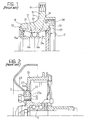
- a first-generation hub and bearing unit for a vehicle wheel assembly includes a radially outer annular hub 10 and a bearing 11.
- the hub 10 has an outer radial flange 12, with a plurality of axial holes 13 formed therein for fixing a wheel to a vehicle, and an axial cylindrical seat with the bearing 11 mounted therein.
- the bearing 11 includes two rings of rolling elements 15a and 15b, in this example taper rollers, interposed radially between a pair of radially inner rings or half-rings 16a and 16b and a radially outer ring 17.
- the non-rotating inner rings 16a and 16b of the bearing 11 are locked against rotation onto the wheel shaft (not shown), while the outer ring 17 is housed in the cylindrical seat 14 in the hub for rotation therewith.
- the seat 14 extends between two radial surfaces 18 and 19, facing inwardly and outwardly of the vehicle respectively.
- the outer ring 17 of the bearing 11 includes a main, central annular portion 20 in which the raceways for the rolling elements 15a and 15b are formed.
- the outer ring 17 has an outer cylindrical surface 21 for fitting into the cylindrical seat 14 in the hub 10.
- the dimensions of the cylindrical seat 14 and the cylindrical surface 21 are such that a certain amount of radial interference is involved, requiring the bearing to be force-fitted into the hub, and thereby improving the axial and circumferential locking of the outer ring of the bearing in the hub.
- the outer cylindrical surface 21 extends over the entire axial dimension of the outer ring 17 and the axial width thereof is greater than that of the seat 14.
- the two axially opposite ends of the main, central portion 20 of the outer ring 17 have respective annular formations 22 and 23, formed by cold deformation, usually by rolling, in such a way that they project axially beyond the lateral surfaces 18 and 19 of the annular hub 10 and can be bent radially outwards against these opposite lateral surfaces in order to lock the ring 17 to the hub 10.
- the outer ring 17 of the bearing 11 has only one tubular projection 22 which extends axially on the axially inward side of the ring, while the axially outward side has an axial shoulder bearing against the lateral surface 19 of the hub.
- a brake rotor (not shown in Figure 1) is fitted on the hub 10 by bolts screwed into axial threaded holes 24 in the hub 10.
- the present invention also relates to a hub and brake rotor assembly in which the brake rotor is coupled to the hub by cold-deformation, by rolling for example.
- An assembly of this type is described in European Patent EP-B-0 783 980, from which Figure 2 of the appended drawings was extracted.
- a hub and bearing assembly of the so-called second generation type includes an annular hub 10 with an external radial flange 12 with axial holes 13 for fixing a wheel 25 to the vehicle.
- a brake rotor 26 such as a disc or a drum, has an inner radial flange 27, arranged in the same radial plane as the flange 12 of the hub 10 so as to be fixed directly to the periphery thereof.
- the brake rotor 26 is coupled for rotation with the hub 10 by radial interference between the two external cylindrical surfaces 12a and 27a on the radial flanges 12 and 27 respectively of the two elements, and is locked axially on the hub 10 between a shoulder 28 and a rolled edge 29, formed at the axially outward and inward ends respectively of the surface 12a of the hub.
- the object of the invention is to provide a hub and brake rotor assembly which improves on the prior art, which can be manufactured at a lower cost, which is easy and rapid to assemble and which ensures improved and more reliable operation.
- a hub and brake rotor assembly according to the present invention essentially includes:
- the hub and brake rotor assembly of the invention also provides for alternative embodiments (not shown), which differ from that described above by the means for fixing the hub 10 to the outer ring 17 of the bearing 11 and/or for fixing the brake rotor 26 to the flange 12 of the hub 10.
- fixing the brake rotor 26 to the hub 10 it is possible to lock both sides of the flange 27 of the rotor onto the flange 12 of the hub by means of annular rims formed by rolling.
- the scope of the invention also includes an embodiment where, in order to lock the hub 10 axially onto the bearing 11, one or more rolled edges are formed on the hub rather than on the outer ring 17 of the bearing and another in which, in order to lock the brake rotor 26 axially on the hub 10, one or more rolled edges are provided on the rotor rather than on the hub.
- the scope of the invention also includes an embodiment where, in order to lock the hub 10 axially onto the bearing 11, one or more rolled edges are formed on the hub rather than on the outer ring 17 of the bearing and another in which, in order to lock the brake rotor 26 axially on the hub 10, one or more rolled edges are provided on the rotor rather than on the hub.
- a hub and rotor assembly according to the invention is made up of a small number of parts, thanks to the fact that the fixings securing the brake rotor to the hub and the hub to the bearing are formed by rolling and not by threaded fixing means, as in the prior art. This makes it easier to manage the components needing to be assembled during a manufacturing cycle. In addition, in the case of large-scale production, such as that intended for the automobile industry, fixing by rolling proves more economical compared to the conventional method of threaded connection.
- a further advantage provided by the invention consists in the fact that, since the coupling surfaces between the brake rotor and the hub (constituted essentially by the cylindrical lateral surfaces 12a and 27a of the flanges 12 and 27) are smaller than they are when the rotor is coupled to the flange by bolts, the rotor transmits less heat to the bearing-hub unit, which thus operates in more favourable thermal conditions.
- the flange of the brake rotor can be of smaller dimensions than those the prior art, thus saving on material which involves a reduction in the overall weight of the wheel assembly as well as into lower manufacturing costs for the brake rotor.
- the rolled coupling between the brake rotor and the hub also means the axial dimensions of the wheel assembly can be kept down, allowing for greater flexibility in applying the assembly in different lay-outs.
Landscapes
- Engineering & Computer Science (AREA)
- General Engineering & Computer Science (AREA)
- Mechanical Engineering (AREA)
- Braking Arrangements (AREA)
- Rolling Contact Bearings (AREA)
Applications Claiming Priority (2)
| Application Number | Priority Date | Filing Date | Title |
|---|---|---|---|
| IT2001TO000188U ITTO20010188U1 (it) | 2001-10-10 | 2001-10-10 | Gruppo mozzo e rotore di frenatura per una ruota di un veicolo. |
| ITTO20010188U | 2001-10-10 |
Publications (3)
| Publication Number | Publication Date |
|---|---|
| EP1302691A2 true EP1302691A2 (de) | 2003-04-16 |
| EP1302691A3 EP1302691A3 (de) | 2004-05-19 |
| EP1302691B1 EP1302691B1 (de) | 2006-04-12 |
Family
ID=11458647
Family Applications (1)
| Application Number | Title | Priority Date | Filing Date |
|---|---|---|---|
| EP02021536A Expired - Lifetime EP1302691B1 (de) | 2001-10-10 | 2002-09-26 | Naben-Bremsrotoreinheit für ein Fahrzeugrad |
Country Status (6)
| Country | Link |
|---|---|
| US (1) | US6821022B2 (de) |
| EP (1) | EP1302691B1 (de) |
| JP (1) | JP3952458B2 (de) |
| AT (1) | ATE323241T1 (de) |
| DE (1) | DE60210560T2 (de) |
| IT (1) | ITTO20010188U1 (de) |
Cited By (1)
| Publication number | Priority date | Publication date | Assignee | Title |
|---|---|---|---|---|
| EP2354477A3 (de) * | 2010-01-27 | 2012-04-04 | Schaeffler Technologies AG & Co. KG | Nockenwelle mit Wälzlager, Montageanordnung für eine Nockenwelle mit Wälzlager und Verfahren zur Fertigung |
Families Citing this family (5)
| Publication number | Priority date | Publication date | Assignee | Title |
|---|---|---|---|---|
| DE102004055205A1 (de) * | 2004-11-16 | 2006-05-18 | Fag Kugelfischer Ag & Co. Ohg | Einheit aus wenigstens einem Träger und aus einem Radlager |
| US7610999B2 (en) * | 2005-08-30 | 2009-11-03 | Robert Bosch Gmbh | Wheel hub |
| US8083598B2 (en) * | 2006-07-11 | 2011-12-27 | Ntn Corporation | Bearing device for wheel |
| FR2978514B1 (fr) * | 2011-07-26 | 2014-01-24 | Saint Jean Ind | Frein a disque pour vehicule et procede d'assemblage de ses composants |
| DE102019213751A1 (de) * | 2019-01-11 | 2020-07-16 | Continental Teves Ag & Co. Ohg | Gebaute Verbundbremstrommel für ein Kraftfahrzeug |
Family Cites Families (7)
| Publication number | Priority date | Publication date | Assignee | Title |
|---|---|---|---|---|
| IT1284314B1 (it) * | 1996-01-11 | 1998-05-18 | Skf Ind Spa | Gruppo cuscinetto per mozzo ruota di veicolo. |
| IT1288795B1 (it) * | 1996-10-31 | 1998-09-24 | Skf Ind Spa | Gruppo cuscinetto per mozzo ruota di veicolo adatto al collegamento con l'organo frenante per formatura a freddo. |
| IT1291044B1 (it) * | 1997-02-21 | 1998-12-14 | Skf Ind Spa | Configurazione per l'accoppiamento del freno al gruppo cuscinetto/ mozzo di una ruota di veicolo. |
| DE19742027C2 (de) * | 1997-09-24 | 2001-08-30 | Fischer Georg Fahrzeugtech | Radlagerung für Kraftfahrzeugräder |
| IT1308389B1 (it) * | 1999-02-24 | 2001-12-17 | Skf Ind Spa | Cuscinetto per il mozzo della ruota di un autoveicolo e procedimentoper il montaggio del cuscinetto sulla sospensione di un autoveicolo. |
| FR2810382B1 (fr) * | 2000-06-16 | 2002-08-30 | Peugeot Citroen Automobiles Sa | Dispositif d'assemblage d'un element rotatif d'un mecanisme de frein avec un moyen de roue de vehicule |
| IT1320569B1 (it) | 2000-07-31 | 2003-12-10 | Skf Ind Spa | Gruppo cuscinetto-mozzo per una ruota di un veicolo a motore. |
-
2001
- 2001-10-10 IT IT2001TO000188U patent/ITTO20010188U1/it unknown
-
2002
- 2002-09-26 EP EP02021536A patent/EP1302691B1/de not_active Expired - Lifetime
- 2002-09-26 AT AT02021536T patent/ATE323241T1/de not_active IP Right Cessation
- 2002-09-26 DE DE60210560T patent/DE60210560T2/de not_active Expired - Lifetime
- 2002-10-08 US US10/267,626 patent/US6821022B2/en not_active Expired - Lifetime
- 2002-10-10 JP JP2002296946A patent/JP3952458B2/ja not_active Expired - Fee Related
Non-Patent Citations (1)
| Title |
|---|
| None |
Cited By (1)
| Publication number | Priority date | Publication date | Assignee | Title |
|---|---|---|---|---|
| EP2354477A3 (de) * | 2010-01-27 | 2012-04-04 | Schaeffler Technologies AG & Co. KG | Nockenwelle mit Wälzlager, Montageanordnung für eine Nockenwelle mit Wälzlager und Verfahren zur Fertigung |
Also Published As
| Publication number | Publication date |
|---|---|
| DE60210560T2 (de) | 2006-11-09 |
| EP1302691A3 (de) | 2004-05-19 |
| JP3952458B2 (ja) | 2007-08-01 |
| US6821022B2 (en) | 2004-11-23 |
| DE60210560D1 (de) | 2006-05-24 |
| ATE323241T1 (de) | 2006-04-15 |
| US20030068109A1 (en) | 2003-04-10 |
| ITTO20010188U1 (it) | 2003-04-10 |
| EP1302691B1 (de) | 2006-04-12 |
| JP2003139173A (ja) | 2003-05-14 |
Similar Documents
| Publication | Publication Date | Title |
|---|---|---|
| EP0794072B1 (de) | Verfahren zum Zusammenbau einer Nabe mit einem Lager eines Fahrzeugrades mit einer entsprechenden Stütze und daraus resultierende Radlager-Einheit | |
| EP1127713B1 (de) | Radlagereinheit und Verfahren zu deren Herstellung | |
| EP0860626B1 (de) | Verbindung zwischen einer Radnaben-Lagereinheit und einem Bremsrotor | |
| US8267593B2 (en) | Bearing apparatus for a wheel of vehicle | |
| US20010019640A1 (en) | Automotive wheel bearing assembly and method for manufacturing the same | |
| US20030077016A1 (en) | Connection of a wheel hub bearing unit to a motor vehicle suspension standard | |
| JPH11129703A5 (de) | ||
| US6866422B2 (en) | Bearing-hub unit for motor vehicle wheel | |
| CN101848816A (zh) | 车轮用轴承装置 | |
| US6857835B2 (en) | Wheel end assembly with locking fastener | |
| EP1302691B1 (de) | Naben-Bremsrotoreinheit für ein Fahrzeugrad | |
| EP1302690A2 (de) | Naben-Bremsrotoreinheit für ein Fahrzeugrad | |
| JP2003159908A (ja) | 駆動輪用回転支持装置 | |
| US6886987B2 (en) | Hub-bearing assembly for a driving wheel of a vehicle, particularly a truck | |
| JP2010089664A (ja) | 車輪用軸受装置 | |
| JP4693752B2 (ja) | 車輪用軸受装置の製造方法 | |
| JP2018197598A (ja) | 駆動輪用ハブユニット | |
| JP2004203209A (ja) | 車輪軸受装置 | |
| JP2008030554A (ja) | 車輪用軸受装置 | |
| JP2017094978A (ja) | ハブ輪及び車輪支持用転がり軸受ユニット | |
| JP7619117B2 (ja) | 車輪駆動用ユニット及びその組立方法 | |
| JP2003056580A (ja) | 車軸用軸受装置 | |
| KR101728031B1 (ko) | 휠 베어링 및 그 제작 방법 | |
| US7117600B1 (en) | Process of manufacturing a corner assembly | |
| EP1470936A1 (de) | Lagereinheit für fahrzeugrad |
Legal Events
| Date | Code | Title | Description |
|---|---|---|---|
| PUAI | Public reference made under article 153(3) epc to a published international application that has entered the european phase |
Free format text: ORIGINAL CODE: 0009012 |
|
| AK | Designated contracting states |
Designated state(s): AT BE BG CH CY CZ DE DK EE ES FI FR GB GR IE IT LI LU MC NL PT SE SK TR |
|
| AX | Request for extension of the european patent |
Extension state: AL LT LV MK RO SI |
|
| PUAL | Search report despatched |
Free format text: ORIGINAL CODE: 0009013 |
|
| AK | Designated contracting states |
Kind code of ref document: A3 Designated state(s): AT BE BG CH CY CZ DE DK EE ES FI FR GB GR IE IT LI LU MC NL PT SE SK TR |
|
| AX | Request for extension of the european patent |
Extension state: AL LT LV MK RO SI |
|
| 17P | Request for examination filed |
Effective date: 20041110 |
|
| AKX | Designation fees paid |
Designated state(s): AT BE BG CH CY CZ DE DK EE ES FI FR GB GR IE IT LI LU MC NL PT SE SK TR |
|
| 17Q | First examination report despatched |
Effective date: 20050329 |
|
| GRAP | Despatch of communication of intention to grant a patent |
Free format text: ORIGINAL CODE: EPIDOSNIGR1 |
|
| GRAS | Grant fee paid |
Free format text: ORIGINAL CODE: EPIDOSNIGR3 |
|
| GRAA | (expected) grant |
Free format text: ORIGINAL CODE: 0009210 |
|
| AK | Designated contracting states |
Kind code of ref document: B1 Designated state(s): AT BE BG CH CY CZ DE DK EE ES FI FR GB GR IE IT LI LU MC NL PT SE SK TR |
|
| PG25 | Lapsed in a contracting state [announced via postgrant information from national office to epo] |
Ref country code: AT Free format text: LAPSE BECAUSE OF FAILURE TO SUBMIT A TRANSLATION OF THE DESCRIPTION OR TO PAY THE FEE WITHIN THE PRESCRIBED TIME-LIMIT Effective date: 20060412 Ref country code: CH Free format text: LAPSE BECAUSE OF FAILURE TO SUBMIT A TRANSLATION OF THE DESCRIPTION OR TO PAY THE FEE WITHIN THE PRESCRIBED TIME-LIMIT Effective date: 20060412 Ref country code: SK Free format text: LAPSE BECAUSE OF FAILURE TO SUBMIT A TRANSLATION OF THE DESCRIPTION OR TO PAY THE FEE WITHIN THE PRESCRIBED TIME-LIMIT Effective date: 20060412 Ref country code: LI Free format text: LAPSE BECAUSE OF FAILURE TO SUBMIT A TRANSLATION OF THE DESCRIPTION OR TO PAY THE FEE WITHIN THE PRESCRIBED TIME-LIMIT Effective date: 20060412 Ref country code: FI Free format text: LAPSE BECAUSE OF FAILURE TO SUBMIT A TRANSLATION OF THE DESCRIPTION OR TO PAY THE FEE WITHIN THE PRESCRIBED TIME-LIMIT Effective date: 20060412 Ref country code: NL Free format text: LAPSE BECAUSE OF FAILURE TO SUBMIT A TRANSLATION OF THE DESCRIPTION OR TO PAY THE FEE WITHIN THE PRESCRIBED TIME-LIMIT Effective date: 20060412 Ref country code: BE Free format text: LAPSE BECAUSE OF FAILURE TO SUBMIT A TRANSLATION OF THE DESCRIPTION OR TO PAY THE FEE WITHIN THE PRESCRIBED TIME-LIMIT Effective date: 20060412 Ref country code: CZ Free format text: LAPSE BECAUSE OF FAILURE TO SUBMIT A TRANSLATION OF THE DESCRIPTION OR TO PAY THE FEE WITHIN THE PRESCRIBED TIME-LIMIT Effective date: 20060412 |
|
| REG | Reference to a national code |
Ref country code: GB Ref legal event code: FG4D |
|
| REG | Reference to a national code |
Ref country code: CH Ref legal event code: EP |
|
| REF | Corresponds to: |
Ref document number: 60210560 Country of ref document: DE Date of ref document: 20060524 Kind code of ref document: P |
|
| REG | Reference to a national code |
Ref country code: IE Ref legal event code: FG4D |
|
| PG25 | Lapsed in a contracting state [announced via postgrant information from national office to epo] |
Ref country code: SE Free format text: LAPSE BECAUSE OF FAILURE TO SUBMIT A TRANSLATION OF THE DESCRIPTION OR TO PAY THE FEE WITHIN THE PRESCRIBED TIME-LIMIT Effective date: 20060712 Ref country code: DK Free format text: LAPSE BECAUSE OF FAILURE TO SUBMIT A TRANSLATION OF THE DESCRIPTION OR TO PAY THE FEE WITHIN THE PRESCRIBED TIME-LIMIT Effective date: 20060712 |
|
| PG25 | Lapsed in a contracting state [announced via postgrant information from national office to epo] |
Ref country code: ES Free format text: LAPSE BECAUSE OF FAILURE TO SUBMIT A TRANSLATION OF THE DESCRIPTION OR TO PAY THE FEE WITHIN THE PRESCRIBED TIME-LIMIT Effective date: 20060723 |
|
| PG25 | Lapsed in a contracting state [announced via postgrant information from national office to epo] |
Ref country code: PT Free format text: LAPSE BECAUSE OF FAILURE TO SUBMIT A TRANSLATION OF THE DESCRIPTION OR TO PAY THE FEE WITHIN THE PRESCRIBED TIME-LIMIT Effective date: 20060912 |
|
| PG25 | Lapsed in a contracting state [announced via postgrant information from national office to epo] |
Ref country code: IE Free format text: LAPSE BECAUSE OF NON-PAYMENT OF DUE FEES Effective date: 20060926 |
|
| PG25 | Lapsed in a contracting state [announced via postgrant information from national office to epo] |
Ref country code: MC Free format text: LAPSE BECAUSE OF NON-PAYMENT OF DUE FEES Effective date: 20060930 |
|
| NLV1 | Nl: lapsed or annulled due to failure to fulfill the requirements of art. 29p and 29m of the patents act | ||
| REG | Reference to a national code |
Ref country code: CH Ref legal event code: PL |
|
| PLBE | No opposition filed within time limit |
Free format text: ORIGINAL CODE: 0009261 |
|
| STAA | Information on the status of an ep patent application or granted ep patent |
Free format text: STATUS: NO OPPOSITION FILED WITHIN TIME LIMIT |
|
| 26N | No opposition filed |
Effective date: 20070115 |
|
| EN | Fr: translation not filed | ||
| GBPC | Gb: european patent ceased through non-payment of renewal fee |
Effective date: 20060926 |
|
| PG25 | Lapsed in a contracting state [announced via postgrant information from national office to epo] |
Ref country code: GB Free format text: LAPSE BECAUSE OF NON-PAYMENT OF DUE FEES Effective date: 20060926 |
|
| PG25 | Lapsed in a contracting state [announced via postgrant information from national office to epo] |
Ref country code: FR Free format text: LAPSE BECAUSE OF FAILURE TO SUBMIT A TRANSLATION OF THE DESCRIPTION OR TO PAY THE FEE WITHIN THE PRESCRIBED TIME-LIMIT Effective date: 20070309 Ref country code: GR Free format text: LAPSE BECAUSE OF FAILURE TO SUBMIT A TRANSLATION OF THE DESCRIPTION OR TO PAY THE FEE WITHIN THE PRESCRIBED TIME-LIMIT Effective date: 20060713 |
|
| PG25 | Lapsed in a contracting state [announced via postgrant information from national office to epo] |
Ref country code: BG Free format text: LAPSE BECAUSE OF FAILURE TO SUBMIT A TRANSLATION OF THE DESCRIPTION OR TO PAY THE FEE WITHIN THE PRESCRIBED TIME-LIMIT Effective date: 20060712 Ref country code: EE Free format text: LAPSE BECAUSE OF FAILURE TO SUBMIT A TRANSLATION OF THE DESCRIPTION OR TO PAY THE FEE WITHIN THE PRESCRIBED TIME-LIMIT Effective date: 20060412 |
|
| PG25 | Lapsed in a contracting state [announced via postgrant information from national office to epo] |
Ref country code: LU Free format text: LAPSE BECAUSE OF NON-PAYMENT OF DUE FEES Effective date: 20060926 Ref country code: TR Free format text: LAPSE BECAUSE OF FAILURE TO SUBMIT A TRANSLATION OF THE DESCRIPTION OR TO PAY THE FEE WITHIN THE PRESCRIBED TIME-LIMIT Effective date: 20060412 |
|
| PG25 | Lapsed in a contracting state [announced via postgrant information from national office to epo] |
Ref country code: FR Free format text: LAPSE BECAUSE OF FAILURE TO SUBMIT A TRANSLATION OF THE DESCRIPTION OR TO PAY THE FEE WITHIN THE PRESCRIBED TIME-LIMIT Effective date: 20060412 Ref country code: CY Free format text: LAPSE BECAUSE OF FAILURE TO SUBMIT A TRANSLATION OF THE DESCRIPTION OR TO PAY THE FEE WITHIN THE PRESCRIBED TIME-LIMIT Effective date: 20060412 |
|
| PGFP | Annual fee paid to national office [announced via postgrant information from national office to epo] |
Ref country code: DE Payment date: 20161130 Year of fee payment: 15 |
|
| PGFP | Annual fee paid to national office [announced via postgrant information from national office to epo] |
Ref country code: IT Payment date: 20160922 Year of fee payment: 15 |
|
| REG | Reference to a national code |
Ref country code: DE Ref legal event code: R119 Ref document number: 60210560 Country of ref document: DE |
|
| PG25 | Lapsed in a contracting state [announced via postgrant information from national office to epo] |
Ref country code: DE Free format text: LAPSE BECAUSE OF NON-PAYMENT OF DUE FEES Effective date: 20180404 |
|
| PG25 | Lapsed in a contracting state [announced via postgrant information from national office to epo] |
Ref country code: IT Free format text: LAPSE BECAUSE OF NON-PAYMENT OF DUE FEES Effective date: 20170926 |