EP1302692A2 - Hydraulischer Stossdämpfer - Google Patents
Hydraulischer Stossdämpfer Download PDFInfo
- Publication number
- EP1302692A2 EP1302692A2 EP02020124A EP02020124A EP1302692A2 EP 1302692 A2 EP1302692 A2 EP 1302692A2 EP 02020124 A EP02020124 A EP 02020124A EP 02020124 A EP02020124 A EP 02020124A EP 1302692 A2 EP1302692 A2 EP 1302692A2
- Authority
- EP
- European Patent Office
- Prior art keywords
- shock absorber
- sealing
- seal
- hydraulic shock
- welding
- Prior art date
- Legal status (The legal status is an assumption and is not a legal conclusion. Google has not performed a legal analysis and makes no representation as to the accuracy of the status listed.)
- Granted
Links
Images


Classifications
-
- F—MECHANICAL ENGINEERING; LIGHTING; HEATING; WEAPONS; BLASTING
- F16—ENGINEERING ELEMENTS AND UNITS; GENERAL MEASURES FOR PRODUCING AND MAINTAINING EFFECTIVE FUNCTIONING OF MACHINES OR INSTALLATIONS; THERMAL INSULATION IN GENERAL
- F16F—SPRINGS; SHOCK-ABSORBERS; MEANS FOR DAMPING VIBRATION
- F16F9/00—Springs, vibration-dampers, shock-absorbers, or similarly-constructed movement-dampers using a fluid or the equivalent as damping medium
- F16F9/32—Details
- F16F9/36—Special sealings, including sealings or guides for piston-rods
- F16F9/362—Combination of sealing and guide arrangements for piston rods
- F16F9/363—Combination of sealing and guide arrangements for piston rods the guide being mounted between the piston and the sealing, enabling lubrication of the guide
Definitions
- the invention relates to a hydraulic shock absorber with a shock absorber tube oscillating piston rod in and out, in which the piston rod by means of a sealing and guide unit made of sheet metal opposite the shock absorber tube is sealed and guided, according to the preamble of claim 1.
- Such hydraulic shock absorbers mainly as shock absorbers for motor vehicles used between the wheels and the vehicle body are from the DE 40 30 788 A1 known.
- the sealing and guiding unit described here is already very simple from different sheet metal parts and a sheet metal reinforced seal manufactured.
- a disadvantage of this known sealing and guiding unit must be when assembling the shock absorber many individual parts of the sealing and guide unit one pushed over the piston rod and the other inserted into the shock absorber tube become.
- the connection of the individual parts of the sealing and guiding unit takes place only with the entire assembly of the shock absorber, that is after the DE 40 30 788 A1 after folding the end of the shock absorber tube inwards the sealing and guiding unit.
- the invention is based on the object, on the one hand the sealing and guiding unit to further simplify and secondly the assembly of the sealing and guide unit as such, but also to simplify with the shock absorber.
- the solution according to the invention has the advantage that the sealing and guiding unit is also completely pre-assembled as a sheet metal component and thus during assembly of the shock absorber is not several parts of the sealing and guiding unit must be handled, which significantly simplifies the overall assembly.
- the support part 1 is formed in two parts. It consists of a socket 2 which is connected to its upper edge is surrounded by a disc 3. The disc 3 is supported radially from the inside on the shock absorber tube 4. On the inner diameter of the bushing 2 of the supporting part 1, a guide bush 5 made of a sliding material is arranged. This guide bush 5 is used for radial guidance of the piston rod, not shown.
- This seal 6 is two or more in all exemplary embodiments Multi-lip design and has an overmolded for axial and radial reinforcement or a vulcanized reinforcing plate 7.
- the inside diameter of the Reinforcement plate 7 is slightly larger than the inner diameter of the guide bush 5, so that the piston rod does not rub against the reinforcement plate 7.
- the outer upper surface of the reinforcement plate 7 is not made of the elastic sealing material surround and thus form a contact surface.
- the reinforcement plate 7 can be made of a hard plastic or metal.
- the seal 6 is in one Pressed collar 9 of socket 2.
- the socket 2 is glued to the support plate 8 or preferably by welded on the outside.
- welding residues on the Root of the weld does not get into the working space 13 of the shock absorber, because in the adjoining room, i.e. within the collar 9 of the socket 2, the seal 6 lies and the root of the weld seam opposite the interior of the shock absorber closes.
- the sealing and Guide unit With the welding of bushing 2 and support plate 8, the sealing and Guide unit fully assembled and forms only one component in the other Assembly.
- the disc 3 of the support part 1, which is not welded to the socket 2 or is glued, can not detach from the socket 2, because on the lower outer Diameter of the socket 2, a bead 10 is arranged over which the disc 3 is not can be moved down.
- the sealing and guide unit inserted into the end of the shock absorber tube 4 and placed on this.
- the fully assembled shock absorber is closed by welding the support plate 8 with the shock absorber tube 4. The welding is done from the outside. Between the support plate 8 and the disc 3 remain a substantially sealed Annulus 11. This annulus 11 lies in the root area of the weld seam 12. Should any welding residues loosen at the root of the weld seam 12 be present, they can not in the working space 13 of the shock absorber or in reach the area of the seal 6 or the guide bush 5, since they are in the annular space 11 are included.
- the support member 1 is formed in one piece.
- the Bushing 2 sits directly over a collar 14 up to the outer diameter of the shock absorber tube 4 continues.
- the reinforcement plate 7 is not complete surrounded with sealing material. It remains in the same area as for training 1 free.
- a support plate 8 can be placed on this area hang up.
- the support plate 8 has a smaller diameter than that Support plate 8 according to FIG. 1. It lies in a recess 15 of the supporting part 1.
- the recess 15 is prepared for a weld. Support plate 8 and support part 1 are in this Area welded together from the outside.
- any welding residue that may come off in the root area of the weld can not in the working space 13, the Area of the seal 6 or the guide bush 5 reach because the root area of the Weld seam is closed by the pressed seal 6.
- the support plate 8 to weld to the support member 1 these two parts can also be together be connected by gluing or caulking.
- the supporting part is in the present case 1 welded to the shock absorber tube 4.
- the welding is done by Outside.
- the root area of the weld seam 12 is in turn opposite the work area 13 and thus sealed against the seal 6 or the guide bush 5.
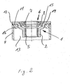
- the annular space 11, in which any welding residues are included, is in Fig. 2 formed by the insertion of a sealing ring 16.
- the design of the sealing and guiding unit shown in FIG. 3 represents a Alternative training to the sealing and guide unit shown in Fig. 2 this design, the stiffening plate 7 is formed in one piece such that it at the same time takes over the function of the support plate 8 according to FIG. 2.
- a pull stop 17 made of elastic material is used instead of inserting a sealing ring 16 according to FIG. 2 to form the annular space 11 3.
- the functions and the assembly of the seal and guide unit according to FIG. 3 correspond the function and assembly of the sealing and guide unit according to Fig. Second
- welds can be carried out as spot or seam welds.
- the welds do not have to be tight, since the sealing of the individual components after outside through inside seals or sealing parts.
Landscapes
- Engineering & Computer Science (AREA)
- General Engineering & Computer Science (AREA)
- Mechanical Engineering (AREA)
- Fluid-Damping Devices (AREA)
- Sealing With Elastic Sealing Lips (AREA)
Abstract
Description
- 1.
- Tragteil
- 2.
- Buchse
- 3.
- Scheibe
- 4.
- Stoßdämpferrohr
- 5.
- Führungsbuchse
- 6.
- Dichtung
- 7.
- Verstärkungsblech
- 8.
- Auflageblech
- 9.
- Bund
- 10.
- Wulst
- 11.
- Ringraum
- 12.
- Schweißnaht
- 13.
- Arbeitsraum
- 14.
- Kragen
- 15.
- Rezess
- 16.
- Dichtring
- 17.
- Zuganschlag
Claims (6)
- Hydraulischer Stoßdämpfer mit einer in ein Stoßdämpferrohr (4) oszillierend einund ausfahrenden Kolbenstange, bei dem die Kolbenstange mittels einer aus Blech hergestellten Dichtungs- und Führungseinheit gegenüber dem Stoßdämpferrohr abgedichtet und geführt wird, wobei die Dichtungs- und Führungseinheit aus einem Tragteil (1) mit einem Führungskragen, der eine Führungsbuchse (5) aufnehmen kann und einer blechverstärkten Dichtung (6) besteht und wobei das Tragteil (1) und/oder das Verstärkungsblech (7) der Dichtung (6) ein- oder mehrteilig ausgebildet ist, dadurch gekennzeichnet, dass wenigstens ein Teil des Tragteils (1) mit wenigstens einem Teil des Verstärkungsbleches (7) form- oder stoffschlüssig verbunden ist.
- Hydraulischer Stoßdämpfer nach Anspruch 1, dadurch gekennzeichnet, dass das Tragteil (1) und das Verstärkungsblech (7) mittels Schweißen, Kleben, Verstemmen und/oder Vernieten miteinander verbunden sind.
- Hydraulischer Stoßdämpfer nach Anspruch 1 oder Anspruch 2, dadurch gekennzeichnet, dass das Verstärkungsblech (7) der Dichtung (6) aus zwei aufeinander liegenden Ringblechen gebildet ist.
- Hydraulischer Stoßdämpfer nach Anspruch 3, dadurch gekennzeichnet, dass das außen liegende Ringblech (Auflageblech 8) sich bis zum Stoßdämpferrohr (4) erstreckt und mit diesem verbunden ist.
- Hydraulischer Stoßdämpfer nach einem oder mehreren der Ansprüche 1 bis 4, dadurch gekennzeichnet, dass bei miteinander verschweißtem Tragteil (1) und Verstärkungsblech (7) die Schweißung von außen erfolgt und die Wurzel der Schweißnaht zum Innenraum des Stoßdämpfers hin mittels eines Einbauteils, vorzugsweise einem Teil der Dichtung (6), abgedichtet ist.
- Hydraulischer Stoßdämpfer nach einem oder mehreren der Ansprüche 1 bis 5, dadurch gekennzeichnet, dass die Dichtungs- und Führungseinheit mit dem Stoßdämpferrohr (4) mittels Schweißen von außen miteinander verbunden ist und die Wurzel der Schweißnaht (12) zum Innenraum des Stoßdämpfers hin mittels eines Einbauteils, vorzugsweise eines Bleches, eines Dichtrings (16) oder eines Zuganschlags (17) aus elastischem Material abgedichtet ist.
Applications Claiming Priority (2)
| Application Number | Priority Date | Filing Date | Title |
|---|---|---|---|
| DE10151023A DE10151023C1 (de) | 2001-10-16 | 2001-10-16 | Hydraulischer Stoßdämpfer |
| DE10151023 | 2001-10-16 |
Publications (3)
| Publication Number | Publication Date |
|---|---|
| EP1302692A2 true EP1302692A2 (de) | 2003-04-16 |
| EP1302692A3 EP1302692A3 (de) | 2004-02-04 |
| EP1302692B1 EP1302692B1 (de) | 2006-05-03 |
Family
ID=7702664
Family Applications (1)
| Application Number | Title | Priority Date | Filing Date |
|---|---|---|---|
| EP02020124A Expired - Lifetime EP1302692B1 (de) | 2001-10-16 | 2002-09-07 | Hydraulischer Stossdämpfer |
Country Status (4)
| Country | Link |
|---|---|
| US (1) | US20030070893A1 (de) |
| EP (1) | EP1302692B1 (de) |
| DE (2) | DE10151023C1 (de) |
| ES (1) | ES2260365T3 (de) |
Cited By (2)
| Publication number | Priority date | Publication date | Assignee | Title |
|---|---|---|---|---|
| US11365781B2 (en) | 2019-10-11 | 2022-06-21 | DRiV Automotive Inc. | Method of manufacturing a monotube shock absorber |
| US11578777B2 (en) | 2019-10-11 | 2023-02-14 | DRiV Automotive Inc. | Sintered metal rod guide assembly for monotube shock absorber |
Families Citing this family (5)
| Publication number | Priority date | Publication date | Assignee | Title |
|---|---|---|---|---|
| DE10332909B4 (de) * | 2003-07-19 | 2007-12-27 | Stabilus Gmbh | Verstellelement |
| US7703587B2 (en) | 2007-01-30 | 2010-04-27 | Zf Friedrichshafen Ag | Rod guide for monotube shock absorbers |
| US8561768B2 (en) * | 2007-08-31 | 2013-10-22 | Honda Motor Co., Ltd. | Vehicle damper and method |
| US10072723B2 (en) * | 2015-04-24 | 2018-09-11 | Beijingwest Industries Co., Ltd. | Closing assembly for a magneto-rheological damper |
| DE102016013638B4 (de) * | 2016-11-16 | 2019-05-02 | Carl Freudenberg Kg | Dichtungsanordnung und deren Verwendung |
Citations (1)
| Publication number | Priority date | Publication date | Assignee | Title |
|---|---|---|---|---|
| DE4030788A1 (de) | 1989-09-29 | 1991-05-23 | Atsugi Unisia Corp | Hydraulischer stossdaempfer |
Family Cites Families (13)
| Publication number | Priority date | Publication date | Assignee | Title |
|---|---|---|---|---|
| US4884665A (en) * | 1985-12-24 | 1989-12-05 | Ford Motor Company | Automotive shock absorber with unitary striker plate and closure cap |
| GB2265436B (en) * | 1989-09-29 | 1994-01-19 | Atsugi Unisia Corp | Hydraulic shock absorber |
| EP0535409B1 (de) * | 1991-10-01 | 1996-02-07 | AUGUST BILSTEIN GMBH & CO. KG | Hydraulischer Schwingungsdämpfer für Kraftfahrzeuge |
| DE4207053C2 (de) * | 1992-03-06 | 1996-03-14 | Bilstein August Gmbh Co Kg | Hydraulischer Schwingungsdämpfer für Kraftfahrzeuge |
| FR2695973B1 (fr) * | 1992-09-18 | 1994-11-18 | Hutchinson | Dispositif de guidage pour tige d'amortisseur. |
| DE4432305A1 (de) * | 1994-09-10 | 1996-03-21 | Bilstein August Gmbh Co Kg | Kolbenstangendichtung |
| DE4436907C2 (de) * | 1994-10-15 | 1997-10-23 | Fichtel & Sachs Ag | Blechkolbenstangenführung für ein Kolbenzylinderaggregat |
| ES2115483B1 (es) * | 1994-12-07 | 1999-02-16 | Sintermetal Sa | Guia del vastago del embolo para amortiguadores hadraulicos. |
| IT1280823B1 (it) * | 1995-03-24 | 1998-02-11 | Rft Spa | Unita di guida e di tenuta per uno stelo, particolarmente per uno stelo di ammortizzatore. |
| JP3753196B2 (ja) * | 1996-04-09 | 2006-03-08 | カヤバ工業株式会社 | ロッドガイドの成形方法 |
| US5706920A (en) * | 1996-08-15 | 1998-01-13 | General Motors Corporation | Monotube damper |
| BR9700537C1 (pt) * | 1997-04-11 | 2000-01-04 | Sabo Ind & Comercio Ltda | Sistema integrado de vedação com guia de haste de amortecedor. |
| DE19819827C1 (de) * | 1998-05-04 | 2000-02-24 | Mannesmann Sachs Ag | Kolbenstangenführung für ein Kolben-Zylinderaggregat |
-
2001
- 2001-10-16 DE DE10151023A patent/DE10151023C1/de not_active Expired - Fee Related
-
2002
- 2002-09-07 EP EP02020124A patent/EP1302692B1/de not_active Expired - Lifetime
- 2002-09-07 DE DE50206636T patent/DE50206636D1/de not_active Expired - Lifetime
- 2002-09-07 ES ES02020124T patent/ES2260365T3/es not_active Expired - Lifetime
- 2002-09-18 US US10/246,643 patent/US20030070893A1/en not_active Abandoned
Patent Citations (1)
| Publication number | Priority date | Publication date | Assignee | Title |
|---|---|---|---|---|
| DE4030788A1 (de) | 1989-09-29 | 1991-05-23 | Atsugi Unisia Corp | Hydraulischer stossdaempfer |
Cited By (2)
| Publication number | Priority date | Publication date | Assignee | Title |
|---|---|---|---|---|
| US11365781B2 (en) | 2019-10-11 | 2022-06-21 | DRiV Automotive Inc. | Method of manufacturing a monotube shock absorber |
| US11578777B2 (en) | 2019-10-11 | 2023-02-14 | DRiV Automotive Inc. | Sintered metal rod guide assembly for monotube shock absorber |
Also Published As
| Publication number | Publication date |
|---|---|
| DE10151023C1 (de) | 2003-02-27 |
| ES2260365T3 (es) | 2006-11-01 |
| US20030070893A1 (en) | 2003-04-17 |
| EP1302692B1 (de) | 2006-05-03 |
| EP1302692A3 (de) | 2004-02-04 |
| DE50206636D1 (de) | 2006-06-08 |
Similar Documents
| Publication | Publication Date | Title |
|---|---|---|
| DE2938927C2 (de) | ||
| DE7718677U1 (de) | Federelement, insbesondere zur elastischen Lagerung von Antriebs- oder sonstigen Aggregaten in Kraftfahrzeugen | |
| DE10122796A1 (de) | Kolben-Zylinderaggregat mit einem Faltbalg | |
| DE10131830B4 (de) | Befestigung eines Topfgasgenerators an einer kegelstumpfförmigen Elastomerfeder | |
| EP1302692B1 (de) | Hydraulischer Stossdämpfer | |
| DE202005001250U1 (de) | Membrane für Membranventil | |
| DE102004018241A1 (de) | Elastisches Fahrerhauslager | |
| DE4322304C1 (de) | Gelenklager, insbesondere für einen Achslenker eines Kraftfahrzeugs | |
| DE69503887T2 (de) | Aufhängungsstreben | |
| DE3202705C2 (de) | Hydropneumatischer Schwingungsdämpfer für Kraftfahrzeuge | |
| DE19513469C1 (de) | Sicherungselement | |
| DE102008041663A1 (de) | Dichtbuchse in einer Scheibenwischvorrichtung | |
| DE102007030641B3 (de) | Höhenverstellbarer Schwingungsdämpfer | |
| DE3637162C2 (de) | Vorderwagen eines Kraftfahrzeuges, insbesondere eines Personenkraftwagens | |
| DE19508851A1 (de) | Federbein, insbesondere für Kraftfahrzeuge | |
| DE10331854B4 (de) | Korrosionsgeschütztes Wischerwellenlager | |
| DE102009022057A1 (de) | Schwingungsdämpfer | |
| DE10329024A1 (de) | Dichtung für einen Drehschieber eines Kühlmittelthermostaten | |
| DE19608771A1 (de) | Führung für ein Kolben-Zylinderaggregat | |
| AT356470B (de) | Vorrichtung zum betaetigen eines absperr- ventiles, eines schiebers od.dgl. fuer rohr- leitungen | |
| DE4240188A1 (de) | Elastische Buchse | |
| WO2019211215A1 (de) | Schwingungsdämpfer mit verstellbarem dämpfventil | |
| DE102005042796B4 (de) | Scheibenbremse für ein Nutzfahrzeug | |
| DE102005060869B4 (de) | Betätigungsanordnung | |
| DE10002091A1 (de) | Schwingungsdämpfendes hydraulisches Stützelement, mit einem derartigen Stützelement ausgerüstetes Fahrwerk und Verfahren zur Herstellung eines derartigen Stützelements |
Legal Events
| Date | Code | Title | Description |
|---|---|---|---|
| PUAI | Public reference made under article 153(3) epc to a published international application that has entered the european phase |
Free format text: ORIGINAL CODE: 0009012 |
|
| AK | Designated contracting states |
Designated state(s): AT BE BG CH CY CZ DE DK EE ES FI FR GB GR IE IT LI LU MC NL PT SE SK TR |
|
| AX | Request for extension of the european patent |
Extension state: AL LT LV MK RO SI |
|
| PUAL | Search report despatched |
Free format text: ORIGINAL CODE: 0009013 |
|
| AK | Designated contracting states |
Kind code of ref document: A3 Designated state(s): AT BE BG CH CY CZ DE DK EE ES FI FR GB GR IE IT LI LU MC NL PT SE SK TR |
|
| AX | Request for extension of the european patent |
Extension state: AL LT LV MK RO SI |
|
| 17P | Request for examination filed |
Effective date: 20040305 |
|
| 17Q | First examination report despatched |
Effective date: 20040723 |
|
| AKX | Designation fees paid |
Designated state(s): DE ES FR GB IT |
|
| GRAP | Despatch of communication of intention to grant a patent |
Free format text: ORIGINAL CODE: EPIDOSNIGR1 |
|
| GRAS | Grant fee paid |
Free format text: ORIGINAL CODE: EPIDOSNIGR3 |
|
| GRAA | (expected) grant |
Free format text: ORIGINAL CODE: 0009210 |
|
| RAP1 | Party data changed (applicant data changed or rights of an application transferred) |
Owner name: THYSSENKRUPP BILSTEIN SUSPENSION GMBH |
|
| AK | Designated contracting states |
Kind code of ref document: B1 Designated state(s): DE ES FR GB IT |
|
| REG | Reference to a national code |
Ref country code: GB Ref legal event code: FG4D Free format text: NOT ENGLISH |
|
| GBT | Gb: translation of ep patent filed (gb section 77(6)(a)/1977) |
Effective date: 20060504 |
|
| REF | Corresponds to: |
Ref document number: 50206636 Country of ref document: DE Date of ref document: 20060608 Kind code of ref document: P |
|
| ET | Fr: translation filed | ||
| REG | Reference to a national code |
Ref country code: ES Ref legal event code: FG2A Ref document number: 2260365 Country of ref document: ES Kind code of ref document: T3 |
|
| PLBE | No opposition filed within time limit |
Free format text: ORIGINAL CODE: 0009261 |
|
| STAA | Information on the status of an ep patent application or granted ep patent |
Free format text: STATUS: NO OPPOSITION FILED WITHIN TIME LIMIT |
|
| 26N | No opposition filed |
Effective date: 20070206 |
|
| PGFP | Annual fee paid to national office [announced via postgrant information from national office to epo] |
Ref country code: ES Payment date: 20100924 Year of fee payment: 9 |
|
| PGFP | Annual fee paid to national office [announced via postgrant information from national office to epo] |
Ref country code: FR Payment date: 20101005 Year of fee payment: 9 Ref country code: IT Payment date: 20100923 Year of fee payment: 9 |
|
| PGFP | Annual fee paid to national office [announced via postgrant information from national office to epo] |
Ref country code: GB Payment date: 20100921 Year of fee payment: 9 |
|
| PGFP | Annual fee paid to national office [announced via postgrant information from national office to epo] |
Ref country code: DE Payment date: 20100922 Year of fee payment: 9 |
|
| GBPC | Gb: european patent ceased through non-payment of renewal fee |
Effective date: 20110907 |
|
| PG25 | Lapsed in a contracting state [announced via postgrant information from national office to epo] |
Ref country code: IT Free format text: LAPSE BECAUSE OF NON-PAYMENT OF DUE FEES Effective date: 20110907 |
|
| REG | Reference to a national code |
Ref country code: FR Ref legal event code: ST Effective date: 20120531 |
|
| REG | Reference to a national code |
Ref country code: DE Ref legal event code: R119 Ref document number: 50206636 Country of ref document: DE Effective date: 20120403 |
|
| PG25 | Lapsed in a contracting state [announced via postgrant information from national office to epo] |
Ref country code: DE Free format text: LAPSE BECAUSE OF NON-PAYMENT OF DUE FEES Effective date: 20120403 |
|
| PG25 | Lapsed in a contracting state [announced via postgrant information from national office to epo] |
Ref country code: FR Free format text: LAPSE BECAUSE OF NON-PAYMENT OF DUE FEES Effective date: 20110930 Ref country code: GB Free format text: LAPSE BECAUSE OF NON-PAYMENT OF DUE FEES Effective date: 20110907 |
|
| REG | Reference to a national code |
Ref country code: ES Ref legal event code: FD2A Effective date: 20130417 |
|
| PG25 | Lapsed in a contracting state [announced via postgrant information from national office to epo] |
Ref country code: ES Free format text: LAPSE BECAUSE OF NON-PAYMENT OF DUE FEES Effective date: 20110908 |