EP1302833A2 - Ensemble de pédale de frein compacte avec bras de capteur électrique pivotant sur un axe espacé de l'axe de pédale - Google Patents
Ensemble de pédale de frein compacte avec bras de capteur électrique pivotant sur un axe espacé de l'axe de pédale Download PDFInfo
- Publication number
- EP1302833A2 EP1302833A2 EP02079118A EP02079118A EP1302833A2 EP 1302833 A2 EP1302833 A2 EP 1302833A2 EP 02079118 A EP02079118 A EP 02079118A EP 02079118 A EP02079118 A EP 02079118A EP 1302833 A2 EP1302833 A2 EP 1302833A2
- Authority
- EP
- European Patent Office
- Prior art keywords
- sensor
- pedal
- assembly
- housing
- axis
- Prior art date
- Legal status (The legal status is an assumption and is not a legal conclusion. Google has not performed a legal analysis and makes no representation as to the accuracy of the status listed.)
- Withdrawn
Links
- 230000007246 mechanism Effects 0.000 claims abstract description 13
- 230000004044 response Effects 0.000 claims description 8
- 238000005192 partition Methods 0.000 claims description 5
- 230000035945 sensitivity Effects 0.000 description 2
- 230000009471 action Effects 0.000 description 1
- 230000000712 assembly Effects 0.000 description 1
- 238000000429 assembly Methods 0.000 description 1
- 230000004048 modification Effects 0.000 description 1
- 238000012986 modification Methods 0.000 description 1
- 238000004806 packaging method and process Methods 0.000 description 1
Images


Classifications
-
- G—PHYSICS
- G05—CONTROLLING; REGULATING
- G05G—CONTROL DEVICES OR SYSTEMS INSOFAR AS CHARACTERISED BY MECHANICAL FEATURES ONLY
- G05G1/00—Controlling members, e.g. knobs or handles; Assemblies or arrangements thereof; Indicating position of controlling members
- G05G1/30—Controlling members actuated by foot
- G05G1/38—Controlling members actuated by foot comprising means to continuously detect pedal position
-
- G—PHYSICS
- G05—CONTROLLING; REGULATING
- G05G—CONTROL DEVICES OR SYSTEMS INSOFAR AS CHARACTERISED BY MECHANICAL FEATURES ONLY
- G05G1/00—Controlling members, e.g. knobs or handles; Assemblies or arrangements thereof; Indicating position of controlling members
- G05G1/30—Controlling members actuated by foot
- G05G1/46—Means, e.g. links, for connecting the pedal to the controlled unit
-
- G—PHYSICS
- G05—CONTROLLING; REGULATING
- G05G—CONTROL DEVICES OR SYSTEMS INSOFAR AS CHARACTERISED BY MECHANICAL FEATURES ONLY
- G05G5/00—Means for preventing, limiting or returning the movements of parts of a control mechanism, e.g. locking controlling member
- G05G5/03—Means for enhancing the operator's awareness of arrival of the controlling member at a command or datum position; Providing feel, e.g. means for creating a counterforce
-
- Y—GENERAL TAGGING OF NEW TECHNOLOGICAL DEVELOPMENTS; GENERAL TAGGING OF CROSS-SECTIONAL TECHNOLOGIES SPANNING OVER SEVERAL SECTIONS OF THE IPC; TECHNICAL SUBJECTS COVERED BY FORMER USPC CROSS-REFERENCE ART COLLECTIONS [XRACs] AND DIGESTS
- Y10—TECHNICAL SUBJECTS COVERED BY FORMER USPC
- Y10T—TECHNICAL SUBJECTS COVERED BY FORMER US CLASSIFICATION
- Y10T74/00—Machine element or mechanism
- Y10T74/20—Control lever and linkage systems
- Y10T74/20528—Foot operated
- Y10T74/20534—Accelerator
-
- Y—GENERAL TAGGING OF NEW TECHNOLOGICAL DEVELOPMENTS; GENERAL TAGGING OF CROSS-SECTIONAL TECHNOLOGIES SPANNING OVER SEVERAL SECTIONS OF THE IPC; TECHNICAL SUBJECTS COVERED BY FORMER USPC CROSS-REFERENCE ART COLLECTIONS [XRACs] AND DIGESTS
- Y10—TECHNICAL SUBJECTS COVERED BY FORMER USPC
- Y10T—TECHNICAL SUBJECTS COVERED BY FORMER US CLASSIFICATION
- Y10T74/00—Machine element or mechanism
- Y10T74/20—Control lever and linkage systems
- Y10T74/20528—Foot operated
- Y10T74/2054—Signal
Definitions
- the subject invention relates to a pedal assembly with a sensor that generates an electric signal for controlling a vehicle system.
- Pedal assemblies for controlling the throttle, clutch and braking systems in automotive vehicles have recently replaced mechanical linkage mechanisms with electrical sensors to generate electrical signals indicative of the degree of movement of the pedal to control the vehicle system. Besides cost and performance criteria, it is essential that the assembly occupy a minimum of space, as space within a vehicle is limited and is in demand for various uses.
- the pedal lever rotates a sensor arm that supports sensor members and circular sensor bands are supported by the housing to co-act with the sensor members to produce and electrical signal.
- the sensor arm extends radially from the pivot axis of the pedal and in order to obtain the desired sensitivity, the movement of the sensor members over the bands must be maximized or be at least a predetermined amount.
- the radial extent of the sensor arm must be sufficient to obtain a sufficiently long enough arc of sensor band to attain the requisite sensitivity.
- the demands for space are so critical that it is desirable to reduce the space between the axis of rotation of the pedal arm the sensor band or bands, whether the bands be straight or arcuate.
- the subject assembly provides a compact pedal assembly for electronically controlling a vehicle.
- the assembly comprises a housing, a pedal lever supported by the housing for pivotal movement about a pedal axis, and a sensor arm movably supported by the housing.
- the housing supports at least one sensing band and at least one sensor member is supported by the sensor arm for movement with the sensor arm to co-act with the sensing band.
- the assembly is characterized by a mechanism of at least two elements movable relative to one another and interconnecting the pedal lever and the sensor arm for moving the sensor arm in response to movement of the pedal lever.
- the operative space of the pedal lever and the sensor arm can be reduced to provide more compact packaging.
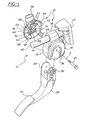
- Figure 1 is an exploded-perspective view from the brake cover side of the preferred embodiment
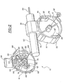
- Figure 2 is an exploded perspective view of the housing and the sensor cover of the preferred embodiment
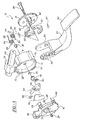
- Figure 3 is an exploded perspective view of the housing and the brake cover of the preferred embodiment
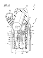
- Figure 4 is an exploded-perspective view from the sensor cover side of the preferred embodiment
- Figure 5 is a perspective view from the brake cover side and partially cut away and in cross section of the preferred embodiment.
- Figure 6 is a perspective view from the front and partially cut away and in cross section of the preferred embodiment.
- a pedal assembly for electronically controlling a vehicle is generally shown at 10 .
- the assembly 10 includes a housing, generally shown at 12 , having opposite sides.
- the housing 12 includes a central drum section 14 extending between open first and second ends.
- a sensor cover 16 closes the first end to define one of the housing sides and a brake cover 18 closes the second end to define the other housing side.
- a pedal lever 20 is supported by the housing 12 for pivotal movement about a pedal axis (A) extending between the sides, i.e., between the covers 16 and 18 .
- the central section 14 of the housing 12 includes a center partition 22 and a shaft 24 extends through the covers 16 and 18 and the partition 22.
- the shaft 24 comprises a bolt and nut 26 that also support the o-ring seals 28 and 30 and the bushing 32.
- the shaft may be a press fit pin with snap-in bushings replacing the nut 26 and bushing 32 .
- the pedal lever 20 has a forked end with two tongs 34 and the covers 16 and 18 of the housing 12 are disposed between the tongs 34 with the tongs 34 secured to the shaft 24 and the brake cover 18 for rotation therewith.
- the brake cover 18 includes a rib 36 to define a stop or mechanical connection engaging one tong of the pedal lever 20 so that the brake cover 18 rotates relative to the central section 14 of the remainder of the housing 12.
- the central section 14 of the housing 12 includes a carrier section 38 slidably supported on a guide rod 40 for adjusting the operative positions of the pedal assembly 10 for accommodating vehicle operators having different leg lengths.
- the rod 40 is supported by a bracket 42 adapted to be mounted on a vehicle structure and the guide section 38 is moved rectilinearly along the guide rod 40 between various adjusted positions by a screw 44, as is well known in the art and exemplified by the disclosure in U.S. Patent 5,964,125.
- the sensor cover 16 of the housing 12 movably supports a sensor arm 46. More specifically, the sensor arm 46 is pivotally supported by the sensor cover 16 for pivotal movement about a sensor axis defined by a pin 48 extending integrally from the sensor cover 16.
- the sensor axis of the pin 48 is spaced from the pedal axis (A) and disposed on one diametrical side of the pedal axis (A) with the sensor arm 46 extending to the opposite diametrical side of the pedal axis (A).
- a plurality of the sensing bands 50 are supported on the sensor cover 16 of the housing 12 via a plate 52 and the bands 50 disposed arcuately (circular segments) at different radial distances from the sensor axis of the pin 48.
- the sensor bands 50 are in electrical contact with electrical pins 54 which are in electrical communication with the electrical connector 56 that connects to the vehicle system.
- a plurality of sensor members 58 are supported on the sensor arm 46 at the different radial distances form the sensor axis 48 and each of the sensor members 58 is paired with one of the sensor bands 50.
- a coil spring defines a biasing device 60 for applying a biasing force to the sensor arm 46 for urging the sensor arm 46 to rotate about the sensor axis of the pin 48 .
- the spring 60 reacts between the sensor arm 46 and an abutment pin 62 extending from the sensor cover 16 .
- a stop 64 to limit rotary movement of the sensor arm 46 about the sensor axis 48 in response to the biasing force applied by the biasing device 60.
- the sensor arm 46 includes an opening 66 and the pedal axis (A) is disposed in the opening 66 . Accordingly, the sensor bands 50 and the sensor members 58 are disposed on the opposite diametrical side of the pedal axis (A) from the sensor axis 48.
- the sensor cover 16 is prevented from rotating relative to the central section 14 of the housing 12 by tabs 68 that snap into pockets 70 in the central section 14.
- the sensor cover 16 includes an external ridge 72 that accommodates pivotal movement of the pedal lever 20 relative to the sensor cover 16 .
- the assembly is characterized by a mechanism of at least two elements movable relative to one another and interconnecting the pedal lever 20 and the sensor arm 46 for moving the sensor arm 46 in response to movement of the pedal lever 20. More specifically, one of the elements comprises a gear sector or sensor gear 74 and the other element comprises a pedal gear 76 rotatable by the pedal lever 20 through the shaft 24 about the pedal axis (A).
- the sensor gear 74 is disposed in the opening 66 of the sensor arm 46 and is in meshing engagement with the pedal gear 76 whereby the sensor gear 74 is rotatable by the pedal gear 76 for rotating the sensor arm 46 about the sensor axis 48.
- the pedal axis (A) is disposed in the opening 66 in the sensor arm 46 to accommodate movement of the sensor arm 46 and the sensor member 58 radially through the pedal axis (A), i.e., the sensor members 58 are on a radial extending from the sensor axis 48 and which moves in an arc back and forth to either side of the pedal axis (A).
- the pedal gear may drive a rack rectilinearly instead of in an arc.
- the requisite degree of movement of the sensor members 58 may be attained while minimizing the distance occupied between the pedal axis (A) and the sensor bands 50.
- the assembly 10 also includes a braking mechanism supported by the brake cover 18 for providing resistance to movement of the pedal lever 20 about the pedal axis (A).
- the assembly is also characterized by the sensor arm 46 and the braking mechanism being axially spaced from one another along the pedal axis (A) and disposed in radially overlapping relationship to one another.
- Such a combination also provides a compact pedal assembly 10 .
- the central section 14 of the housing 12 includes a inner cylindrical surface 78 a pair of brake shoes 80 are movably supported by the brake cover 18 of the housing 12 for movement radially outwardly into engagement with the cylindrical surface 78 for providing resistance to movement of the pedal lever 20.
- a pair of posts 82 extend axially from the inside of the brake cover 18 of the housing 12 and each of the brake shoes 80 extends arcuately from a pivot end pivotally supported by one of the posts 82 to a distal end.
- a brake actuator comprising a biasing coil spring 84 interconnecting each brake shoe 80 and the housing 12 for moving the brake shoe 80 into engagement with the inner cylindrical surface 78 in response to pivotal movement of the pedal lever 20 in a first direction, that is, as force is applied to the pedal pad 90 supported on the lower end of the pedal lever 20 .
- Each coil spring 84 has a central coil disposed about one of the posts 82 with a first end 86 extending from the coil and engaging the distal end of the adjacent brake shoe 80 supported by that same post 82 and a second end 88 extending from the coil and engaging a shoulder 92 extending from the inner cylindrical surface 78 of the central section 14 of the housing 12 .
- Each of the brake shoes 80 includes a brake pad 94 for frictional engaging the inner cylindrical surface 78.
- the brake cover 18 is rotatable with the pedal lever 20 relative to the central section 14 of the housing 12 as it rotates in response to an operator force applied to the pedal pad 90 , the shaft 24 rotates to rotate the pedal gear 76.
- the pedal gear 76 rotates the sensor gear 74 to, in turn, rotate or pivot the sensor arm 46 about the sensor axis 48 .
- the sensor members 58 move along the sensor bands 50 to generate an electrical signal that is transmitted to the vehicle control system.
- the brake cover 18 rotates with the pedal lever 20 to uncoil the coil springs 84 as they react with the shoulders 92 of the central section 14 of the housing 12.
- the uncoiling action of the springs 84 cause the brake shoes 80 to pivot radially outward about the respective posts 82 so that the brake pads 94 frictionally engage the interior surface 78 of the central section 14 to thereby provide a resistance or hysteresis to movement of the pedal lever 20.
- pedal assembly 10 rod 40 tabs 68 housing 12 bracket 42 pockets 70 central section 14 screw 44 ridge 72 sensor cover 16 sensor arm 46 sensor gear 74 brake cover 18 pin 48 pedal gear 76 pedal lever 20 sensing bands 50 cylindrical surface 78 partition 22 plate 52 brake shoes 80 shaft 24 electrical pins 54 posts 82 nut 26 electrical connector 56 coiled springs 84 o-ring seals 28 and 30 sensor members 58 first end 86 bushing 32 biasing device 60 second end 88 tongs 34 abutment pin 62 pedal pad 90 rib 36 stop 64 shoulders 92 carrier section 38 opening 66 brake pad 94
Landscapes
- Physics & Mathematics (AREA)
- General Physics & Mathematics (AREA)
- Engineering & Computer Science (AREA)
- Automation & Control Theory (AREA)
- Braking Elements And Transmission Devices (AREA)
- Mechanical Control Devices (AREA)
- Braking Arrangements (AREA)
Applications Claiming Priority (2)
| Application Number | Priority Date | Filing Date | Title |
|---|---|---|---|
| US974152 | 1992-11-10 | ||
| US09/974,152 US6725741B2 (en) | 2001-10-09 | 2001-10-09 | Compact pedal assembly with electrical sensor arm pivotal about axis spaced from pedal axis |
Publications (2)
| Publication Number | Publication Date |
|---|---|
| EP1302833A2 true EP1302833A2 (fr) | 2003-04-16 |
| EP1302833A3 EP1302833A3 (fr) | 2003-09-03 |
Family
ID=25521658
Family Applications (1)
| Application Number | Title | Priority Date | Filing Date |
|---|---|---|---|
| EP02079118A Withdrawn EP1302833A3 (fr) | 2001-10-09 | 2002-10-04 | Ensemble de pédale de frein compacte avec bras de capteur électrique pivotant sur un axe espacé de l'axe de pédale |
Country Status (6)
| Country | Link |
|---|---|
| US (1) | US6725741B2 (fr) |
| EP (1) | EP1302833A3 (fr) |
| JP (1) | JP2003216258A (fr) |
| KR (1) | KR20030047708A (fr) |
| CA (1) | CA2406813A1 (fr) |
| MX (1) | MXPA02009990A (fr) |
Cited By (4)
| Publication number | Priority date | Publication date | Assignee | Title |
|---|---|---|---|---|
| KR20030047708A (ko) * | 2001-10-09 | 2003-06-18 | 텔레플렉스 인코포레이티드 | 페달축선으로부터 이격된 축선을 중심으로 피벗동작가능한 전기센서아암을 구비한 콤팩트한 페달조립체 |
| EP1936470A1 (fr) * | 2006-12-20 | 2008-06-25 | Wabash Technologies, Inc. | Ensemble de pédale intégrée ayant un mécanisme d'hystérèse |
| WO2010104209A1 (fr) * | 2009-03-11 | 2010-09-16 | Denso Corporation | Appareil à pédale |
| FR3034885A1 (fr) * | 2015-04-10 | 2016-10-14 | Peugeot Citroen Automobiles Sa | Pedale d'embrayage avec dispositif de restitution d'effort, pour un embrayage equipe d'un actionneur electrique |
Families Citing this family (23)
| Publication number | Priority date | Publication date | Assignee | Title |
|---|---|---|---|---|
| DE10105265B4 (de) * | 2001-02-02 | 2007-01-04 | ZF Lemförder Metallwaren AG | Rückstellvorrichtung für Pedale eines Kraftfahrzeuges |
| WO2004007929A2 (fr) * | 2002-07-17 | 2004-01-22 | Ksr International Co. | Commande d'accelerateur electronique comprenant un dispositif d'hysteresis |
| US6860170B2 (en) * | 2002-09-09 | 2005-03-01 | Dura Global Technologies, Inc. | Electronic throttle control hysteresis mechanism |
| EP1627268B1 (fr) * | 2003-05-29 | 2008-05-14 | CTS Corporation | Pedale d'accelerateur pour vehicule a moteur |
| US20050039564A1 (en) * | 2003-08-20 | 2005-02-24 | Jiyuan Ouyang | Pedal assembly for a vehicle including a non-contact position sensor |
| US20060117902A1 (en) * | 2004-11-29 | 2006-06-08 | Tom Martin | Pedal assembly with an integrated non-contact rotational position sensor |
| JP4831472B2 (ja) * | 2006-02-09 | 2011-12-07 | 株式会社デンソー | ペダルモジュール |
| US20070234842A1 (en) * | 2006-04-07 | 2007-10-11 | Ksr International Co. | Electronic throttle control with hysteresis and kickdown |
| US7351901B2 (en) * | 2006-05-02 | 2008-04-01 | K.H.S. Musical Instrument Co., Ltd. | Bearing device for a pedal assembly |
| US20080079207A1 (en) * | 2006-09-28 | 2008-04-03 | Williams Controils Industries, Inc. | Methods and apparatus for a lever control |
| US20090160633A1 (en) * | 2007-12-21 | 2009-06-25 | Textron Inc. | Brake light system for utility vehicle |
| JP4591799B2 (ja) * | 2008-03-19 | 2010-12-01 | 株式会社デンソー | アクセル装置 |
| US8534157B2 (en) | 2010-02-17 | 2013-09-17 | Ksr Technologies Co. | Electronic throttle control pedal assembly with hysteresis |
| US20110277583A1 (en) * | 2010-05-12 | 2011-11-17 | Ksr Technologies Co. | Compact fly-by-wire pedal assembly |
| EP2652571A1 (fr) | 2010-12-16 | 2013-10-23 | Kongsberg Power Products Systems I, Inc | Procédé d'assemblage d'un ensemble pédale |
| FR2995101B1 (fr) * | 2012-08-31 | 2014-08-29 | Coutier Moulage Gen Ind | Pedalier allege renforce vis-a-vis des efforts de commande decales |
| US9360882B2 (en) * | 2012-10-02 | 2016-06-07 | Cts Corporation | Vehicle pedal with index assembly for contacting sensor |
| US9632525B2 (en) | 2013-09-27 | 2017-04-25 | Cts Corporation | Shaftless vehicle pedal with contacting position sensor |
| US10175712B2 (en) * | 2015-05-17 | 2019-01-08 | Cts Corporation | Compact vehicle pedal |
| DE102017207417B4 (de) * | 2016-06-03 | 2022-08-11 | Ford Global Technologies, Llc | Vorrichtung zur Kraftsimulation an einem Betätigungselement eines Fahrzeugs und elektrisch betätigtes Kupplungssystem |
| WO2018039122A1 (fr) | 2016-08-24 | 2018-03-01 | Cts Corporation | Rotor d'une pédale de véhicule pourvue d'un capteur de contact |
| CN109819651B (zh) * | 2017-09-18 | 2023-03-24 | 麦格纳国际公司 | 紧凑式动力踏板 |
| JP7354066B2 (ja) * | 2020-08-05 | 2023-10-02 | 豊田鉄工株式会社 | 車両用操作ペダル装置における操作量センサ取付構造 |
Citations (2)
| Publication number | Priority date | Publication date | Assignee | Title |
|---|---|---|---|---|
| US5964125A (en) | 1995-08-09 | 1999-10-12 | Teleflex Incorporated | Electric adjustable pedal assembly |
| US6220222B1 (en) | 1999-05-18 | 2001-04-24 | Teleflex Incorporated | Electronic control assembly for a pedal |
Family Cites Families (32)
| Publication number | Priority date | Publication date | Assignee | Title |
|---|---|---|---|---|
| US2111755A (en) * | 1936-12-29 | 1938-03-22 | Otis F Compton | Brake |
| US4869220A (en) * | 1988-02-18 | 1989-09-26 | Siemens-Bendix Automotive Electronics L.P. | Accelerator control apparatus |
| US4958607A (en) | 1989-04-18 | 1990-09-25 | Williams Controls, Inc. | Foot pedal arrangement for electronic throttle control of truck engines |
| USRE34302E (en) * | 1989-09-18 | 1993-07-06 | Siemens Automotive L.P. | Accelerating pedal for electronic throttle actuation system |
| US5233882A (en) * | 1990-07-12 | 1993-08-10 | General Motors Corporation | Remote control lever module |
| US5241936A (en) * | 1991-09-09 | 1993-09-07 | Williams Controls, Inc. | Foot pedal arrangement for electronic throttle control of truck engines |
| FR2696397B1 (fr) | 1992-10-07 | 1994-12-02 | Bendix Europ Services Tech | Dispositif de pédale pour véhicule automobile notamment pour système de freinage. |
| US5529296A (en) | 1992-11-05 | 1996-06-25 | Nippondenso Co., Ltd. | Pedal return device having improved hysteresis characteristics |
| US5385068A (en) * | 1992-12-18 | 1995-01-31 | Cts Corporation | Electronic accelerator pedal assembly with pedal force sensor |
| US5408899A (en) | 1993-06-14 | 1995-04-25 | Brecom Subsidiary Corporation No. 1 | Foot pedal devices for controlling engines |
| DE4407005C1 (de) | 1994-03-03 | 1995-03-09 | Hella Kg Hueck & Co | Fahrpedaleinrichtung |
| US5768946A (en) * | 1994-10-11 | 1998-06-23 | Cts Corporation | Pedal with integrated position sensor |
| DE19511716C1 (de) | 1995-03-30 | 1996-04-04 | Porsche Ag | Verbindungseinrichtung |
| DE19514541C2 (de) | 1995-04-20 | 1998-01-15 | Daimler Benz Ag | Gaspedal mit Reibkörper |
| US6003404A (en) | 1995-05-10 | 1999-12-21 | Vdo Adolf Schindling Ag | Accelerator pedal assembly for controlling the power of an internal combustion engine |
| DE19521821C1 (de) | 1995-06-16 | 1996-12-12 | Hella Kg Hueck & Co | Fahrpedaleinrichtung |
| DE19536699A1 (de) | 1995-09-30 | 1997-04-03 | Bosch Gmbh Robert | Fahrpedalmodul |
| DE19536606A1 (de) | 1995-09-30 | 1997-04-03 | Bosch Gmbh Robert | Fahrpedalmodul |
| DE19612830C1 (de) | 1996-03-30 | 1997-07-24 | Hella Kg Hueck & Co | Fahrpedalgeber |
| DE29611890U1 (de) | 1996-07-09 | 1996-09-12 | Hella KG Hueck & Co., 59557 Lippstadt | Drehsensor |
| DE19627556A1 (de) | 1996-07-09 | 1998-01-15 | Hella Kg Hueck & Co | Widerstandsdrehsensor |
| US5865067A (en) | 1996-11-06 | 1999-02-02 | Knapp; Richard C. | Pedal mounting structure and method of installing a pedal in an automotive vehicle |
| US6164155A (en) * | 1998-11-13 | 2000-12-26 | Honeywell Commerical Vehicle Systems Co. | Electronic treadle gear design |
| US6401566B1 (en) * | 1999-05-13 | 2002-06-11 | Williams Controls Industries, Inc. | Control lever having eccentrically mounted return spring |
| DE19924410A1 (de) | 1999-05-27 | 2000-11-30 | Hella Kg Hueck & Co | Fahrpedalgeber |
| US6147590A (en) * | 1999-09-10 | 2000-11-14 | Mikolcic; Allen | Electronic treadle linkage assembly |
| EP1224387A1 (fr) * | 1999-10-29 | 2002-07-24 | William C. Staker | Pedale de commande de vitesse electronique, dispositif capteur de position et procede d'assemblage |
| DE69923320T2 (de) * | 1999-11-04 | 2006-04-06 | Cts Corp., Elkhart | Elektronisches Fahrpedal mit einem Kickdown-System |
| US6622589B1 (en) * | 1999-11-19 | 2003-09-23 | Aptek Williams, Inc. | Manual control apparatus |
| JP3436512B2 (ja) * | 1999-12-28 | 2003-08-11 | 株式会社デンソー | アクセル装置 |
| US6330838B1 (en) * | 2000-05-11 | 2001-12-18 | Teleflex Incorporated | Pedal assembly with non-contact pedal position sensor for generating a control signal |
| US6725741B2 (en) * | 2001-10-09 | 2004-04-27 | Teleflex Incorporated | Compact pedal assembly with electrical sensor arm pivotal about axis spaced from pedal axis |
-
2001
- 2001-10-09 US US09/974,152 patent/US6725741B2/en not_active Expired - Fee Related
-
2002
- 2002-10-04 EP EP02079118A patent/EP1302833A3/fr not_active Withdrawn
- 2002-10-08 CA CA002406813A patent/CA2406813A1/fr not_active Abandoned
- 2002-10-09 JP JP2002295834A patent/JP2003216258A/ja active Pending
- 2002-10-09 KR KR1020020061516A patent/KR20030047708A/ko not_active Ceased
- 2002-10-10 MX MXPA02009990A patent/MXPA02009990A/es unknown
Patent Citations (2)
| Publication number | Priority date | Publication date | Assignee | Title |
|---|---|---|---|---|
| US5964125A (en) | 1995-08-09 | 1999-10-12 | Teleflex Incorporated | Electric adjustable pedal assembly |
| US6220222B1 (en) | 1999-05-18 | 2001-04-24 | Teleflex Incorporated | Electronic control assembly for a pedal |
Cited By (5)
| Publication number | Priority date | Publication date | Assignee | Title |
|---|---|---|---|---|
| KR20030047708A (ko) * | 2001-10-09 | 2003-06-18 | 텔레플렉스 인코포레이티드 | 페달축선으로부터 이격된 축선을 중심으로 피벗동작가능한 전기센서아암을 구비한 콤팩트한 페달조립체 |
| EP1936470A1 (fr) * | 2006-12-20 | 2008-06-25 | Wabash Technologies, Inc. | Ensemble de pédale intégrée ayant un mécanisme d'hystérèse |
| US8011270B2 (en) | 2006-12-20 | 2011-09-06 | Wabash Technologies, Inc. | Integrated pedal assembly having a hysteresis mechanism |
| WO2010104209A1 (fr) * | 2009-03-11 | 2010-09-16 | Denso Corporation | Appareil à pédale |
| FR3034885A1 (fr) * | 2015-04-10 | 2016-10-14 | Peugeot Citroen Automobiles Sa | Pedale d'embrayage avec dispositif de restitution d'effort, pour un embrayage equipe d'un actionneur electrique |
Also Published As
| Publication number | Publication date |
|---|---|
| MXPA02009990A (es) | 2004-10-15 |
| EP1302833A3 (fr) | 2003-09-03 |
| US20030070503A1 (en) | 2003-04-17 |
| KR20030047708A (ko) | 2003-06-18 |
| JP2003216258A (ja) | 2003-07-31 |
| CA2406813A1 (fr) | 2003-04-09 |
| US6725741B2 (en) | 2004-04-27 |
Similar Documents
| Publication | Publication Date | Title |
|---|---|---|
| US6725741B2 (en) | Compact pedal assembly with electrical sensor arm pivotal about axis spaced from pedal axis | |
| US6718845B2 (en) | Pedal assembly with radially overlying sensor and hysteresis | |
| US6003404A (en) | Accelerator pedal assembly for controlling the power of an internal combustion engine | |
| US7404342B2 (en) | Accelerator pedal for motorized vehicle | |
| US7216563B2 (en) | Electronic throttle control with hysteresis device | |
| US5416295A (en) | Combined pedal force switch and position sensor | |
| US5063811A (en) | Accelerator pedal assembly | |
| CN113302572A (zh) | 用于车辆的踏板仿真器 | |
| US20060185469A1 (en) | Pedal for motorized vehicle | |
| EP0990782B1 (fr) | Mecanisme de pedale d'accelerateur pour vehicule | |
| US6276229B1 (en) | Gas-pedal module | |
| EP0849108A2 (fr) | Dispositif de contrÔle électrique avec indicateur tactile unidirectionel | |
| EP1230584A2 (fr) | Dispositif de commande manuel | |
| MXPA00008025A (es) | Tronillo y vastago paralelos de pedal regulable. | |
| JP2763581B2 (ja) | シフトレバー装置 | |
| WO2011141802A1 (fr) | Ensemble pédale compact à commande électrique | |
| US6279883B1 (en) | Bearing module for an actuating element | |
| KR100614524B1 (ko) | 가속페달의 반력 조절 장치 | |
| GB2300280A (en) | Transmission device for controlling an ic engine | |
| JP3609986B2 (ja) | アクセルペダル装置 | |
| JP2009012576A (ja) | 電動パーキングブレーキ装置 | |
| WO1999004149A1 (fr) | Organe d'actionnement de vanne papillon | |
| JPH08105331A (ja) | 出力制御装置 | |
| CA2593677C (fr) | Dispositif de commande manuel | |
| JPH0531523Y2 (fr) |
Legal Events
| Date | Code | Title | Description |
|---|---|---|---|
| PUAI | Public reference made under article 153(3) epc to a published international application that has entered the european phase |
Free format text: ORIGINAL CODE: 0009012 |
|
| AK | Designated contracting states |
Designated state(s): AT BE BG CH CY CZ DE DK EE ES FI FR GB GR IE IT LI LU MC NL PT SE SK TR |
|
| AX | Request for extension of the european patent |
Extension state: AL LT LV MK RO SI |
|
| PUAL | Search report despatched |
Free format text: ORIGINAL CODE: 0009013 |
|
| AK | Designated contracting states |
Kind code of ref document: A3 Designated state(s): AT BE BG CH CY CZ DE DK EE ES FI FR GB GR IE IT LI LU MC NL PT SE SK TR |
|
| AX | Request for extension of the european patent |
Extension state: AL LT LV MK RO SI |
|
| RIC1 | Information provided on ipc code assigned before grant |
Ipc: 7G 05G 7/10 B Ipc: 7G 05G 1/14 B Ipc: 7F 02D 11/02 A |
|
| 17P | Request for examination filed |
Effective date: 20040301 |
|
| AKX | Designation fees paid |
Designated state(s): DE ES FR GB IT |
|
| 17Q | First examination report despatched |
Effective date: 20040427 |
|
| STAA | Information on the status of an ep patent application or granted ep patent |
Free format text: STATUS: THE APPLICATION IS DEEMED TO BE WITHDRAWN |
|
| 18D | Application deemed to be withdrawn |
Effective date: 20040908 |