EP1303228B1 - Flexibles chirurgisches instrument - Google Patents
Flexibles chirurgisches instrument Download PDFInfo
- Publication number
- EP1303228B1 EP1303228B1 EP02709537A EP02709537A EP1303228B1 EP 1303228 B1 EP1303228 B1 EP 1303228B1 EP 02709537 A EP02709537 A EP 02709537A EP 02709537 A EP02709537 A EP 02709537A EP 1303228 B1 EP1303228 B1 EP 1303228B1
- Authority
- EP
- European Patent Office
- Prior art keywords
- shaft
- flexible
- catheter
- tool
- drive unit
- Prior art date
- Legal status (The legal status is an assumption and is not a legal conclusion. Google has not performed a legal analysis and makes no representation as to the accuracy of the status listed.)
- Expired - Lifetime
Links
- 230000007246 mechanism Effects 0.000 claims description 119
- 238000000034 method Methods 0.000 claims description 100
- 230000033001 locomotion Effects 0.000 claims description 61
- 238000005452 bending Methods 0.000 claims description 35
- 230000003278 mimic effect Effects 0.000 claims description 2
- 238000012546 transfer Methods 0.000 claims description 2
- 230000003362 replicative effect Effects 0.000 claims 1
- 210000004115 mitral valve Anatomy 0.000 description 84
- 239000000835 fiber Substances 0.000 description 45
- 210000003709 heart valve Anatomy 0.000 description 28
- 230000008439 repair process Effects 0.000 description 27
- 230000001276 controlling effect Effects 0.000 description 22
- 239000000463 material Substances 0.000 description 22
- 238000010586 diagram Methods 0.000 description 20
- 210000005246 left atrium Anatomy 0.000 description 18
- 210000002216 heart Anatomy 0.000 description 15
- 238000003780 insertion Methods 0.000 description 14
- 230000037431 insertion Effects 0.000 description 14
- 238000002604 ultrasonography Methods 0.000 description 14
- 230000009471 action Effects 0.000 description 12
- 238000010276 construction Methods 0.000 description 12
- 230000000875 corresponding effect Effects 0.000 description 12
- 230000008878 coupling Effects 0.000 description 12
- 238000010168 coupling process Methods 0.000 description 12
- 238000005859 coupling reaction Methods 0.000 description 12
- 230000037361 pathway Effects 0.000 description 12
- 238000001356 surgical procedure Methods 0.000 description 11
- 238000013519 translation Methods 0.000 description 11
- 230000014616 translation Effects 0.000 description 11
- 238000004891 communication Methods 0.000 description 10
- 238000013461 design Methods 0.000 description 10
- 210000005245 right atrium Anatomy 0.000 description 9
- 210000003191 femoral vein Anatomy 0.000 description 8
- 238000012545 processing Methods 0.000 description 8
- 210000001519 tissue Anatomy 0.000 description 8
- 206010067171 Regurgitation Diseases 0.000 description 7
- 230000000694 effects Effects 0.000 description 6
- 210000005240 left ventricle Anatomy 0.000 description 6
- 238000004519 manufacturing process Methods 0.000 description 6
- 238000002324 minimally invasive surgery Methods 0.000 description 6
- 210000003932 urinary bladder Anatomy 0.000 description 6
- 238000004804 winding Methods 0.000 description 6
- 210000000707 wrist Anatomy 0.000 description 6
- 238000010009 beating Methods 0.000 description 5
- 230000008901 benefit Effects 0.000 description 5
- 230000000747 cardiac effect Effects 0.000 description 5
- 239000007787 solid Substances 0.000 description 5
- 230000000007 visual effect Effects 0.000 description 5
- 208000027418 Wounds and injury Diseases 0.000 description 4
- 238000013507 mapping Methods 0.000 description 4
- 239000002184 metal Substances 0.000 description 4
- 208000005907 mitral valve insufficiency Diseases 0.000 description 4
- 210000004165 myocardium Anatomy 0.000 description 4
- 238000009958 sewing Methods 0.000 description 4
- 210000005070 sphincter Anatomy 0.000 description 4
- 210000002784 stomach Anatomy 0.000 description 4
- 238000012360 testing method Methods 0.000 description 4
- 210000003708 urethra Anatomy 0.000 description 4
- 210000003462 vein Anatomy 0.000 description 4
- 230000003213 activating effect Effects 0.000 description 3
- 230000001154 acute effect Effects 0.000 description 3
- 230000036586 afterload Effects 0.000 description 3
- 210000003484 anatomy Anatomy 0.000 description 3
- 238000004873 anchoring Methods 0.000 description 3
- 230000004888 barrier function Effects 0.000 description 3
- 238000011109 contamination Methods 0.000 description 3
- 238000012937 correction Methods 0.000 description 3
- 238000005520 cutting process Methods 0.000 description 3
- 239000003814 drug Substances 0.000 description 3
- 210000003238 esophagus Anatomy 0.000 description 3
- 208000014674 injury Diseases 0.000 description 3
- 239000002991 molded plastic Substances 0.000 description 3
- HLXZNVUGXRDIFK-UHFFFAOYSA-N nickel titanium Chemical compound [Ti].[Ti].[Ti].[Ti].[Ti].[Ti].[Ti].[Ti].[Ti].[Ti].[Ti].[Ni].[Ni].[Ni].[Ni].[Ni].[Ni].[Ni].[Ni].[Ni].[Ni].[Ni].[Ni].[Ni].[Ni] HLXZNVUGXRDIFK-UHFFFAOYSA-N 0.000 description 3
- 229910001000 nickel titanium Inorganic materials 0.000 description 3
- 230000009467 reduction Effects 0.000 description 3
- 230000002829 reductive effect Effects 0.000 description 3
- NCGICGYLBXGBGN-UHFFFAOYSA-N 3-morpholin-4-yl-1-oxa-3-azonia-2-azanidacyclopent-3-en-5-imine;hydrochloride Chemical compound Cl.[N-]1OC(=N)C=[N+]1N1CCOCC1 NCGICGYLBXGBGN-UHFFFAOYSA-N 0.000 description 2
- 241001465754 Metazoa Species 0.000 description 2
- 230000017531 blood circulation Effects 0.000 description 2
- 210000004204 blood vessel Anatomy 0.000 description 2
- 230000002612 cardiopulmonary effect Effects 0.000 description 2
- 238000002788 crimping Methods 0.000 description 2
- 230000006378 damage Effects 0.000 description 2
- 238000001514 detection method Methods 0.000 description 2
- 229940079593 drug Drugs 0.000 description 2
- 239000012530 fluid Substances 0.000 description 2
- 239000007789 gas Substances 0.000 description 2
- 238000003384 imaging method Methods 0.000 description 2
- 239000007943 implant Substances 0.000 description 2
- 210000004731 jugular vein Anatomy 0.000 description 2
- 238000012544 monitoring process Methods 0.000 description 2
- 230000003287 optical effect Effects 0.000 description 2
- 210000000056 organ Anatomy 0.000 description 2
- 229910052760 oxygen Inorganic materials 0.000 description 2
- 239000004033 plastic Substances 0.000 description 2
- 230000036316 preload Effects 0.000 description 2
- 230000008569 process Effects 0.000 description 2
- 238000005070 sampling Methods 0.000 description 2
- 229910001220 stainless steel Inorganic materials 0.000 description 2
- 239000010935 stainless steel Substances 0.000 description 2
- 238000013175 transesophageal echocardiography Methods 0.000 description 2
- 230000008733 trauma Effects 0.000 description 2
- 102000002067 Protein Subunits Human genes 0.000 description 1
- 108010001267 Protein Subunits Proteins 0.000 description 1
- 239000002253 acid Substances 0.000 description 1
- 150000007513 acids Chemical class 0.000 description 1
- 239000000853 adhesive Substances 0.000 description 1
- 230000001070 adhesive effect Effects 0.000 description 1
- 230000003872 anastomosis Effects 0.000 description 1
- 238000002583 angiography Methods 0.000 description 1
- 238000002399 angioplasty Methods 0.000 description 1
- 210000000709 aorta Anatomy 0.000 description 1
- 210000001367 artery Anatomy 0.000 description 1
- QVGXLLKOCUKJST-UHFFFAOYSA-N atomic oxygen Chemical compound [O] QVGXLLKOCUKJST-UHFFFAOYSA-N 0.000 description 1
- 230000001746 atrial effect Effects 0.000 description 1
- 239000003124 biologic agent Substances 0.000 description 1
- 210000004369 blood Anatomy 0.000 description 1
- 239000008280 blood Substances 0.000 description 1
- 210000004556 brain Anatomy 0.000 description 1
- 210000000481 breast Anatomy 0.000 description 1
- 210000000621 bronchi Anatomy 0.000 description 1
- 210000003123 bronchiole Anatomy 0.000 description 1
- 239000004067 bulking agent Substances 0.000 description 1
- 210000004534 cecum Anatomy 0.000 description 1
- 210000003679 cervix uteri Anatomy 0.000 description 1
- 239000003795 chemical substances by application Substances 0.000 description 1
- 210000001268 chyle Anatomy 0.000 description 1
- 230000004087 circulation Effects 0.000 description 1
- 210000001072 colon Anatomy 0.000 description 1
- 210000003459 common hepatic duct Anatomy 0.000 description 1
- 230000008602 contraction Effects 0.000 description 1
- 230000002079 cooperative effect Effects 0.000 description 1
- 210000001096 cystic duct Anatomy 0.000 description 1
- 230000003247 decreasing effect Effects 0.000 description 1
- 230000000994 depressogenic effect Effects 0.000 description 1
- 238000011161 development Methods 0.000 description 1
- 201000010099 disease Diseases 0.000 description 1
- 208000037265 diseases, disorders, signs and symptoms Diseases 0.000 description 1
- 238000001035 drying Methods 0.000 description 1
- 230000003670 easy-to-clean Effects 0.000 description 1
- 238000002592 echocardiography Methods 0.000 description 1
- 239000013013 elastic material Substances 0.000 description 1
- 230000007831 electrophysiology Effects 0.000 description 1
- 238000002001 electrophysiology Methods 0.000 description 1
- 230000008030 elimination Effects 0.000 description 1
- 238000003379 elimination reaction Methods 0.000 description 1
- 238000002674 endoscopic surgery Methods 0.000 description 1
- 239000004744 fabric Substances 0.000 description 1
- 238000002594 fluoroscopy Methods 0.000 description 1
- 208000021302 gastroesophageal reflux disease Diseases 0.000 description 1
- 210000001035 gastrointestinal tract Anatomy 0.000 description 1
- 210000004247 hand Anatomy 0.000 description 1
- 230000037183 heart physiology Effects 0.000 description 1
- 238000010438 heat treatment Methods 0.000 description 1
- 230000000004 hemodynamic effect Effects 0.000 description 1
- 230000023597 hemostasis Effects 0.000 description 1
- 230000002440 hepatic effect Effects 0.000 description 1
- 230000036512 infertility Effects 0.000 description 1
- 239000007924 injection Substances 0.000 description 1
- 238000002347 injection Methods 0.000 description 1
- 230000002452 interceptive effect Effects 0.000 description 1
- 238000007914 intraventricular administration Methods 0.000 description 1
- 230000007794 irritation Effects 0.000 description 1
- 210000002429 large intestine Anatomy 0.000 description 1
- 210000000867 larynx Anatomy 0.000 description 1
- 230000000670 limiting effect Effects 0.000 description 1
- 238000007726 management method Methods 0.000 description 1
- 230000013011 mating Effects 0.000 description 1
- 210000004080 milk Anatomy 0.000 description 1
- 239000008267 milk Substances 0.000 description 1
- 238000012986 modification Methods 0.000 description 1
- 230000004048 modification Effects 0.000 description 1
- 210000001989 nasopharynx Anatomy 0.000 description 1
- 230000000926 neurological effect Effects 0.000 description 1
- 210000003101 oviduct Anatomy 0.000 description 1
- 239000001301 oxygen Substances 0.000 description 1
- 210000000277 pancreatic duct Anatomy 0.000 description 1
- 230000036961 partial effect Effects 0.000 description 1
- 230000000149 penetrating effect Effects 0.000 description 1
- 230000003836 peripheral circulation Effects 0.000 description 1
- 230000002093 peripheral effect Effects 0.000 description 1
- 210000003800 pharynx Anatomy 0.000 description 1
- 230000002285 radioactive effect Effects 0.000 description 1
- 238000011084 recovery Methods 0.000 description 1
- 210000000664 rectum Anatomy 0.000 description 1
- 238000009877 rendering Methods 0.000 description 1
- 230000002441 reversible effect Effects 0.000 description 1
- 210000005241 right ventricle Anatomy 0.000 description 1
- 239000004065 semiconductor Substances 0.000 description 1
- 210000001625 seminal vesicle Anatomy 0.000 description 1
- 210000000813 small intestine Anatomy 0.000 description 1
- 230000005236 sound signal Effects 0.000 description 1
- 239000008174 sterile solution Substances 0.000 description 1
- 238000003860 storage Methods 0.000 description 1
- 239000000126 substance Substances 0.000 description 1
- 210000001138 tear Anatomy 0.000 description 1
- 210000002435 tendon Anatomy 0.000 description 1
- 229940124597 therapeutic agent Drugs 0.000 description 1
- 210000000779 thoracic wall Anatomy 0.000 description 1
- 210000003437 trachea Anatomy 0.000 description 1
- 230000000472 traumatic effect Effects 0.000 description 1
- 210000000626 ureter Anatomy 0.000 description 1
- 230000002485 urinary effect Effects 0.000 description 1
- 210000004291 uterus Anatomy 0.000 description 1
- 201000010653 vesiculitis Diseases 0.000 description 1
- 238000012800 visualization Methods 0.000 description 1
- 210000003857 wrist joint Anatomy 0.000 description 1
Images








Classifications
-
- A—HUMAN NECESSITIES
- A61—MEDICAL OR VETERINARY SCIENCE; HYGIENE
- A61B—DIAGNOSIS; SURGERY; IDENTIFICATION
- A61B90/00—Instruments, implements or accessories specially adapted for surgery or diagnosis and not covered by any of the groups A61B1/00 - A61B50/00, e.g. for luxation treatment or for protecting wound edges
- A61B90/36—Image-producing devices or illumination devices not otherwise provided for
-
- A—HUMAN NECESSITIES
- A61—MEDICAL OR VETERINARY SCIENCE; HYGIENE
- A61B—DIAGNOSIS; SURGERY; IDENTIFICATION
- A61B34/00—Computer-aided surgery; Manipulators or robots specially adapted for use in surgery
- A61B34/20—Surgical navigation systems; Devices for tracking or guiding surgical instruments, e.g. for frameless stereotaxis
-
- A—HUMAN NECESSITIES
- A61—MEDICAL OR VETERINARY SCIENCE; HYGIENE
- A61B—DIAGNOSIS; SURGERY; IDENTIFICATION
- A61B34/00—Computer-aided surgery; Manipulators or robots specially adapted for use in surgery
- A61B34/30—Surgical robots
-
- A—HUMAN NECESSITIES
- A61—MEDICAL OR VETERINARY SCIENCE; HYGIENE
- A61B—DIAGNOSIS; SURGERY; IDENTIFICATION
- A61B34/00—Computer-aided surgery; Manipulators or robots specially adapted for use in surgery
- A61B34/30—Surgical robots
- A61B34/35—Surgical robots for telesurgery
-
- A—HUMAN NECESSITIES
- A61—MEDICAL OR VETERINARY SCIENCE; HYGIENE
- A61B—DIAGNOSIS; SURGERY; IDENTIFICATION
- A61B34/00—Computer-aided surgery; Manipulators or robots specially adapted for use in surgery
- A61B34/30—Surgical robots
- A61B34/37—Leader-follower robots
-
- A—HUMAN NECESSITIES
- A61—MEDICAL OR VETERINARY SCIENCE; HYGIENE
- A61B—DIAGNOSIS; SURGERY; IDENTIFICATION
- A61B34/00—Computer-aided surgery; Manipulators or robots specially adapted for use in surgery
- A61B34/70—Manipulators specially adapted for use in surgery
-
- A—HUMAN NECESSITIES
- A61—MEDICAL OR VETERINARY SCIENCE; HYGIENE
- A61B—DIAGNOSIS; SURGERY; IDENTIFICATION
- A61B34/00—Computer-aided surgery; Manipulators or robots specially adapted for use in surgery
- A61B34/70—Manipulators specially adapted for use in surgery
- A61B34/71—Manipulators operated by drive cable mechanisms
-
- A—HUMAN NECESSITIES
- A61—MEDICAL OR VETERINARY SCIENCE; HYGIENE
- A61B—DIAGNOSIS; SURGERY; IDENTIFICATION
- A61B34/00—Computer-aided surgery; Manipulators or robots specially adapted for use in surgery
- A61B34/70—Manipulators specially adapted for use in surgery
- A61B34/72—Micromanipulators
-
- A—HUMAN NECESSITIES
- A61—MEDICAL OR VETERINARY SCIENCE; HYGIENE
- A61B—DIAGNOSIS; SURGERY; IDENTIFICATION
- A61B34/00—Computer-aided surgery; Manipulators or robots specially adapted for use in surgery
- A61B34/70—Manipulators specially adapted for use in surgery
- A61B34/74—Manipulators with manual electric input means
-
- A—HUMAN NECESSITIES
- A61—MEDICAL OR VETERINARY SCIENCE; HYGIENE
- A61B—DIAGNOSIS; SURGERY; IDENTIFICATION
- A61B34/00—Computer-aided surgery; Manipulators or robots specially adapted for use in surgery
- A61B34/70—Manipulators specially adapted for use in surgery
- A61B34/76—Manipulators having means for providing feel, e.g. force or tactile feedback
-
- A—HUMAN NECESSITIES
- A61—MEDICAL OR VETERINARY SCIENCE; HYGIENE
- A61B—DIAGNOSIS; SURGERY; IDENTIFICATION
- A61B34/00—Computer-aided surgery; Manipulators or robots specially adapted for use in surgery
- A61B34/70—Manipulators specially adapted for use in surgery
- A61B34/77—Manipulators with motion or force scaling
-
- A—HUMAN NECESSITIES
- A61—MEDICAL OR VETERINARY SCIENCE; HYGIENE
- A61B—DIAGNOSIS; SURGERY; IDENTIFICATION
- A61B1/00—Instruments for performing medical examinations of the interior of cavities or tubes of the body by visual or photographical inspection, e.g. endoscopes; Illuminating arrangements therefor
- A61B1/313—Instruments for performing medical examinations of the interior of cavities or tubes of the body by visual or photographical inspection, e.g. endoscopes; Illuminating arrangements therefor for introducing through surgical openings, e.g. laparoscopes
-
- A—HUMAN NECESSITIES
- A61—MEDICAL OR VETERINARY SCIENCE; HYGIENE
- A61B—DIAGNOSIS; SURGERY; IDENTIFICATION
- A61B17/00—Surgical instruments, devices or methods
- A61B17/28—Surgical forceps
- A61B17/29—Forceps for use in minimally invasive surgery
-
- A—HUMAN NECESSITIES
- A61—MEDICAL OR VETERINARY SCIENCE; HYGIENE
- A61B—DIAGNOSIS; SURGERY; IDENTIFICATION
- A61B17/00—Surgical instruments, devices or methods
- A61B2017/00017—Electrical control of surgical instruments
- A61B2017/00022—Sensing or detecting at the treatment site
-
- A—HUMAN NECESSITIES
- A61—MEDICAL OR VETERINARY SCIENCE; HYGIENE
- A61B—DIAGNOSIS; SURGERY; IDENTIFICATION
- A61B17/00—Surgical instruments, devices or methods
- A61B2017/00017—Electrical control of surgical instruments
- A61B2017/00022—Sensing or detecting at the treatment site
- A61B2017/00026—Conductivity or impedance, e.g. of tissue
-
- A—HUMAN NECESSITIES
- A61—MEDICAL OR VETERINARY SCIENCE; HYGIENE
- A61B—DIAGNOSIS; SURGERY; IDENTIFICATION
- A61B17/00—Surgical instruments, devices or methods
- A61B2017/00017—Electrical control of surgical instruments
- A61B2017/00022—Sensing or detecting at the treatment site
- A61B2017/00039—Electric or electromagnetic phenomena other than conductivity, e.g. capacity, inductivity, Hall effect
-
- A—HUMAN NECESSITIES
- A61—MEDICAL OR VETERINARY SCIENCE; HYGIENE
- A61B—DIAGNOSIS; SURGERY; IDENTIFICATION
- A61B17/00—Surgical instruments, devices or methods
- A61B2017/00017—Electrical control of surgical instruments
- A61B2017/00022—Sensing or detecting at the treatment site
- A61B2017/00084—Temperature
- A61B2017/00088—Temperature using thermistors
-
- A—HUMAN NECESSITIES
- A61—MEDICAL OR VETERINARY SCIENCE; HYGIENE
- A61B—DIAGNOSIS; SURGERY; IDENTIFICATION
- A61B17/00—Surgical instruments, devices or methods
- A61B2017/00017—Electrical control of surgical instruments
- A61B2017/00115—Electrical control of surgical instruments with audible or visual output
-
- A—HUMAN NECESSITIES
- A61—MEDICAL OR VETERINARY SCIENCE; HYGIENE
- A61B—DIAGNOSIS; SURGERY; IDENTIFICATION
- A61B17/00—Surgical instruments, devices or methods
- A61B2017/0023—Surgical instruments, devices or methods disposable
-
- A—HUMAN NECESSITIES
- A61—MEDICAL OR VETERINARY SCIENCE; HYGIENE
- A61B—DIAGNOSIS; SURGERY; IDENTIFICATION
- A61B17/00—Surgical instruments, devices or methods
- A61B17/00234—Surgical instruments, devices or methods for minimally invasive surgery
- A61B2017/00292—Surgical instruments, devices or methods for minimally invasive surgery mounted on or guided by flexible, e.g. catheter-like, means
- A61B2017/003—Steerable
-
- A—HUMAN NECESSITIES
- A61—MEDICAL OR VETERINARY SCIENCE; HYGIENE
- A61B—DIAGNOSIS; SURGERY; IDENTIFICATION
- A61B17/00—Surgical instruments, devices or methods
- A61B2017/0046—Surgical instruments, devices or methods with a releasable handle; with handle and operating part separable
- A61B2017/00464—Surgical instruments, devices or methods with a releasable handle; with handle and operating part separable for use with different instruments
-
- A—HUMAN NECESSITIES
- A61—MEDICAL OR VETERINARY SCIENCE; HYGIENE
- A61B—DIAGNOSIS; SURGERY; IDENTIFICATION
- A61B17/00—Surgical instruments, devices or methods
- A61B2017/0046—Surgical instruments, devices or methods with a releasable handle; with handle and operating part separable
- A61B2017/00473—Distal part, e.g. tip or head
-
- A—HUMAN NECESSITIES
- A61—MEDICAL OR VETERINARY SCIENCE; HYGIENE
- A61B—DIAGNOSIS; SURGERY; IDENTIFICATION
- A61B17/00—Surgical instruments, devices or methods
- A61B2017/00477—Coupling
-
- A—HUMAN NECESSITIES
- A61—MEDICAL OR VETERINARY SCIENCE; HYGIENE
- A61B—DIAGNOSIS; SURGERY; IDENTIFICATION
- A61B17/00—Surgical instruments, devices or methods
- A61B17/04—Surgical instruments, devices or methods for suturing wounds; Holders or packages for needles or suture materials
- A61B17/0469—Suturing instruments for use in minimally invasive surgery, e.g. endoscopic surgery
- A61B2017/0479—Packages or dispensers for MIS suturing instruments
-
- A—HUMAN NECESSITIES
- A61—MEDICAL OR VETERINARY SCIENCE; HYGIENE
- A61B—DIAGNOSIS; SURGERY; IDENTIFICATION
- A61B34/00—Computer-aided surgery; Manipulators or robots specially adapted for use in surgery
- A61B34/30—Surgical robots
- A61B2034/301—Surgical robots for introducing or steering flexible instruments inserted into the body, e.g. catheters or endoscopes
-
- A—HUMAN NECESSITIES
- A61—MEDICAL OR VETERINARY SCIENCE; HYGIENE
- A61B—DIAGNOSIS; SURGERY; IDENTIFICATION
- A61B34/00—Computer-aided surgery; Manipulators or robots specially adapted for use in surgery
- A61B34/70—Manipulators specially adapted for use in surgery
- A61B34/71—Manipulators operated by drive cable mechanisms
- A61B2034/715—Cable tensioning mechanisms for removing slack
-
- A—HUMAN NECESSITIES
- A61—MEDICAL OR VETERINARY SCIENCE; HYGIENE
- A61B—DIAGNOSIS; SURGERY; IDENTIFICATION
- A61B90/00—Instruments, implements or accessories specially adapted for surgery or diagnosis and not covered by any of the groups A61B1/00 - A61B50/00, e.g. for luxation treatment or for protecting wound edges
- A61B90/06—Measuring instruments not otherwise provided for
- A61B2090/064—Measuring instruments not otherwise provided for for measuring force, pressure or mechanical tension
-
- A—HUMAN NECESSITIES
- A61—MEDICAL OR VETERINARY SCIENCE; HYGIENE
- A61B—DIAGNOSIS; SURGERY; IDENTIFICATION
- A61B90/00—Instruments, implements or accessories specially adapted for surgery or diagnosis and not covered by any of the groups A61B1/00 - A61B50/00, e.g. for luxation treatment or for protecting wound edges
- A61B90/36—Image-producing devices or illumination devices not otherwise provided for
- A61B2090/364—Correlation of different images or relation of image positions in respect to the body
- A61B2090/365—Correlation of different images or relation of image positions in respect to the body augmented reality, i.e. correlating a live optical image with another image
-
- A—HUMAN NECESSITIES
- A61—MEDICAL OR VETERINARY SCIENCE; HYGIENE
- A61B—DIAGNOSIS; SURGERY; IDENTIFICATION
- A61B90/00—Instruments, implements or accessories specially adapted for surgery or diagnosis and not covered by any of the groups A61B1/00 - A61B50/00, e.g. for luxation treatment or for protecting wound edges
- A61B90/50—Supports for surgical instruments, e.g. articulated arms
- A61B2090/506—Supports for surgical instruments, e.g. articulated arms using a parallelogram linkage, e.g. panthograph
-
- A—HUMAN NECESSITIES
- A61—MEDICAL OR VETERINARY SCIENCE; HYGIENE
- A61B—DIAGNOSIS; SURGERY; IDENTIFICATION
- A61B34/00—Computer-aided surgery; Manipulators or robots specially adapted for use in surgery
- A61B34/10—Computer-aided planning, simulation or modelling of surgical operations
-
- A—HUMAN NECESSITIES
- A61—MEDICAL OR VETERINARY SCIENCE; HYGIENE
- A61B—DIAGNOSIS; SURGERY; IDENTIFICATION
- A61B90/00—Instruments, implements or accessories specially adapted for surgery or diagnosis and not covered by any of the groups A61B1/00 - A61B50/00, e.g. for luxation treatment or for protecting wound edges
- A61B90/36—Image-producing devices or illumination devices not otherwise provided for
- A61B90/361—Image-producing devices, e.g. surgical cameras
Definitions
- the present invention relates in general to a remote controlled flexible instrument comprising a flexible shaft, for introduction into a body cavity or body vessel to perform a medical procedure.
- Catheters are used extensively in the medical field in various types of procedures, including invasive procedures. Minimally invasive surgery involves operating through small incisions, through which instruments are inserted. These incisions are typically 5 mm to 10 mm in length. Minimally invasive surgery is typically less traumatic than conventional surgery, due, in part, to the significant reduction in incision size. Furthermore, hospitalization is reduced and recovery periods shortened as compared with conventional surgery techniques. Catheters may be tailored to a particular size or form, depending on the incision and the size of the body cavity or lumen.
- the bulk of the surgery is not visible.
- the surgeon can have visual feedback from the surgical site via a video camera or endoscope inserted into the patient, or via radiological imaging or ultrasonic scanning, the ability to control the relatively simple laparoscopic instruments remains difficult. Even with good visual feedback, the surgeon's tactile and positional senses are physically removed from the operative site, rendering endoscopic procedures slow and clumsy.
- WO00/67640 discloses a surgical instrument system for use in surgical procedures.
- the surgical instrument system includes a guide assembly, a surgical tip assembly and a drive unit.
- the guide assembly includes an elongated portion having a central axis of rotation and a distal end that is positioned a radial distance away from the central axis.
- the surgical tip assembly may be attached to the guide assembly.
- the drive unit is coupled to the guide assembly for rotating the guide assembly and thereby rotating the surgical tip with respect to the central axis.
- US 4,750,475 discloses an endoscope apparatus comprising an endoscope and an elongated operating instrument adapted to be inserted into the endoscope.
- the endoscope includes an inserting portion extending from an operating body and adapted to be inserted into a body cavity.
- a guide tube is provided on the operating body so as to communicate with a guide channel formed through the operating body and the inserting portion.
- the operating instrument is inserted from the guide tube into the guide channel while being guided by the guide tube, so that a distal end of the operating instrument projects from the guide channel into the body cavity.
- the guide tube has a bent configuration and is supported on the operating body for turning movement relative thereto.
- the present invention features, at least in part, an improved, remote controlled surgical system that does not impede access to the patient during surgery, yet is simple to operate.
- the present invention provides a system particularly adapted for a variety of medical procedures, including minimally invasive surgery.
- a remotely controllable surgical instrument comprising a user input device for inputting a command.
- a slave station receives the command from the input device.
- the user input device is remotely disposed from the slave station.
- the slave station further comprises a mechanically drivable mechanism comprising a shaft having a proximal end, a distal end supporting a tool and a flexible portion between the proximal and distal ends.
- An electronic signal link is between the user input device and the slave station receives a the command from the input device being communicated via the link, for controlling bending of the flexible portion so as to controllably position the tool at an operative site of a subject.
- a remotely controllable catheter comprising a tube having a proximal end and a distal end. At least a segment of the tube is controllably flexible.
- the catheter also comprises a drivable bending mechanism mechanically coupled to and interactive with a controllably flexible segment of the tube.
- a computer remote from and interconnected to the bending mechanism has a computer for receiving input from the user. The program directs the bending mechanism to controllably flex the flexible segment of the tool according to the user input.
- a catheter comprising a shaft having proximal and distal ends and at least one flexible segment along a length of the shaft.
- the distal end is insertable within a body cavity or a vessel.
- a tool is supported at the distal end of the shaft for performing a medical procedure.
- At least two cables extend along the shaft between the proximal and distal ends. At least one of the cables is associated with the flexible segment to the shaft and at least another of the cables is associated with a tool.
- An electronic control mechanism is drivably coupled to the cables where the electronic control mechanism is capable of communicating drive signals from a user input device to the cable to affect bending of the flexible segment and operation of the tool.
- a medical device comprising disposable mechanically drivable mechanism drivably coupled to a tool via a disposable shaft for insertion into a body vessel or cavity along a selected length of the shaft.
- the tool is operable to carry out a medical procedure and the shaft is disposable together with the mechanically drivable mechanism.
- a receiver receives a mechanically drivable mechanism.
- the medical device further comprises a drive unit coupled to the receiver.
- a medical device comprising a disposable implement comprising a disposable flexible shaft supporting a tool at its distal end for insertion into a subject, and a disposable first drive interface drivably coupled with a tool to the shaft.
- the medical device further comprises a second drive interface, for drivably coupling the disposable implement with a drive unit.
- the second drive interface is drivably engageable with a disposable implement via the first drive interface.
- a disposable medical device comprising a disposable flexible shaft having a proximal end and a distal end.
- a disposable mechanically drivable interface is connected to the proximal end of the shaft.
- a tool is mounted at the distal end of the shaft.
- the device further comprises at least one disposable cable drivably interconnected between the mechanically drivable interface in the tool.
- the mechanically drivable interface is interconnected to a remotely disposed electronic control mechanism which controls drive operation of the device.
- a disposable electronically controlled surgical instrument comprising a disposable flexible elongated shaft having a proximal end and a distal end on which is mounted a tool.
- the proximal end of the shaft is connected to a mechanically drivable interface.
- the disposable shaft includes at least one disposable cable drivably interconnected between the mechanically drivable interface and the tool.
- the mechanically drivable interface is interconnected to a remotely disposed electronic control mechanism which controls drive operation of the device.
- a medical device comprising a flexible guide shaft having a distal end disposed at a predetermined location in the subject.
- the device comprises a flexible inner shaft having a proximal end and a distal end supporting at its distal end a tool.
- the inner shaft is insertable into the guide shaft so as to dispose a tool at an operative site.
- the device further comprises a drive unit coupled to the inner shaft for providing controlled actuation of the tool.
- the drive unit is remote controllably drivable by a user via a manually controllable device.
- a medical device comprising a flexible inner shaft inserted within a flexible guide shaft.
- a tool is disposed at a distal end of the inner shaft for insertion into a subject.
- a drive unit is coupled with an inner shaft and a guide shaft independently. The drive unit is capable of independently effecting movement of each shaft to at least one degree of freedom.
- a user input interface is remote from the drive unit, where the input inference face is for remote controllably manipulating the inner and guide shaft.
- a medical device comprising a flexible guide shaft having a distal end disposed at a predetermined location in a subject.
- a flexible disposable inner shaft has a proximal end and a distal end supporting at its distal end a tool.
- the inner shaft is insertable to the guide shaft so as to dispose the tool at an operative site.
- the drive unit is coupled with the inner shaft for providing controlled actuation of the tool and controlled deformation of one or more flexible portions of the inner shaft.
- the drive unit is remote controllably drivable by the user via a manually controllable device.
- the proximal end of the inner shaft includes a mechanically operative element drivably couplable to the drive unit.
- the mechanically operative element is disposable together with the tool as a unit.
- a medical device comprising a mechanically drivable mechanism coupled with a shaft including a flexible segment, where a distal end of the shaft supports a tool insertion into a subject.
- a drive unit is coupled with a mechanically drivable mechanism and disposed remotely from the sterile field.
- the drive unit is for intercoupling drive from the drive unit to the drivable mechanism.
- the drive unit is capable of activating the flexible segment via the mechanically drivable mechanism for actuation of the tool and positioning of the tool at the operative site within the subject.
- an apparatus for use in a body cavity or vessel comprising a catheter having a proximal end and a distal end for placement in the body cavity or vessel.
- a tool is positioned at the distal end of the catheter.
- a flexible segment is positioned between the distal and proximal ends of the catheter. Cables extend from a drive unit through the flexible segment. The drive unit is operable from a remote site and capable of bending the flexible segment via the cables for actuation of the tool.
- a remotely driven surgical instrument comprising an elongate flexible shaft having a proximal end and a distal end supporting a surgical tool.
- the shaft is insertable into a subject for disposition of the tool at an operative site of the subject.
- An electronically controllable drive unit is mounted in a location remote from the subject.
- the remote drive unit includes one or more motors drivably interconnected to the proximal end of a flexible shaft by one or more motor driven cables, which are readily drivably interconnectable to and disconnectable from the proximal end of the flexible shaft.
- a robotic medical system comprising a flexible instrument having flexible and distal ends with at least one flexible segment extending through a lumen of the human body.
- the at least one flexible segment is controllably bendable so as to locate a distal end of the shaft at an internal target site.
- a tool is carried at the distal end of the shaft for performing a procedure.
- a master station includes an input device.
- a slave station includes a receiver for the catheter for controlling through the receiver at least one degree of freedom of the catheter.
- a controller is coupled between the master station and the slave station and is operated in accordance with computer algorithm that receives a command from the input device and for controlling the at least one degree of freedom of the catheter so as to respond in accordance with action at the input device.
- Also described herein is a method of remotely controlling a catheter comprising providing a flexible shaft having a distal end supporting a tool.
- the shaft includes at least one controlled flexible segment about the distal end capable of controlled vending for positioning the tool at an operative site.
- the method comprises inserting the shaft into an anatomic lumen where the flexible shaft is adapted to conform to the configuration of the anatomic lumen.
- the method comprises mechanically driving, via a drive unit, a cabling system extending through the shaft and the at least one flexible segment.
- the at least one controlled flexible segment is activated by operating the drive unit from a location remote from the shaft so as to affect bending of the at least one flexible segment and thereby effect positioning of the tool to a target site.
- a flexible instrument system comprising a flexible shaft having a proximal end and a distal end.
- the distal end supports a tool.
- the shaft is insertable into a subject so as to dispose the tool at an operative site.
- a mechanically drivable mechanism is disposed at the proximal end of the shaft.
- the mechanically drivable mechanism is capable of offering the tool via at least one flexible segment positioned along the shaft.
- a receiver is supported in a fixed potion of the subject for receiving and storing the shaft via the mechanically drivable mechanism in a position to maintain the tool at the operative site.
- a computation system receives electrical control signals from a user input device for controlling the shaft.
- a flexible instrument system comprising a medical implement having sufficient flexibility along a length thereof so as to at least flex and conform to a pathway in an anatomic vessel or cavity as the implement is inserted therein.
- the medical implement comprises a tool for performing a medical procedure and a flexible shaft having proximal and distal ends.
- the shaft supports the tool at the distal end and is insertable into a subject so as to dispose the tool at an operative site via controlled bending of at least one flexible segment positioned along the shaft.
- the medical implement also comprises a mechanically drivable mechanism disposed at the proximal end of the shaft.
- the system comprises a drive unit intercoupled with a medical implement and includes at least a first cable intercoupled with a tool and at least a second cable intercoupled with a shaft for controlling a bend at the at least one flexible segment.
- a flexible instrument system comprising a drive unit for controlling operation of a medical implement.
- a mechanical actuation system extends from the drive unit.
- the medical implement has sufficient flexibility to conform to a pathway in an anatomic vessel or cavity as the implement inserted therein.
- the medical implement comprises a flexible shaft having proximal and distal ends where the flexible shaft is insertable into a subject so as to dispose the distal end at an operative site.
- the shaft further comprises at least one controlled flexible segment actuating a controlled bend.
- the medical implement also comprises a mechanically drivable mechanism disposed at a proximal end of the flexible shaft.
- a system for preparing a cardiac valve comprising a flexible guide shaft extending from a site outside a patient to an area about the cardiac valve.
- a flexible inner shaft supports at its distal end a remotely controlled tool for performing a cardiac repair procedure.
- the inner shaft is received in the guide shaft for disposing the tool at the area about the cardiac valve.
- a retainer is positioned at the area of the cardiac valve. The retainer is attached to an annulus of the cardiac valve and is closable via the tool to draw the annulus into a smaller diameter.
- the method comprises extending a guide shaft from a site outside the patient to a site adjacent the mitral valve.
- the method comprises inserting a fiber through the guide shaft and securing the fiber about an annulus of the mitral valve while the heart is beating.
- the securing step includes introducing through the guide shaft a flexible inner shaft having a remotely controlled distal tool for securing the fiber about the annulus leaving opposite ends of the fiber exposed.
- the method for this comprises applying a force to the fiber ends so as to draw the annulus into a tighter diameter.
- a system for remotely repairing a cardiac valve comprising a guide catheter extending through an area of the human body where a distal end of the guide catheter is disposed at an area about the cardiac valve.
- a fiber extends about a diameter of an annulus of the cardiac valve. The fiber is engaged with a diameter of the annulus and capable of drying the annulus to a smaller diameter.
- the system comprises a flexible working catheter received by the guide catheter, where the working catheter includes a tool engageable with a fiber.
- a remote manipulator is controlled from a site remote from the body, for controlling the tool.
- Also described herein is a method of repairing a mitral valve of the heart, comprising extending a guide shaft from a site outside the patient to a site about the mitral valve.
- the method comprises providing a ring of a first diameter where the ring is deformable and capable of matching a desired predetermined diameter of an annulus of the mitral valve.
- the ring is engaged with a guide shaft via a flexible inner shaft received by the guide shaft.
- the ring is secured about the mitral valve annulus while the heart is beating.
- the securing step includes engaging the ring about a circumference of the annulus via a remotely controlled tool supported at a distal end of the inner shaft.
- the annulus is drawn into the predetermined diameter.
- Also described herein is a method of repairing a cardiac valve comprising providing a balloon supported on a catheter.
- a plurality of peripherally disposed anchor pins is supported from an outer surface of the lumen where the anchor pins are tethered to each other.
- the balloon is passed in a deflated state to an area about the cardiac valve.
- the method comprises inflating the balloon to thrust the anchor pins into an annulus of the cardiac valve.
- the tether is tightened to pull the peripherally disposed pins into a smaller diameter.
- Also described herein is a method for repairing a cardiac valve comprising providing a balloon and supporting and passing the balloon in a deflated state to an area about the cardiac valve.
- a plurality of peripherally disposed anchor pins is disposed and arranged about an outer surface of the balloon.
- a tether is provided for intercoupling the anchor pins.
- the balloon is inflated once it is positioned at the area about the cardiac valve, to thrust the anchor pins into a ring defining a base of the cardiac valve.
- a tether is tightened to pull the peripherally disposed pins into a smaller diameter.
- Also described herein is a system for remotely repairing a cardiac valve
- a flexible guide shaft extending to an area of the human body so as to locate a distal end thereof at an area about the cardiac valve.
- a delivery member for supporting an array of securing pieces at a distal end thereof, extends through the flexible guide member.
- the array of securing pieces is intercoupled by a cable.
- a remote manipulator is controlled from a slight remote from the body, for controlling the delivery member to expel the securing pieces in sequence about the cardiac valve annulus as the valve is functioning.
- the remote manipulator is capable of controlling a tightening of the cable to draw the annulus into a smaller diameter.
- a flexible instrument system for repairing an anatomic body part comprising a shaft having sufficient flexibility along the length thereof so as to readily flex and conform to a pathway in the anatomy as the shaft is inserted therein.
- a drivable mechanism is disposed at a flexible end of the shaft controlling a tool supported at a distal end of the shaft.
- the shaft is insertable into a subject so as to dispose the distal end of the shaft at an internal site. of an anatomical body part.
- a retainer is attached to an annulus at the anatomic body part where the retainer is closable so as to draw the annulus into a smaller diameter.
- an apparatus for controllably guiding a guidewire through a body lumen or vessel to dispose a distal end of the guidewire at predetermined location in the body lumen comprising:
- the guidewire preferably includes a sensor mounted on a distal end of the guidewire, the sensor communicating with the user interface and sending signals indicative of the contour of interior surfaces of the body lumen to the user interface, the user interface including a communication mechanism communicating an expression of the signals indicative of the contour of interior surfaces to the user.
- Also described herein is a method of remote controllably guiding a guidewire through a body lumen or vessel to a predetermined location within the body lumen or vessel, the method comprising: inserting a distal end of the guidewire through an incision in the body lumen or vessel; mounting a proximal end of the guidewire in a feed mechanism having an axial and a circumferential drive mechanism; interconnecting the feed mechanism to a remotely disposed signal processing mechanism which is connected to and receives command signals from a signal input device of a user interface, the signal processing mechanism processing the command signals and sending processed axial and circumferential drive signals to the axial and circumferential drive mechanisms of the feed mechanism; and, manipulating the input device to control operation of the axial and circumferential drive mechanisms from a location remote from the incision.
- the method preferably further comprises: receiving interior body lumen or vessel contour signals from a sensor mounted on the distal end of the guidewire, and communicating the contour signals to a user at the user interface.
- Also described herein is a method of remote controllably implanting a stent in a body lumen or vessel having walls comprising: selecting an instrument comprising an elongated shaft having a controllably expandable balloon along a selected length of the shaft; wherein movement of at least the selected length of the shaft is remotely controllable by manipulation of a remote interface, the remote interface being interconnected to a computer which receives control signals and processes the signals to send movement signals to a drive unit which is drivably interconnected to a shaft movement mechanism; mounting an expandable stent on the balloon of the shaft; controllably positioning the selected length of the shaft at a selected location within the body lumen or vessel via remote manipulation of the interface; and, expanding the balloon to radially expand the stent at the selected location within the body lumen.
- the balloon is typically controllably expanded by manipulation of the user interface, the computer including an algorithm for controlling operation of a servomechanism which expands and contracts the balloon.
- an apparatus for remote controllably implanting a stent comprising:
- Also described herein is a method of remote controllably expanding a balloon at a selected location within a body lumen or vessel comprising:
- an apparatus for remote controllably expanding a balloon within a body lumen or vessel comprising:
- the present invention provides a system for remotely controlling a flexible instrument for use in medical applications, typically for operative or other medical procedures.
- the flexible instrument comprises a shaft or a tube of sufficient dimensions for passing through a small incision or natural body lumen or cavity and ultimately, for positioning a distal end of the shaft within the body at an internal target (operative) site.
- the flexible instrument can also support a tool at its distal end to allow more intricate medical procedures.
- a user or surgeon can control the position of the shaft from a master station, allowing operation from another part of the operating room, or even from another room or another building.
- the shaft can comprise one or more flexible segments, which a user can controllably bend, providing finer control in directing the shaft toward the target site.
- the control can result in, for example, a deflection or turning of the shaft, for guiding this shaft through or within various body cavities or lumens.
- the controllable bending is also useful for more precise positioning of a distal end of the flexible instrument at a desired operative site.
- the flexible instrument is used to perform minimally invasive procedures.
- minimally invasive procedure refers herein to a surgical procedure in which a surgeon operates through small cut or incision, the small incision being sufficiently necessary to access the operative site.
- the incision length ranges from 1 mm to 20 mm in diameter, preferably from 5 mm to 10 mm in diameter. This procedure contrasts those procedures requiring a large cut to access the operative site.
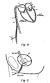
- the flexible instrument is preferably used for insertion through such small incisions and/or through a natural body lumen or cavity, if necessary, so as to locate the catheter at an internal target site for a particular surgical or medical procedure. Examples of such minimally invasive procedures include intravascular procedures, such as the repair of a cardiac valve.
- the introduction of the flexible instrument into the anatomy may be by percutaneous or surgical access to a lumen or vessel, or by introduction through a natural orifice in the anatomy.
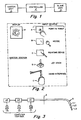
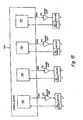
- Fig. 1 is a block diagram schematically illustrating the three main components of the remote control system of the present invention.
- a surgeon or user can input control actuations at master station 1, typically through an input device (not shown).
- Slave station 3 is separate and remote from the master station and controls the motion of the flexible instrument, in accordance with the user input from master station 1.
- Master station 1 and slave station 3 may be in relatively close proximity to each other, such as in the same operating room, or can be displaced from each other by miles.
- Controller 2 provides a telecommunications or electronic communications link coupled between the master station and the slave station. Controller 2 typically includes a computer. Controller 2 receives a command from the input device of master station 1 and relays this command to slave station 3.
- Fig. 6 is a schematic of the remote control system of the present invention.
- the system includes: (1) A master station comprising a user interface or surgeon's interface 11; (2) A slave station comprising a flexible instrument including shaft 30 which supports tool 18.
- Shaft 30 is connected to and is controllable from mechanically drivable mechanism 26, which in turn is engageably received by receiver 24, both of which are mechanically driven by drive unit 13, (alternatively mechanical drive 13); and (3) a controller or computation system 12 to translate a user's commands from user interface 11 to drive unit 13, which then drives the articulations of shaft 30 and tool 18.
- Fig. 6 illustrates a system where a user or surgeon can control shaft 30 and tool 18 by manipulating interface handles 30A of user interface 11. The movement of handle 30A causes responsive movement of tool 18 through the coordinating action of computation system 12.
- tool 18 can be a pair of graspers, scissors, staplers, etc. and manipulation of handle 30A can cause the jaws of tool 18 to open and close.
- Surgeon's interface 11 is in electrical communication with computing system 12, which is, in turn, in electrical communication with drive unit 13.
- drive unit 13 comprises a plurality of motors.
- the drive unit 13 is in mechanical communication with shaft 30 via conduit 23, which houses a plurality of mechanical cables driven by the plurality of motors in drive unit 13.
- drive unit 13 is solely in mechanical communication with shaft 30. Because of the mechanical communication with shaft 30, the electromechanical components in drive unit 13 are disposed in an area remote from the operative site, and preferably in an area outside the sterile field. Preferably, objects that are difficult to sterilize, e.g. motors or electromechanical components, are kept at a sufficient distance from the patient to avoid contamination.
- the sterile field has the rest surface of the operating table as its lower boundary.
- drive unit 13 is preferably located below the plane of the sterile field, i.e. below the rest surface of the operating table.
- the patient or subject may be further protected from drive unit 13 with a sterile barrier, such as a sterile cloth.
- a sterile barrier such as a sterile cloth.
- one aspect of the present invention provides a drive unit capable of remotely driving articulation of a flexible instrument, where the drive unit is remote from the subject and the flexible instrument.
- the slave station of the present invention employs, to a large part, a mechanical arrangement that is effected remotely and includes mechanical cables and flexible conduits coupling to a remote motor drive unit. This provides the advantage that the instrument is purely mechanical and does not need to be contained within a sterile barrier.
- the instrument may be autoclaved, gas sterilized or disposed in total or in part.
- drive unit 13 mechanically drives the flexible instrument (comprising shaft 30 and tool 18) through conduit 23, receiver 24 and mechanically drivable mechanism 26 (alternatively known as mechanically drivable interface or shaft mount).
- Conduit 23 houses a plurality of separate mechanical cables to mechanically connect drive unit 13 with receiver 24. The mechanical cables physically contact and drive the motions of shaft 30 and tool 18.
- Conduit 23 is engageable and disengageable with drive unit 13, i.e. attachable and detachable (see discussion of Fig. 49 , below). Although two conduits 23 are depicted here, it is understood that more or fewer conduits may be used, depending on the particular application.
- drive unit 13 comprises a plurality of motors, which drive the mechanical cables extending through conduit 23 and terminating at receiver 24.
- Receiver 24 interlockably receives mechanically drivable interface 26, which engages a separate set of cables extending through shaft 30 and at least one cable line operating tool 18.
- engaging drivable interface 26 with receiver 24 provides a mechanical (physical) connection from drive unit 13 to control certain motions of shaft 30 and tool 18.
- Receiver 24, which is supported by a carriage, is capable of moving along a linear path represented by the arrow 22 via rails 25.
- Cables in conduit 23 also mechanically drives the translation of receiver 24 along rails 25.
- the rails, and thus the linear translation extend at an acute angle with respect to the operating table, as well as the subject.
- This angular arrangement disposes the flexible instrument system in a convenient position over the patient. This arrangement also minimizes the number of components that operate within the sterile field, as drive unit 13 is maintained at a location remote from the sterile field.
- Fig. 49 shows a schematic perspective view of the cabling pathway for mechanically coupling one of an array of motors of a drive unit with a tool supported on a distal end of a shaft.
- the cabling pathway comprising a plurality of mechanical cables extends from the drive unit to the receiver.
- Another separate set of mechanical cables connects the mechanically drivable mechanism, situated at a proximal end of the shaft, to the tool and any controlled flexible segments positioned along the shaft.
- Interlocking the receiver with the mechanically drivable mechanism results in connecting the two separate sets of mechanical cables, thereby extending the cabling pathway from the drive unit to the distal end of the shaft.
- each of the mechanically drivable mechanism and the receiver can be considered as a coupler, which interlocks or couples with each other.
- Fig. 49 shows drive motor 675 positioned within a drive unit, such as drive unit 13 of Fig. 6 .
- the first cabling pathway comprises a set of cabling, which engages with and extends from drive motor 675 through idler pulley 682.
- the cables continue through idler pulleys 630 and 632 to drive wheel 622, which resides in receiver 506 (equivalent to receiver 24 of Fig. 6 ).
- a second separate set of cables extends about the drive wheel 624, guided by cam 626 and continues through flexible instrument shaft 528.
- Tool 534 links to shaft 528 via joint 601, which provides a wrist pivot about axis 532 in the direction of arrows J4.
- the two separate sets of cables are interlocked by interlocking drive wheel 622 of receiver 506 with drive wheel 624 of mechanically drivable mechanism 526 (equivalent to drivable mechanism 26 of Fig. 6 ).
- the interlocking involves slotting a blade 606 into a corresponding slot within wheel 624 (see further discussion of Fig. 43 below).
- the interlocking mechanism can comprise a magnetic attachment, where a first series of magnets in the mechanically drivable mechanism interacts with a second series of magnets in the receiver. Each series of magnets can couple with the mechanical cables.
- Fig. 49 also shows the output of motor 675 at a coupler pulley 677, which is adapted to rotate with an output shaft of the motor.
- the rotational arrow 680 indicates this rotation.
- Fig. 49 only illustrates one cabling pathway. It can be appreciated that several other cabling pathways can be constructed and arranged to control other motions of the shaft and tool through other motors of the drive unit.
- Fig. 2 schematically depicts the components of master station 1.
- Master station 1 can include any one or a combination of input devices A-E and a display F.
- Input device A is a point-and-touch device.
- Input device B is a computer mouse.
- Input device C is a pointing device that may employ a pen or stylus.
- Input device D is a joystick.
- Input device E is a hand interface, that provides finer control of the shaft, or a tool positioned at the distal end of the shaft.
- input device E features handles that control the motion of the shaft and a tool.
- the master station features input device 11 comprising handles 30A.
- Handles 30A are held by the surgeon, who can then torque, translate or rotate catheter member 30 and tool 18 by performing the corresponding motions on handles 30A.
- a rotation of a handle 30A via rotation of the surgeon's hand can control rotation of, for example, the outer shaft 32 about the co-axis.
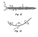
- Flexing or bending of flexible section 42 can be controlled by the surgeon flexing his hand at the wrist and activating flex cable 52, as shown in Fig. 8 (see discussion of Fig. 8 , below).
- a surgeon can manipulate tool 18 by, for example, closing and opening the jaws of handles 30A to simulate opening and closing of jaws of tool 18.
- Display F provides a direct video image of the site surrounding the distal end of the shaft.
- An endoscope supporting a camera is inserted into the body of a subject, providing the video feed of the operative site.
- the camera can be mounted on or housed at the distal end of the shaft.
- the camera can provide a view of the operative site, or may be positioned away from the site to provide additional perspective on the surgical operation.
- Other detection systems may be used for providing different images useful in assisting the surgeon in performing the medical procedure.
- various signals may be utilized in conjunction with or in alternative to the video image, such as ultrasound (echocardiography, Doppler ultrasound), angiography, electrophysiology, radiology or magnet resonance imaging (MRI).
- ultrasound echocardiography, Doppler ultrasound
- angiography angiography
- electrophysiology CAD
- radiology radiology
- magnet resonance imaging MRI
- an audio signal could be used for guiding the shaft.
- Fig. 6 illustrates a computer system 12, which interfaces the surgeon interface 11 and drive unit 13 of the slave station.
- the drive unit 13 contains a series of motors that control cables coupled by way of conduit 23 to control certain movements of the catheter apparatus.
- the controller 12, depicted in Fig. 6 essentially links the slave station to the surgeon interface.
- the user input device electronically sends commands, which are translated by the controller and sent to drive unit 13.
- Drive unit 13 then mechanically effects the motion of the shaft, particularly the flexible segment and the tool.
- Figs. 14 and 15 are block diagrams of an embodiment of a motor control system that may be employed in a drive unit of the present invention.
- the master station side there is at least one position encoder associated with each of the degrees-of-motion or degrees-of-freedom. At least some of these motions are associated with a motor that may be represented by a combination of motor and encoder on a common shaft. Thus, controlling the motor ultimately controls such parameters as a force feedback to the master station.
- the present system can comprise a multiaxis, high performance motor control system, which can support anywhere from 8 to 64 axes simultaneously using either eight-bit parallel or pulse width modulated (PWM) signals.
- PWM pulse width modulated
- the motors themselves may be direct current, direct current brushless or stepper motors with a programmable digital filter/commutator. Each motor accommodates a standard incremental optical encoder.
- Host computer 700 is connected by digital bus 702 to interface board 704.
- Host computer 700 can be, for example, an Intel microprocessor based personal computer (PC) at a control station preferably running a Windows NT program communicating with the interface board 704 by way of a high-speed PCI bus 702 (5.0 KHz for eight channels to 700 Hz for 64 channels)
- the PC communicates with a multi-channel controller electronic card, providing up to 28 axes of motion control, each with a 1.5kHz sampling rate.
- the controller is efficient, scalable and robust.
- Interface board 704 can be a conventional interface board for coupling signals between digital bus 702 and individual module boards 706.
- Each module board 706 includes four motion control circuits 710, as illustrated in Fig. 15 .
- Each circuit 710 can be, for example, a Hewlett-Packard motion control integrated circuit, such as an IC identified as HCTL1100.
- Fig. 15 depicts a further sub unit of this system, particularly a power amplifier sub unit 712.
- Power amplifier sub unit 712 is based on National Semiconductor's H-bridge power amplifier integrated circuits for providing PWM motor command signals.
- Power amplifier 712 is associated with each of the blocks 710, which couples to a motor X.
- motor X Associated with motor X is encoder Y. Although the connections are not specifically set forth, it is understood that signals intercouple between block 710 and interface 704 as well as via bus 702 to host computer 700.
- the motor control system may be implemented in two ways.
- the user may utilize the four types of control modes provided by the motor control sub unit 706: positional control; proportional velocity control; trapezoidal profile control; and integral velocity control.
- positional control positional control
- proportional velocity control positional velocity
- trapezoidal profile control trapezoidal profile control
- integral velocity control any one of these modes can involve simply specifying desired positions or velocities for each motor, and necessary control actions are computed by motion control IC 710 of the motor control sub unit, thereby greatly reducing the complexity of the control system software.
- the user may choose the second method in which the servo motor control software is implemented at the PC control station. Appropriate voltage signal outputs for each motor are computed by the PC control station and sent to the motor control/power amplifier unit (706, 712). Even if the computation load is mostly placed on the PC control station's CPU, the use of high performance computers as well as high speed PCI bus for data transfer can overcome this problem.
- Fig. 16 describes the overview of the control algorithm for the present invention, mapping out motions of the catheter to that of the surgeon's interface handle in three-dimensional space. Such precise mapping can create the feel of the tool being an extension of the surgeon's own hands.
- the control algorithm can assume that both the surgeon's interface as well as the catheter always starts at a predefined position and orientation, and once the system is started, it repeats a series of steps at every sampling.
- the predetermined positions and orientations relate to the initial positioning at the master station.
- the joint sensors (box 435), which are optical encoders in the present embodiment, of the surgeon's interface system are read, and via forward kinematics (box 410) computation of the interface system, the current positions (see line 429) and orientations (see line 427) of the interface handle can be performed.
- the translational motion of the surgeon's hand motion is scaled (box 425) whereas the orientations are kept identical, resulting in desired positions (see line 432) and orientations (see line 434) of the catheter's tool.
- the results are then inputted into the inverse kinematics algorithms for the catheter's tool, and finally the necessary joint angles and insertion length of the catheter system are determined.
- the motor controller (box 420) then commands the corresponding motors to positions such that the desired joint angles and insertion length are achieved.
- Fig. 16 provides an initial start position for the handle, indicated at box 440.
- the output of box 440 couples to a summation device 430.
- the output of device 430 couples to scale box 425.
- Initial handle position 440 is established by first positioning the handles at the master station so as to establish an initial master station handle orientation in three dimensional space. Initial handle position 440 is then compared to the current handle position at device 430. The output from device 430 is then scaled by box 425 to provide the desired tool position on line 432 coupled to the catheter inverse kinematics box 415.
- the slave station comprises a flexible instrument, e.g. a shaft optionally supporting a tool at its distal end, for insertion into a subject.
- the flexible instrument is a catheter.
- Catheter as defined herein refers to a shaft adapted for, but not necessarily limited to, insertion into a subject, and more particularly for insertion into natural body lumens, canals, vessels, passageways, cavities or orifices.
- the shaft is typically tubular, but any elongate shaft may be adaptable for insertion into the subject.
- the shaft can be solid or hollow.
- a subject can be a human, an animal, or even individual organs or tissues that are dead or living.
- the introduction of the flexible instrument into the human or animal body may be by percutaneous or surgical access to a lumen or vessel, or by introduction through a natural orifice in the body.
- natural lumens include body vessels such as a blood vessel (artery, chamber of the heart or vein), urinary system vessels (renal collection ducts, calix, ureter, bladder or urethra), hepatobilliary vessels (hepatic and pancreatic ducts, chyle ducts; common or cystic duct), gastrointestinal tract (esophagus, stomach, small and large intestine, cecum and rectum), gynecological tract (cervix, uterus, fallopian tube or milk ducts and mammary canals of breast), nasopharynx (eustacean tube, sinuses, pharynx, larynx, trachea, bronchus, bronchiole, tear duct) seminal vesicle, spinal
- the shaft can be constructed from a standard 9 French (2.67mm diameter) coronary guiding catheter.
- the shaft may support various forms of tools, typically at its distal end.
- a user can manipulate tool 18 along a single axis of motion where tool 18 is, for example, a grasper, scissors or general mechanism (such as a stapler or clip applier).
- tool 18 is, for example, a grasper, scissors or general mechanism (such as a stapler or clip applier).
- a grasper such as a stapler or clip applier
- general mechanism such as a stapler or clip applier
- tools may be located at a position other than the distal end of the shaft.
- the tools aid in carrying out various surgical or medical procedures, including, but not limited to:
- Exemplary objects implanted in a subject include staples, tacks, anchors, screws, stents, sutures, and a variety of other objects implanted by physicians and medical professionals.
- the procedure of delivering can further include delivery of agents including, but not limited to:
- the flexible instrument can be used as a sensor.
- Parameters that may be sensed include, but are not limited to:
- the slave station also comprises a drive unit capable of articulating the flexible instrument, particularly the shaft and the tool.
- the drive unit is to drivably coupled to a receiver for receiving the mechanically drivable mechanism. In one embodiment, this coupling occurs via cables.
- the drive unit is electronically controllable from the master station, as there is an electronic link between the drive unit and a user input device of the master station.
- the drive unit When the receiver receives the mechanically drivable mechanism, the drive unit then has a direct pathway for controlling operation of the shaft and tool. If the shaft has a controlled flexible segment, the drive unit is capable of activating or bending the flexible segment via the mechanically drivable mechanism, for actuation of the shaft, the tool and positioning of the tool at an operative site within the subject. In one embodiment, drive unit is capable of bending the flexible segment via a first set of cables which couple the drive unit to the receiver, and a second set of cables which drivably couple the mechanically drivable mechanism to the flexible segment and the tool.
- One aspect of the present invention provides a remote controlled outer (guide) catheter having a distal end disposed at or in an area about an operative site, preferably in the immediate area of an operative site.
- a coaxial inner (working) catheter nested within the outer catheter can then be used to perform the surgical or medical procedure.
- Previous surgical procedures involve insertion of a trocar or cannula into the subject at a relatively short depth to provide an opening for receipt of the catheter, which is then guided to the operative site.
- the catheter is not disposed at the immediate area around the operative or target site. Thus, if the surgeon needs a second catheter, the first catheter must be withdrawn and the second catheter is guided to the target site. Such repeated insertions can aggravate trauma experienced by the patient.
- the feature of the present invention employs an outer catheter disposed at the target site, which allows more than one shaft to be inserted and withdrawn with minimal irritation or trauma experienced at the passageway leading to the operative site.
- the outer catheter housing a coaxial inner catheter is disposed at the target site.
- the inner catheter can immediately function at the operative site. If a second inner catheter is required, the first inner catheter can be quickly withdrawn through the outer guide catheter and the second inner catheter inserted through the outer catheter with minimal injury to the subject.
- FIG. 3 depicts a system of remote controlled coaxial catheters. This system employs three coaxial or nested catheters L1-L3. Dashed line I represents an incision or entry point of the patient. Fig. 3 also illustrates computer controls C1-C3, which are outside of and remote from the patient. "Remote from the patient” refers herein to any location outside the sterile field. Computer controls C1-C3 are associated with corresponding actuators A1, A2 and A3, (i.e. drive units) which in turn are associated with shafts L1-L3, respectively. Thus, in FIG.
- the controller C1 controls an actuator A1 which, in turn, controls a certain action or movement of the outer shaft L1.
- actuator A1 which, in turn, controls a certain action or movement of the outer shaft L1.
- shafts L1-L3 can be independently controlled by one actuator, which independently drives specific cables leading to each of shafts L1-L3.
- the present invention allows shafts L1-L3 to be remote controlled independently from each other.
- shaft L1 can remain stationary while shaft L2 undergoes linear translations or rotations about the co-axis.
- the distal end of shaft L3 can also carry out these motions as well as a bend or flex independent of shafts L1 or L2.
- Shaft L2 can be controlled to, for example, provide a rotational movement so as to enable rotation of a distal tool.
- the control of a tool supported at a distal end of a shaft is independent of the motions of shafts L1-L3.
- all shafts L1-L3 can undergo a simultaneous bend or deflection at a single operative segment or flexible segment, labeled as O in Fig. 3 .
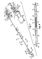
- Fig. 7 illustrates the outer and inner shafts.
- shaft 30 comprises an outer shaft 32 housing and coaxial with inner shaft 34.
- Outer shaft 32 and inner shaft 34 extend from and within mechanically drivable interface 26.
- Interface 26 mechanically couples a drive unit (shown in Fig. 6 ) with shaft 30.
- Interface 26 further comprises a series of control elements, such as pulleys 64 and 72, which run cable lines 52 and 28, and gears 60 and 68 for controlling rotation of the shafts.
- Control element 60, or gear 60 in interface 26 encircles outer shaft 30 and controls the rotational position of guide shaft 32 in the direction indicated by rotational arrow 65.
- Gear 68 in interface 26 encircles inner shaft 34.
- Control element 68 controls the rotational position of the inner shaft 34 in the direction indicated by rotational arrow 69.
- Rotational arrows 65 and 69 indicate rotation about the "shaft lumen axis", i.e. the axis tangential to the cross section of the shaft lumen.
- control element 68 would control the rotational position of the tool about the shaft lumen axis as well. If the distal end were flexed, the shaft would curve and rotation of the shaft would cause the tool to trace a circle, and not cause the tool to rotate about its internal axis. As described below, another control can be positioned in the mechanically drivable interface for solely controlling the tool independent of the shaft controls.
- a flexible instrument comprises a shaft having at least one section that is flexible.
- Flexible refers herein to a material that is inherently and sufficiently deformable to readily pass atraumatically through a natural body lumen, cavity, vessel, orifice and the like.
- the shaft is sufficiently flexible to readily flex and/or conform to a pathway in an anatomic vessel, lumen, cavity or the like.
- Non-flexible or rigid catheters can be distinguished from flexible instruments by the following test. By knowing the dimensions of a rigid catheter and the point of entry into the subject, one can calculate the position of the catheter end point inside the subject. In contrast, even if the dimensions and point of entry of a flexible shaft were known, the position of its end point within the subject cannot be calculated with precision because the flexible shaft may bend.
- Flexible instruments of the present invention can also be distinguished from other known catheters that mimic bending motions solely through a series of rigid sections linked by joints.
- a "bend" is not the result of a deformation of the catheter material but by the pivoting or rotation of two rigid sections about a joint.
- flexible instruments of the present invention include at least one flexible segment that is bendable without requiring the use of joints. The bending is remotely controlled, allowing deflection at these flexible segments away from the lumen axis of the segment. Bending in this sense is possible by choice of inherent flexibility of the instrument coupled with an induced deflection at the flexible segment. Inherent flexibility can be achieved by choice of a deformable material, such as.
- Inherent flexibility can also be achieved by designed construction using a more rigid material, for example carving out segments of the material, i.e. slotting the material, such that the material is sufficiently thin for bending.
- the flexible instrument can comprise rotatable or pivotable joints, but the flexible capability is not the result of employing such joints, but by the deformability of the shaft material.
- the bending is remotely controlled via a drive unit drivably coupled to the receiver for receiving a mechanically drivable mechanism or shaft mount. The shaft mount is then drivably coupled to the controlled flexible segment, thereby providing a drivable bending mechanism
- the shaft can be tailored for a particular body lumen. Factors of the shaft construction include resiliency of the walls of the lumen, curvature of the passageway, location of the target site, diameter of the lumen, etc.
- a shaft for passing through a colon can be, but is not necessarily, manufactured from a material that is less deformable than a shaft for passing through a small, delicate blood vessel. Lumens that present passageways of high curvature may also require a more easily deformable, and thus more flexible, shaft than does a relatively straight lumen. Deformability of the shaft can also be tailored by varying the dimensions, particularly the diameter, of the shaft.
- a user can controllably bend or flex at least a section of the flexible instrument.
- this controlled bend can be provided by a shaft having at least one flexible segment, alternatively a controlled flexible segment.
- a user can induce a bend in the shaft at the flexible segment.
- the bend at the flexible segment is actuated mechanically, thus distinguishing this aspect of the present invention from prior art catheters where the bends are induced electrically.
- U.S. Patent No. 5,238,005 describes a bending mechanism caused by varying the electrical resistance through a catheter material having a negative coefficient. Heating one area of a catheter by increasing its electrical resistance results in contraction of that area, causing the catheter to deflect toward the contracted area. In contrast, the present catheter responds to mechanical forces.
- Figs. 7 and 8 illustrate one embodiment of a controlled flexible segment.
- Fig. 7 shows controlled flexible segment 42 residing between proximal end 36 and distal end 38 of shaft 30. It is understood, however, that flexible segment 42 can be positioned on any portion of shaft 30.
- Fig. 8 provides an expanded view of flexible segment 42 and illustrates one construction of flexible segment 42.
- flexible segment 42 is constructed by providing inner shaft 34 as a flexible material nested within outer shaft 32. Outer shaft 34 is split into rigid proximal and distal sections 36 and 38, both encircling inner shaft 34.
- flexible segment 42 is the gap between proximal and distal sections 36 and 38.
- Shrink-wrap pieces 44 and 45 extend over the respective facing ends of the proximal and distal shaft sections 36 and 38 and adhere these facing ends to the flexible inner shaft.
- flexible segment 42 may be in the form of a metal coil of diameter similar to the diameter of outer shaft sections 36 and 38.
- outer shaft 32 can be constructed of a flexible material as well, although its flexibility is preferably less than that of inner shaft 34.
- flex wire 52 extending from mechanically drivable mechanism 26 and through flexible segment 42, terminating at point 54 of distal end 38 (see Fig. 8 ).
- Flex wire 52 is preferably disposed between inner shaft 34 and outer shaft 32.
- Fig. 8 shows termination point 54 residing on the outer surface of distal end 38, although conceivably other surfaces of distal end 38 can serve as termination points.
- the other end wire 52 resides within drivable mechanism 26 on control pulley 64. Turning pulley 64 has the effect of pulling wire 52 in a direction parallel to shaft 30 pointing towards drivable mechanism 26. Because wire 52 is terminated at 54, this pull causes the distal shaft section 38 to deflect in a direction indicated by the arrow 55, as shown in FIG. 7 .
- More than one flex wire can be spaced about the circumference of outer shaft 32 to allow bending along multiple directions different from arrow 55 yet orthogonal to shaft 30.
- Fig. 11 illustrates an embodiment where two cables actuate bending the bending.
- Fig. 11 is a cross-sectional view of outer shaft 32 receiving inner shaft 34 at termination point 52.
- Two cables 52 A and 52 B terminate on outer 32 on opposite sides of distal shaft section 38. Cables 52A and 52B may be manipulated so as to deflect the distal shaft section in opposite directions, in a manner described previously.
- Those of ordinary skill in the art can readily appreciate that employing multiple cables results in a shaft capable of deflecting in any number of directions.
- Fig. 12 depicts a distal end of shaft 30, showing operative segment O (e.g. flexible segment 42) and tool 18.
- Fig. 12 shows two coaxial catheters including an outer shaft O1 (such as outer shaft 32) and inner shaft 02 (such as inner shaft 34). Also disclosed are two stainless steel cables, including outer cable 03 and inner cable 04.
- Outer shaft O1 provides translational and rotary motion.
- Outer cable 03 which is disposed between outer and inner shafts O1 and 02, provides the lateral rotation (or yaw motion) of tool 18.
- Inner shaft 02 rotates tool 18 and inner cable 04 actuates the jaws of tool 18.
- the tool of Fig. 12 provides a single degree-of-freedom in order to actuate a gripper, scissors or generic mechanism (such as a stapler or clip applier).
- An example may be a bi-directional gripper 5mm in length and 2.67 in diameter.
- the system comprising the flexible instrument comprises tool or mini-tool (18), the operative segment (42), the catheter stem (32, 34), the coupler (24, 26) comprising the mechanically drivable mechanism 26 and the receiver 24, the drive unit (13), the controller (12) and the surgeon's interface (11).
- the coupler provides a translational degree-of-freedom achieved by using a sliding mechanism, i.e. rails 25, onto which the coupler is mounted, as illustrated in Fig. 6 .
- the operative or controlled flexible segment provides a number of articulations in order to position and orient tool 18.
- the catheter (30) has four (4) degrees-of-freedom, i.e. one translation and three rotations, as shown in Fig. 7 .
- a fifth degree-of-freedom may be provided by the actuation of the mini-tool, as tool 18 can provide at least a single axis of motion for a grasper, scissors or general mechanism (such as a stapler or clip applier).
- the combination of one translation and two rotations allows the operative segment to arbitrarily position the mini-tool in three dimensional space.
- a final degree-of-freedom rotates the mini-tool axially.
- Fig. 13 schematically illustrates the various degrees of freedom by which the catheter can be manipulated, particularly the axial and lateral rotations, or the translation motion allowing independent control of the tool position within the surgical space, as well as axial rotation of the tool.
- the system of Fig. 6 provides a physician with seven independent command inputs, including position ( ⁇ i , ⁇ i , z i ), orientation ( ⁇ i , ⁇ i , ⁇ i ) and tool grip angle ⁇ i .
- ⁇ is chosen as a scaling value
- Fig. 42 is a perspective view of another embodiment of the slave station for a remote controlled flexible instrument.
- Fig. 42 depicts flexible instrument system 500 supported from support bracket 502, which extend to the operating table (see Fig. 6 ).
- the support bracket is supported from the side of the operating table and may be adjustable in position relative to the operating table, to dispose system 500 in a convenient position over the patient.
- bracket 502 is secured to the operating table at one end.
- the other end of bracket 502 supports the entire flexible instrument by means of a two-piece structure similar to that described in copending U.S. Provisional Applications Serial No. 60/279,087 filed March 27, 2001 .
- a knob may be provided on support base 504, not shown in Fig. 42 .
- system 500 can be positioned at an acute angle with respect to the operating table.
- Flexible instrument system 500 comprises flexible instrument 510 having a shaft 528 extending to mechanically drivable mechanism 526, which interlocks with base (or receiver) 506.
- Base 506 is supported on carriage 508.
- Carriage 508 in turn is adapted for linear translation and supported by elongated rails 512 and 514. Rails 512 and 514 terminate at one end via end piece 516, which provides further support. Support base 504 terminates rails 512 and 514 at their other end.
- Carriage 508 includes bearings or bushings 509 that support the carriage from rails 512 and 514.
- Flexible instrument system 500 employs two separate cable bundles for mechanically driving the flexible instrument along rails 512 and 514.
- Pulley 521 (dotted outline), residing within carriage control module 520, receives a first pair of cables 518. Pulley 521 also receives a second set of cable (see cabling sections 513 and 515 of corresponding Fig. 43 ), which runs through carriage 508 to a further pulley 522 supported by end piece 516. The second set of cables controls the translational motion of carriage 508 and terminates at point 519 (see Fig. 45 ).
- Fig. 42 also shows a set of cables 524 for driving control elements, e.g. pulleys within receiver 506. These control elements move the shaft and the tool in several degrees-of-freedom.
- Arrow J1 indicates the linear translation via module 520.
- Rotational arrow J2 indicates rotation of flexible shaft 528 of flexible instrument 510 about the inner axis parallel with the shaft length.
- Arrow J3 represents the flexing or bending of flexible shaft 528 at controlled flexible segment 530.
- flexible segment 530 is positioned directly adjacent tool 534 at the distal end of shaft 528.
- Arrow J4 represents the pivot action of a wrist joint, which links tool 534 to shaft 528, about axis 532.
- tool 534 is exemplified as a grasper, and arrows J5 and J6 represent the opening and closing actions of the tool jaws. Motions indicated by arrows J2-J6 are controlled from cabling 524 originating at receiver 506.
- Fig. 42A provides an enlarged perspective view of the distal end of shaft 528 including flexible segment 530 and tool 534.
- Tool 534 comprises upper grip or jaw 602 and lower grip or jaw 603, both supported from link 601.
- Base 600 is affixed to or integral with flexible shaft 528.
- Link 601 is rotatably connected to base 600 about axis 532.
- a pivot pin may be provided for this connection.
- Upper and lower jaws 602 and 603 are rotatably connected to link 601 about axis 536 and again, a pivot pin can provide this connection.
- Fig. 42A shows eight cables at 538 extending through the hollow inside of shaft 528 for control of tool 534 and flexible segment 530. Two of these cables operate the bend of flexible segment 530, two cables operate one of the jaws 602, two cables operate the other of the jaws 603 and the last two cables operate the wrist action about the axis 532. All of these cables travel through the hollow shaft 528 and through appropriate holes in flexible segment 530, e.g. wire 525, as well as holes in base 600. Each of these pairs of cables operates in concert to open and close jaws, pivot about the wrist, and bend flexible segment 530.
- One pair of cables travels through shaft 528 and through appropriate holes in the base 600, wrapping around a curved surface of the link 601 and then attaching to the link. Tension on this pair of cables rotates the link 601 along with the upper and lower grips or jaws 602 and 603 about axis 532.
- Flexible segment 530 Bending of flexible segment 530 is provided via diametrically disposed slots 662, which define spaced ribs 664. Flexible segment 530 also has a longitudinally extending wall 665 through which cabling may extend, particularly for the operation of the tool.
- One of the pairs of cables of bundle 538 controlling flexible segment 530 terminates where base 600 intercouples with shaft 528. This pair of cables works in concert to cause bending as indicated by arrow J3, i.e. in a direction orthogonal to the pivoting provided at wrist axis 532. In Fig. 42A only one cable 525 of two is illustrated.
- Fig. 43 is an exploded prospective view showing carriage 508, receiver 506 and drivable mechanism 526.
- Carriage 508 is adapted for motion along rails 512 and 514.
- Pulleys 521 and 522 receive cabling, i.e. cable sections 513 and 515, which terminate at the carriage base at point 519. Other sections of this cable extend through an elongated hole or passage within carriage 508.
- Receiver 506 and drivable mechanism 526 each comprise enclosed housings supporting a plurality of control elements, such as intercouplable drivewheels and associated pulleys or cams.
- Inter-engaging gears 540 and 542 are supported respectively in the modules 506 and 526.
- a pair of cables from bundle 524 engages pulley 544 (see Fig. 45 ) which, in turn, drives gear 540, and which further, in turn, drives gear 542 for providing rotation of shaft 528.
- Collar 546 is provided at the terminus of the proximal end of shaft 528 for supporting shaft 528, which is driven by gear 542. Cabling extending through collar 546 and shaft 528 couple mechanical actions from drivable mechanism 526 through the flexible instrument shaft 528 to the distal end thereof.
- Drivable mechanism 526 interlocks with receiver 506, providing the mechanical connection that allows the drive unit to run cabling in flexible instrument 510.
- Posts 616 protruding from the housing of receiver 506 are adapted to releasably mate with holes 618 in drivable mechanism 526. Posts 616 and holes 618 to interlock with each other, but may be released from each other via side-disposed buttons 620, as illustrated in Fig. 46 .
- Fig. 43 also shows the cam locking screws 615.
- Fig. 44 is a partial broken away rear elevational view of interlocking interfaces as seen along line 44-44 of Fig. 42 .
- Fig. 44 shows alignment posts 616 each having a groove 617, which is engaged by the corresponding button 620.
- Button 620 is in the form of a plate member biased to a locked position by means of spring 621.
- a plate for button 620 has a keyhole slot for receiving and holding post 616 therein.
- Button 620 may be manually depressed to release posts 616 and enable ready detachment of drivable mechanism 526 from receiver 506.
- a retaining pin 625 may also be used to limit the travel of the button between in and out positions.
- Fig. 45 is cross-sectional side view through the interconnecting modules taken along line 45-45 of Fig. 42 .
- Fig. 45 shows details of drive wheels (or pulleys) in the modules 506 and 526.
- Drive wheels 622 are supported within the housing of receiver 506.
- Drive wheels 622 receive cabling for controlling the motions of the shaft and the tool, where the cable protrudes from cable bundle 524 in Fig. 43 .
- Each of these pairs of cables is controlled from a corresponding motor, which is part of the drive unit (see discussion of Fig. 49 , below).
- Fig. 45 also shows output blades 606, previously shown in Fig. 43 , which extend into corresponding slots 608. These slots are disposed in respective intergaging drive wheels 624 of the drivable mechanism 526. Blades 606 have a rectangular end construction for engaging with similar rectangular slots 608 associated with the module 526. Fig. 45 also shows the gears 540 and 542 in engagement to allow drive to occur from bundle 524.
- Figs. 45 and 46 show a series of idler cams 626, one associated with each of drive wheels 624.
- Fig. 46 is a plan cross-sectional plan view through receiver 506 as taken along line 46-46 of Fig. 45.
- Fig. 46 shows the placement of cams 626.
- a cable wraps around each of drive wheels 624 and is held in position by its associated cam 626.
- Fig. 46 also shows all of the cables running parallel to each other at region 627, where the cables run from respective drive wheels 624, through collar 546 and extending down inside shaft 528 to the distal end. With the use of the placement and adjustment of cam 626, the cables are all directed in a manner to easily couple into shaft 528.
- cams 626 has an off-center axis 631. As viewed in Fig. 46 , cam 626 may be rotated clockwise to tighten its associated cable. Rotation counterclockwise loosens the tension. Cam locking screws 615 secure cam 626 in an adjusted-to position (see Fig. 48 , a cross-sectional view taken along line 48-48 of Fig. 47). Fig. 48A is a cross-sectional view taken along line 48A-48A of Fig. 48 . As depicted in Figs. 46 and 48A , the cable associated with each wheel 624 may be secured in a cable clamping hole 633 via a cable clamping screw 635. A similar clamping arrangement is associated with wheels 622. A roll pin fixes each wheel 622 to each spindle 607.
- Fig. 47 is a cross sectional plan view taken through receiver 506, as taken along line 47-47 of Fig. 45 .
- the cross-sectional view of Fig. 47 illustrates drive wheels 622 associated with receiver 506.
- Drive wheels 622 receive cabling from cable bundle 524.
- Each of a pair of idler pulleys 630 are associated with drive wheels 622.
- idler pulleys 632 are used for directing the cable to idler pulleys 630 and from there to drive wheels 622.
- Fig. 48B is a fragmentary plan view of a drive wheel engagement slot by itself as seen along line 48B-48B of Fig. 48A .
- the cross-sectional views of Figs. 48A and 48B illustrate drive wheels 622 within receiver 506 having associated end blades 606.
- End blade 606 is a screwdriver-type blade that engages a slot previously identified as slot 608 in Fig. 43 .
- This slot 608 is in drive wheel 624 of receiver 526.
- slot 608 displays a tapered portion. The tapered portion allows easy registration of end blade 606 and slot 608, and thus easy registration between drive wheel 622 and drive wheel 624.
- the bending or deflection of the shaft can be actuated by mechanical means such as a wire extending along a length of the shaft.
- mechanical means such as a wire extending along a length of the shaft.
- actions at the distal end of shafts may be controlled by mechanical elements, such as cables, wires or other tendons.
- Fig. 41A illustrates shaft 850 having a central lumen. Residing in the central lumen is an operative or controlled flexible segment O, in the form of a plurality of spaced electromagnetic rings 852, separately labeled as R1, R2, R3 and R4. Each of rings R1-R4 is associated with wires 854, similarly labeled as wires W1, W2, W3 and W4. Rings 852, once energized, provide bending of shaft 850 at flexible segment O.
- Figs. 41A and 41D are meant to be schematic, while Figs. 41B and 41C are actual implementations for actuation of the rings by means of coils or windings 853.
- each ring may be electrically energized via a winding 853 associated therewith.
- Fig. 41B shows a fully wound winding
- Fig. 41C shows a half wound winding.
- Ring 852 may also have two separate half wound coils on opposite sides thereof.
- Wires 854 (in pairs) are selectively energized to energize windings 853 on the rings, which in turn, provide either attraction or repulsion of the rings.
- Fig. 41D illustrates the results of regions of rings 852 being energized to attract or repel adjacent rings. For example, a certain direction of current flow through windings 853 can create an attraction of the coils at the bottom and a repulsion of coils at the top. This cooperative action causes a bending at the operative or controlled flexible segment O.
- a controlled flexible segment may be provided, not necessarily for action at a target site, but to control certain movements of the catheter to assist in reaching a target site.
- Figs. 4 and 5 illustrate the advantages of a flexible instrument, particularly a catheter having controlled flexibility via controlled flexible or operative segments, for use in performing a procedure or for guiding the instrument through a natural body lumen.
- Fig. 4 provides a schematic cross-sectional diagram, illustrating a catheter K for use in mitral valve repair, to be discussed in more detail below.
- Fig. 4 also shows catheter K supporting a tool 18 for carrying out certain procedures at the mitral valve annulus, also described in further detail below.
- catheter K is shown entering the femoral vein V by a percutaneous access at S. From the femoral vein V, catheter K must bend prior to entering the right atrium R.
- Catheter K then passes through a septal wall of the heart to the left atrium L, which is directly above the mitral valve M.
- the operative segment of the catheter K is illustrated at O and is positioned near the very distal end of the catheter K.
- a user can controllably bend catheter K at the operative segment, to perform a procedure with tool 18.
- the ability to controllably bend catheter K prevents tool 18 from conceivably being trapped within femoral vein V, causing damage to the walls of vein V.
- Fig. 5 provides a schematic cross-sectional diagram illustrating a surgical procedure where catheter K1 enters a natural body orifice, such as the urethra for carrying out procedures in, for example, the bladder.
- catheter K1 is shown extending into bladder B1.
- the computer controlled segment identified as operative or flexible segment O in Fig. 5
- Bladder B1 being an open cavity, does not have lumens leading from the urethra that would naturally guide a catheter towards any particular operative site.
- catheter K1 can bend in any direction and not necessarily in the direction of the operative site.
- the distal end of catheter K can be rigid or be "passively" flexible, i.e. made of a flexible material and not necessarily controlled for flexure under remote computer control.
- the catheter K may be fed through the femoral vein by direct surgeon manipulation, in which case only the operative segment O is under computer control from a master station.
- the catheter may translate linearly through the vein under remote master station control, where the catheter can have other operative segments disposed at different locations of catheter K. Each of these operative segments can be controlled from a master station for assistance in the guiding of the catheter to a predetermined target site.
- the catheter may be inserted manually and also have remote computer control for at least limited linear translation.
- Figs. 3A-3C show different embodiments of flexible instruments with multiple operative or controllable flexible segments. Shafts having multiple operative segments can be very useful for procedures in a body cavity, as discussed previously, but can also be useful in navigating the shaft through intricate or delicate body lumens.
- Figs. 3A-3C schematically illustrate controller CT and a slave portion of the system comprising actuators or drive units A1-A4 and shaft KA, KB or KC having three operative segments O1-O3.
- a surgeon inputs commands from a master station to cause certain corresponding movements of the shaft at the slave station.
- a surgeon's manipulations at the master station are coupled to controller CT where these manipulations are mapped to actions at operative segments O1-O3.
- a surgeon at an appropriate input device, may carry out a first manipulation to control a segment O1, a second different manipulation to control the segment 02 and still a third manipulation to control the segment 03, either simultaneously or sequentially.
- a fourth manipulation may control the tool G.
- Fig. 3A shows shaft KA having three operative segments, O1, 02, and 03, and tool G at its distal end.
- Actuators A1, A2 and A3 are associated respectively with operative segments O1, 02 and 03.
- Actuator A4 controls tool G.
- Each of actuators O1-O3 is controlled from controller CT.
- Operative segments O1, 02 and 03 are spaced a certain distance apart from each other, allowing shaft KA to simultaneously experience controlled bends. This arrangement may be necessary for lumens with multiple bends, or for hard to reach operative sites.
- Fig. 3B shows catheter KB having tool G1.
- three operative segments O1, 02 and 03 are spaced from each other along the length of catheter KB.
- Segments O1-O3 can be controllably bent to form an arc having an imaginary radius point P.
- catheter KC in Fig. 3C employs three operative segments O1-O3, which are contiguous. The radius of curvature can be increased.
- non-operative segments of the catheter in Figs. 3A-3C can comprise either a flexible or a rigid material. It can be appreciated that one or more controlled flexible segments can be incorporated in the shaft, depending on the particular application.
- Another aspect of the present invention provides a remote controlled flexible instrument operable within the sterile field, and disposable after use.
- the sterility of reusable medical instruments and implements are maintained by well-known methods such as exposure to sterile solutions and/or autoclaving.
- it can be more cost effective to manufacture them from low cost materials and dispose them after a single use, or use on a single patient.
- its manufacture from low cost materials still results in a costly product due to the intricate nature of the individual parts and the labor required to manufacture complex components.
- the present design allows the use of injection-molded plastic parts.
- the disposable component can be easily and quickly engaged into and disengaged from a non-disposable, reusable base.
- the components can be locked onto the base by snapping or interlocking matched parts, without having to thread cable wires or attach any intricate components.
- a disposable implement comprising a disposable mechanically drivable mechanism, a disposable shaft extending from the drivable mechanism, and optionally a disposable tool supported on a distal end of the shaft.
- mechanically drivable mechanism 26 comprising gears 60 and 68 and pulleys 64 and 72, can be manufactured from injection molded plastic, as well as shaft 30 extending from drivable mechanism 26.
- the sides of pulleys 64 and 72 feature a first semicircular planar disc stepped up from a second matching semicircular planar disc.
- the sides of the pulleys in receiver base 24 correspondingly match the stepped up pattern of pulleys 64 and 72.
- Engaging drivable mechanism 26 onto receiver 24 requires matching and interlocking the respective pulley discs.
- the interlocking feature in effect extends the cabling pathway from the first set of cables running from the drive unit to receiver 24, to a second separate set of disposable cables contained within drivable mechanism 26 and shaft 30. No tying or threading of cables is required to engage the disposable portion onto receiver 24.
- Fig. 42 Another design for a disposable implement is illustrated in Fig. 42 .
- the flexible instrument 510 comprising drive mechanism 526 and shaft 528, can be a single piece disposable unit that is readily engageable and disengageable relative to the base module 506.
- Disposable implement 510 may be considered as comprising a disposable, mechanically drivable mechanism such as the coupler or module 526 interconnected to a tool 534 through an elongated disposable flexible shaft or stem 528.
- This disposable and flexible implement is mounted so that the mechanically drivable mechanism may be connectable to and drivable from a drive mechanism, such as illustrated in Figs. 6 and 7 .
- the drive mechanism may be considered as including the coupler or module 506 and the associated drive motors.
- the disposable elongated flexible instrument is generally inserted into a body vessel or cavity of a subject along a selected length of the disposable elongated instrument with the elongated flexible instrument being disposable together with the disposable mechanically drivable mechanism.
- the disposable implement is purely mechanical and can be constructed relatively inexpensively thus lending itself readily to being disposable. It may be difficult to make only the tool disposable, due to the intricate nature of the tool parts, which may require the user to perform intricate maneuvers and cable threading into the base of the slave station.
- the disposable implement i.e. the tool, shaft and drivable mechanism are manufactured as a single piece disposable unit, thus eliminating the need for intricate instrument or tool exchange procedures.
- the base of the slave station which contacts the disposable implement, is easily cleanable. It is preferred that the disposable implement, which operates within the sterile field, experiences minimal contamination by contacting the slave station.
- the interlocking drivable mechanism 526 and receiver 506 features substantially planar surface at the point of contact between the two modules. Regarding receiver 506, the planar surface is easy to clean and the inner intricate pulleys and cabling are protected from contamination by the housing.
- the housing can be made of injection-molded plastic that is simple to manufacture and is easily disposable.
- One advantage of the present invention is the ease of engaging and disengaging the disposable implement.
- a multitude of instrument exchanges may be required, and the system of the present invention is readily adapted for quick and easy instrument exchange.
- the receiver is maintained in a fixed position, the surgeon can easily exchange instruments by readily decoupling at the modules 506 and 526.
- the ease of exchanging instruments lends to the portability of the slave station.
- This portable nature of the slave unit comes about by virtue of providing a relatively simple flexible instrument in combination with an adaptor (module 506, module 520, carriage 508 and associated components) for supporting the flexible instrument
- the slave station is of a relatively small configuration. Because the slave unit is purely mechanical, and is decouplable from the drive unit, the operator can readily position the slave unit. Once in position, the slave unit is then secured to the support, and the mechanical cabling of the slave unit is then attachable to the drive unit. This makes the slave unit both portable and easy to position in place for use.
- Fig. 49 shows an embodiment where pulley 677 is readily manually decouplable from motor 675.
- pulley 677 may be a two-piece pulley arrangement comprising a coupler spindle and a coupler disk with the coupler disk secured to the output shaft of the motor. This enables the entire assembly to be disconnected at the motor so that the flexible instrument system 500 with its flexible instrument 510 may be positioned relative to the patient, independent of any coupling with the drive motors. Once the system illustrated in Fig. 42 is in place, then the coupling of the cables can be made at pulley 677 to provide drive to the flexible instrument system.
- Another aspect of the present invention provides a system for repairing a cardiac valve, such as a mitral valve.
- Current mitral valve repair techniques either open or minimal access, require the surgeon to place the patient on cardiopulmonary bypass and stop the heart. The left atrium is then opened and exsanguinated to allow the surgeon to perform the repair.
- This aspect of the present invention provides a minimally invasive mitral valve annuloplasty technique featuring the following advantages: (1) peripheral venous access; (2) the heart can continue to beat during the repair; and (3) assessment of the correction of valve incompetence in real-time using, for example, Doppler ultrasound guidance.
- the present cardiac valve repair system employs a guide shaft extending from a site outside a patient to an area about the cardiac valve.
- the guide shaft receives a flexible inner shaft for disposing a tool at the area about the cardiac valve, where the tool is supported at the distale end of the guide shaft.
- the inner shaft has a relatively small diameter enabling percutaneous intravascular and endoscopic surgery.
- the inner shaft, and optionally the guide shaft is capable of accessing the mitral valve from the peripheral circulation, eliminating the need for incisions through the chest wall.
- the inner shaft can have a diameter ranging from 8 to 15 French (2.5 - 5.0mm).
- the outer catheter may be constructed from a standard 9 French coronary guide catheter, having a diameter of 2.67mm and a.wall thickness of 0.1mm.
- the inner catheter can have an outer diameter of 1.1mm and an inner diameter of 0.09 mm.
- the braided stainless steel cables are 0.63mm in diameter and are capable of transmitting 178 Newtons (40 lbs. approx.).
- a feature of this aspect of the present invention is that the percutaneous access to the mitral valve can be accomplished on a beating heart, eliminating the risks associated with cardiopulmonary bypass (CPB).
- CPB cardiopulmonary bypass
- the procedure can be performed under physiologic conditions.
- the physician may monitor the procedure by, for example, transesophageal echocardiography, instead of a video image.
- This technique enables real-time assessment of the correction of the mitral valve regurgitation (MR) during the procedure, further enabling intra-operative provocative cardiac testing, with preload and afterload challenges and cardiac pacing all under trans-esophageal echo and trans-thoracic ultrasound guidance to optimize repair.
- the tool can be remote controlled, as described herein, and can be designed for use in any procedure of the cardiac valve repair process.
- a first set of tools is capable of percutaneous mitral valve annuloplasty. This represents a paradigm shift in management of disease from MIS and open surgical to intraluminal interventions. While this catheter-based intervention is described in connection with mitral annuloplasty, the technique can also be applied to other structures such as, by way of example and not limiting, the billiary tree, the genitourinary tract and intraventricular neurosurgery.
- the system further includes a retainer at the area of the cardiac valve, where the retainer is attached to an annulus of the cardiac valve. As will be described in greater detail below, the retainer is closeable via the tool to draw the annulus into a smaller diameter.
- a trans-septal guide catheter is used to guide and support an inner catheter.
- the guide catheter is introduced by percutaneous access, and allows the clinician to access the left atrium via the venous circulation, i.e. through the heart wall (see Fig. 4 ).
- the guide catheter may be non-robotic, i.e. simply manipulated manually by the surgeon.
- the guide catheter may be robotically controlled from surgeon manipulations at an input device of the master station.
- the inner catheter is threaded into the left atrium through the guide catheter.
- the inner catheter contains attachment anchors for deployment at desired points around the mitral valve annulus.
- a remote controlled 5-degree-of freedom tool and wrist can be utilized to precisely reach the annulus.
- Ultrasound may be used to visualize the system and guide the anchor positioning and placement. This ultrasound may be trans-esophageal ultrasound or trans-thoracic ultrasound, for example.
- electrophysiologic signals of the heart may be used to aid in precisely locating the position of the tool at the fibrous mitral valve annulus.
- Fig. 19 is a schematic representation of the heart muscle showing the left ventricle 218, the right ventricle 219, the left atrium 220, the right atrium 221 and the aorta 222. Between the left atrium and the left ventricle, blood flow is from the left atrium through the mitral valve 210 to the left ventricle 218.
- Fig. 26 illustrates an expanded view of a mitral valve at 210 including annulus 211 and leaflets 213.
- Fig. 27 illustrates schematically the leaflets 213 of the mitral valve 210 with the mitral valve annulus 211.
- the annulus of the mitral valve 210 illustrated in Fig. 19 at 211, to expand in diameter causing problems with the leaflets 213.
- mitral valve repair involves, at least in part, shrinking the diameter of the annulus to allow the leaflets to operate properly.
- Fig. 19 illustrates an area at the annulus of the mitral valve (that annulus being at the top in Fig. 19 ) identified as trigone area 215, where the valve ring is more rigid and remains stationary. Because this area is relatively stable and rigid, it is thus difficult to contract, and most of the expansion of diameter of the ring occurs away from the trigone area. This, again, is illustrated in Fig. 20 by the positions shown in solid and in dotted outline.
- Fig. 20 shows schematically parts of the heart such as the left atrium 220 and the left ventricle 218, with the mitral valve 210 disposed therebetween.
- Fig. 20 illustrates the annulus of the mitral valve in solid position, at a smaller diameter where the leaflets operate properly.
- the dotted outline 217 represents the expanded diameter of the base of the mitral valve, the state at which mitral valve leakage can occur.
- a guide catheter 230 is employed, such as a transseptal atrial guide catheter.
- the access for catheter 230 is via the vena cava to the right atrium 221. This access may be from above via the jugular vein or below by way of the femoral vein.
- a puncture is made in the wall 238 of the right atrium into the left atrium 220, allowing distal end 232 of catheter 230 to pass into the left atrium 220.
- Fig. 17 illustrates one method of shrinking the diameter of the annulus.
- Fig. 17 shows a metal wire ring 100 in place about the mitral valve annulus.
- the ring 100 may be initially secured at the trigone area 103 of the mitral valve annulus.
- the technique illustrated in Fig. 17 may rely upon a catheter apparatus, such as depicted in Figs. 6 and 7 herein with an operative segment. At least limited linear translation of the catheter may be accomplished with an apparatus similar to that described in Fig. 6 , although a guide catheter may also be manually inserted at least partially by the surgeon through percutaneous access via the femoral vein.
- the ring 100 although depicted in a ring configuration in Fig. 17 , can be first inserted through the catheter in a straightened configuration.
- the metal wire or ring 100 is preferably constructed of a material such as Nitinol.
- the characteristics of this material include the ability to retain its form or to be stretched to a straight position. Once the material is passed through the catheter, it can spring back to its ring configuration. The surgeon preferably matches the configuration of the ring, particularly as to its size, to provide a proper fit for the particular mitral valve that is being repaired.
- the straightened wire 100 Once the straightened wire 100 has passed through the catheter, it assumes the position shown in Fig. 17 .
- the ring once in place, is secured to the annulus via wire clips 106 and/or sutures 102. By drawing on these sutures with the tool, the diameter of the mitral valve annulus is reduced so that it conforms to the size of the wire loop 100.
- the control is supplemented by visual considerations such as with the use of ultrasound or electrophysiological feedback.
- Fig. 18 provides another embodiment of the present invention employing a catheter system for mitral valve repair.
- Fig. 18 provides a schematic representation of a ring 210 of a cardiac valve, such as a mitral valve.
- Fiber 212 is looped about or sewn around the annulus (base) of the valve. A number of different types of stitches may be used.
- the fiber may be a thread or a wire.
- the fiber is actually sewn through the annulus of the valve. After the fiber is sewn in this manner, tension is applied to ends 214 of the fiber. The tightening reduces the diameter of the ring, brings the valve leaflets into their proper position so as to avoid valve regurgitation.
- Fig. 20 also illustrates a balloon 234 that may be supported at the distal end 232 of the catheter 230.
- balloon 234 is inflated to further support the guide catheter in place with the end 232 extending slightly into left atrium 220.
- balloon 234 is inflated or opened, it can be snugged back against the septal wall 238 between left atrium 220 and right atrium 221.
- the inner diameter of the catheter 230 may be on the order of approximately 5 mm in diameter.
- Fig. 24 shows an enlarged view of catheter 230, with its end 232 and the associated balloon 234 holding catheter 230 in place.
- a malecot 236 may be used. This is a mechanical device with expandable wings, as illustrated in Fig. 25 and associated with catheter 230 so as to hold the end 232 of the catheter in place relative to the septal wall 238.
- Fig. 20 also illustrates a flexible catheter 240 with its associated tool 242 extending from the guide catheter 230.
- Tool 242 may be a pair of jaws operable for threading or sewing fiber. These jaws can be controlled externally at a user interface by a surgeon.
- flexible catheter 240 reference is made to co-pending provisional application, U.S. serial no. 60/269,200 , as well as pending application PCT serial number PCT/US00/12553, filed November 16, 2000 , both documents of which are hereby incorporated by reference herein.
- Fig. 23 reference is also made to the fiber 212 and an end piece 245 that is secured to one end of the fiber 212. Fiber 212 is shown sewn through wall 247. Fig. 23 also schematically illustrates the tool 242 engaging the fiber 212.
- flexible catheter 240 is threaded through guide catheter 230 to a position just about the mitral valve, as illustrated in Fig. 20 .
- Fiber 212 may also, at the same time, be threaded through the catheter member 230 with end piece 245 being accessible for being secured to the valve ring.
- the beginning position of the threading or sewing of the fiber 212 is at a position close to or at the trigone area 215 of mitral valve 210.
- the jaws of tool 242 loop stitch the fiber 212, which may be a small but rigid wire, about the mitral valve in the manner illustrated in Fig. 18 .
- Staples 249 may also be employed for holding the wire in place.
- Figs. 21 and 22 illustrate another embodiment to secure an end of fiber 212.
- the end of fiber 212 is pulled so as to close the diameter of the base ring of the mitral valve.
- Fig. 21 illustrates guide catheter member 230 at its end 232, being held in place against the septal wall 238 by balloon 234.
- Flexible catheter 240 with its tool 242 has been withdrawn from catheter member 230.
- Double-walled structure 250 comprises coaxially arranged inner and outer tubes 252 and 254. Fiber 212 extends through these tubes and carries therealong a securing piece 256 and a retaining button 258.
- the inner tube 252 is adapted to engage the retaining button 258 and the outer tube 254 is adapted to engage the securing piece 256.
- Fig. 22 shows securing piece 256 and retaining button 258, along with the fiber 212.
- the member 250 may be withdrawn through the guide catheter 230.
- the flexible catheter member 240 may then be reinserted with a different tool such as a pair of scissors for cutting the exposed end of the fiber 212.
- FIG. 29 shows the cable or wire 120 and schematically illustrates the anchors at 125.
- the valve is reduced through a "lasso" technique, in which the cable exerts an equal force on all of the anchors.
- This technique uses an articulate catheter preferably inserted through a guide catheter, such as illustrated hereinbefore, to place the anchors one at a time into the mitral valve annulus. The cable onto which the anchors are suspended provides the closing force when tensioned by the operator.
- the flexible instrument comprises a guide catheter 150, as illustrated in the diagram of Fig. 30 .
- Inner catheter 155 houses an anchor and cable system depicted generally at 160, including tensioning cable 162 and anchors 164. Five degrees-of-freedom are provided: (1) rotary, (2) linear, (3) flexure motion with regard to the guide catheter 150 as well as (4) linear and (5) rotary motion with regard to the inner catheter 155.
- Guide catheter 150 may be approximately 8 French in diameter with a computer controlled flexible end portion, illustrated in Fig. 30 as operative segment O.
- a computer controls three degrees-of-freedom with regard to the guide catheter 150, along with two degrees-of-freedom of inner catheter 155. Refer to Fig. 30 and the corresponding motions F1-F5.
- Fig. 30 depicts anchors 164 as having a loop and two legs, although other anchor designs can be readily contemplated.
- the legs of each anchor 164 may curl outwards. Once anchors 164 are deployed from the constraint of the inner catheter, they curl outwardly. The curling motion of the anchor legs secures them to the fibrous tissue of the mitral valve annulus.
- the anchors are fabricated from a super-elastic material such as Nitinol.
- a tensioning cable such as the cable or wire 162 illustrated in Fig. 30 may pass through each of the loops of the anchor. This allows an equal force to be placed on each anchor and prevents the anchors from becoming loose in the bloodstream.
- the tensioning cable passes back through the robot inner catheter and out of the patient. The final tension is adjusted manually by the surgeon (or by computer) to optimize the annular size under direct visualization.
- a deployment wire used to advance and fire the anchors into the annulus wall.
- Figs. 30A and 30B depict a cable termination tool set.
- This set comprises two catheters used to: (1) crimp the end of the tether cable once the tension is placed on the annulus; and (2) cut off the remaining cable at the end of the procedure. Both of these catheters may use a four-bar linkage or other system.
- Fig. 30A shows a crimp tool 172 having a pair of jaws 174 that can be used to crimp member 176 about the tether cable 170.
- the first catheter 172 which may be referred to as a cable crimper, holds the crimp element 176 in the jaws 174 with the tether cable 170 pre-threaded through the crimp element and catheter shaft.
- the tensioning of the cable may be performed under ultrasound guidance.
- one tether cable 170 is shown in Fig. 30A , opposite ends of the tether that come from the mitral valve site preferably extend through the crimp element 176.
- the crimp element 176 is actuated by the cable crimper 172 illustrated in Fig. 30A .
- the crimper is actuated by applying tension on the push-pull drive cable 175 and by closing the crimp element at the jaws 174 so that the crimp element crimps the tether cable 170 in the proper position and at the proper tension.
- the cable crimper is removed and the cutting catheter 182 is introduced as also illustrated in Fig. 30B .
- This catheter is also introduced over the tether cable 170 and through the guide catheter. It is advanced up to the crimp, and severs the cable with its jaws 184 by tensioning the push-pull drive cable 185. The procedure is now completed and the system catheters are then removed.
- the proximal end of the catheter is comprised of a disposable coupling mechanism that engages a drive mechanism, such as is shown in Figs. 6 and 7 .
- a drive mechanism such as is shown in Figs. 6 and 7 .
- the coupler identified in Figs. 6 and 7 as couplers 24 and 26 are adapted for disengagement therebetween.
- One coupler section may be considered as transmitting motion to the guide catheter while the other coupler section may be considered as transmitting motion to the inner catheter and the drive cable. This involves the mechanical coupling of the guide catheter with the coupler so that actions of the guide catheter are controllable from the mechanical control elements of the coupler.
- a drive unit is coupled with the inner shaft and the guide shaft independently, the drive unit capable of independently effecting movement of each shaft to at least one degree of freedom.
- rotary disks transmit motion from the remotely controlled drive system to the catheter articulations.
- a horizontal disk may drive the distal flexure.
- Another element may include disks, which control the axial and/or rotary positions of the inner catheter and, for example, the advance of the anchors. All of the coupling elements are mounted on a slider or sliders, which allows independent control of the linear advance of the outer and inner catheters.
- the catheter system including the inner and outer portions, as well as the proximal coupling element are disposable and mount removably to the drive member.
- the inner robot catheter and deployment wire are removed.
- the physician can manually (or under computer control) adjust the tension in the cable and thus the diameter of the mitral valve after the first element of the cable termination system is threaded over the cable and through the robot guide catheter. Since this procedure is performed on a beating heart, the annular size can be optimized under direct ultrasound guidance.
- a cable termination system such as the one depicted in Figs. 30A and 30B , clamps and cuts the cable. This completes the mitral valve repair procedure.
- Another feature of the present invention provides a system for closing the base of a cardiac valve, such as a mitral valve.
- the closing can occur primarily by a stapling technique in which staples are attached to the valve ring or annulus to draw the annulus into a smaller diameter. In this way the leaflets are then more appropriately positioned for opening and closing.
- Fig. 31 illustrates a staple array comprising delivery system 342 including storage housing 349 for a plurality of staples 350.
- Each of staples 350 is a surgical staple movably mounted within housing 349.
- Cable or wire 312 interconnects and loops through each of staples 350.
- Each staple 350 includes a pair of pointed ends 351 and center loop 353.
- the staple 350 at the most distal end of housing 351 i.e. nearest the exit of housing 351
- a release mechanism not illustrated in Fig. 31 , but which may be a standard design, can be used to move staples 350, one at a time, out of the housing 349.
- Fig. 31 also schematically illustrates a clamping mechanism 352 at the distal end of housing 349, for closing each of staples 350 as they exit housing 349.
- Fig. 32 illustrates another method for repairing a mitral valve, featuring the use of staples to secure a ring to the mitral valve annulus.
- a tether cable or filament is threaded through an array of staples or anchors via a first inner catheter.
- the first inner catheter is removed and a second inner catheter is disposed in the guide catheter.
- This second inner catheter allows the clinician to apply tension to the cable to reduce the mitral valve annulus circumference, in effect, pulling on a lasso.
- the annuloplasty is monitored by real-time echocardiographic quantitation of regurgitant flow attenuation, with and without after-load reduction.
- the clinician monitors the cardiac physiology for resolution of regurgitation.
- a further inner catheter device may be used so as to place a stop or crimp on the cable.
- Still another inner catheter device may be used to cut the cable.
- Fig. 32 features mitral valve 210 with trigone area 215.
- Guide catheter 330 accesses the vena cava and passes to the right atrium 221. This access may be from above via the jugular vein or below by way of the femoral vein.
- a puncture is made in septal wall 238 separating right atrium 221 from left atrium 220, allowing distal end 332 of guide catheter 330 to access left atrium 220.
- Balloon 334 may be supported at distal end 332 of guide catheter 330. Once guide catheter 330 is positioned at a desired location, balloon 334 is inflated to secure guide catheter 330 to the wall with end 332 extending into the left atrium. Once balloon 334 is inflated, it can be snugged back against the septal wall between left atrium 220 and right atrium 221.
- the inner diameter of the catheter 330 may be on the order of approximately 5 mm in diameter.
- a malecot may be used, i.e. a mechanical device having expandable wings capable of securing catheter 330 against septal wall 238.
- Guide catheter 330 coaxially nests flexible catheter 340 and its associated staple delivery system 342.
- flexible inner catheter 340 is threaded through guide catheter 330 to a position just above mitral valve 210, as illustrated in Fig. 32 .
- Fig. 32 also illustrates fiber 312 tracing a circumference about annulus 211, terminating at two end locations 345 and 356.
- the area traced by fiber 312 and where the stapling occurs is at a ring of relatively tough tissue just above the top of leaflet 213.
- the area not traced by fiber 312 is valve trigone area 215, which is relatively fixed and not easily contracted.
- the repair of the mitral valve involving decreasing diameter 217 from dotted line to solid line, occurs away from trigone area 215.
- Flexible catheter 340 is manipulated to cause a stapling about annulus 211 of mitral valve 210.
- the releasing of each staple is controlled by a mechanism preferably within flexible catheter 340 and operable from a user interface station remote from the subject.
- wire 312 is pulled in the direction of arrow 361 in Fig. 32 . This pulling causes a closure of valve annulus 211, as desired.
- the cable 312 is then locked off with a crimp, such as illustrated at 365 in Fig. 33 . This crimp may be facilitated by the insertion of a different catheter member 340 within the catheter 330, all while the cable 312 is held in the proper cinched-down position.
- the procedure of looping fiber 312 and stapling can be performed via remote control from a master station under surgeon control with multiple degrees-of-freedom of the tool so as to accurately locate the implant fiber 312 and staples 350.
- Fiber 312 is fixedly secured to end staple 350 at point 345. The remaining staples are free to glide along fiber 312. When all the staples are secured about the annulus, fiber 312 may be cinched down under ultrasonic guidance, watching for a reduction or elimination of the valve regurgitation. Once adequate tension has been placed on the cable 312, tension can be maintained without disengaging the closure system. This allows the clinician to monitor the patient for some period of time to confirm that the repair has taken place. Once the clinician is satisfied with the repair, the cable can be locked off with a crimp or by some other technique and the cable may then be cut.
- the technique can be performed under physiologic conditions.
- the physician can monitor the procedure by, for example, transesophageal echocardiography, instead of a video image.
- the aforementioned "lasso" technique enables real-time assessment of the correction of the mitral valve regurgitation (MR) as the "lasso” is tightened. This enables performance of intra-operative provocative cardiac testing, with preload and afterload challenges and cardiac pacing all under trans-esophageal echo and trans-thoracic ultrasound guidance to optimize repair.
- Fig. 33 illustrates an expanded view of the finished repair region.
- a staple 350 is fixedly attached to fiber 312 at position 345. Pulling cable 312 through various loops 353 of staples 350 causes pulling of the annulus into a smaller diameter, thus closing the valve from an initially larger diameter, dotted outline 217, to a smaller diameter, solid outline in Fig. 32 at 217 .
- Staple 362 may be an elastic-like staple, such as a nitinol staple. Staple 362 is normally biased to a closed position.
- a delivery system employs rod 364, or the like, to hold staple 362 open. As the rod is moved longitudinally to the array, each staple in sequence is sprung closed. Such an arrangement would avoid the necessity of a clamping mechanism 352 as illustrated in Fig. 31 .
- Figs. 35A and 35B illustrate other embodiments of an outer catheter 550 and an inner catheter 554 extending through septal wall 560. These embodiments illustrate the outer (guide) catheter as a robotic catheter. It is understood that the instrument embodiments of Figs. 20 and 32 may also encompass systems where the guide shaft is robotic. In Fig. 30 , the guide catheter is also robotic. In Figs. 35A and 35B , arrow 557 indicates rotation of outer catheter 550, and arrow 559 indicates flexing of outer catheter 550. In Figs. 35A and 35B , inner catheter 554 can experience linear motion along the co-axis (arrow 562) and rotational motion (arrow 564). The outer catheter 550 may also be capable of independent linear translation. Fig. 35A illustrates inner catheter 554 as being capable of a controlled flex or bend, i.e. inner catheter 554 has a controlled flexible segment. Thus, the inner catheter of Fig. 35A is capable of deflecting in the direction of arrow 566.
- Fig. 38 illustrates another embodiment of a catheter.
- Catheter 402 supports dumbbell-shaped balloon 414.
- catheter 402 can be introduced into the left ventricle 218 directed upwardly with balloon 414 disposed at mitral valve 210.
- the mitral valve 210 separates the left ventricle 218 from the left atrium 220.
- associated with the mitral valve is a ring of relatively tough tissue (the annulus) just above the top of valve leaflets 213.
- Fig. 36 shows a cross-sectional view of the use of catheter 402 and balloon 414 for mitral valve repair.
- Fig. 36 shows the plurality of peripherally disposed anchor pins 405.
- Fig. 36A shows each anchor pin comprising a piercing end 426 and a loop end 428.
- a fiber or tether 408, as illustrated in Figs. 36 and 37 extends through each of the loop ends 428 and has its ends at 409 free to extend through the catheter 402 to an external site where the tether can be tightened, as will be described in further detail hereinafter.
- Fig. 37 also shows the position wherein pins 405 have been inserted into wall 247, which is a section of the ring of the mitral valve just above the leaflets. Pulling tether ends 409 together can close the ring, thus pulling loop ends 428 into a smaller diameter. This smaller diameter reduces the diameter of the ring of the mitral valve so as to minimize or prevent valve regurgitation.
- Figs. 38 and 39 illustrates balloon 314 positioned at a desired location and in a deflated state.
- Fig. 38 illustrates pins 405 disposed about a center section of balloon 414. In the rest or deflated position as illustrated in Fig. 38 , the pins disposed at their most inner diameter. This innermost diameter state is also represented in the cross-sectional view of Fig. 36 .
- Tether 408 may extend by way of catheter 402 to an external site where it can be operated, e.g. outside the body.
- the balloon is inflated by a balloon inflation lumen in the direction of arrow 439 in Fig. 40 .
- Inflation pressure may be coupled by way of the port 441 to the interior of balloon 414 causing the balloon to expand.
- Fig. 40 the balloon is shown only partially expanded.
- the anchor pins 405 extend to the ring just above the leaflets as indicted at 445 in Fig. 40 .
- the corresponding cross-sectional view is shown in Fig. 37 , depicting the anchor pins 405 penetrating and anchoring the tissue.
- tether ends 409 leave the loop at approximately the trigone area. In this way the drawing in of the diameter of the ring is more effective.
- tether 408 can be tightened, thereby pulling the tissue together so as to repair the mitral valve and reduce or eliminate valve regurgitation.
- transesophageal ultrasound or transthorasic ultrasound may be employed-
- radiopaque dye fluoroscopy or electrophysiologic techniques may be employed for positioning of the catheter.
- the tether can be placed about the mitral valve and tightened by using coaxial inner and outer catheters.
- the concepts illustrated in Figs. 39 and 40 may be practiced either with or without robotic control.
- the aforementioned techniques for guiding the catheter may also be used for monitoring the effectiveness of the technique of the present invention.
- By monitoring the positioning of the balloon one can assure that the ends of the tether are preferably at the trigone area. Also, as the tether is tightened, the surgeon may monitor the mitral valve activity to determine whether the valve base ring has closed properly so as to reduce or eliminate valve regurgitation. Tether ends may be secured by knotting the ends thereof so as to hold the tether in a closed position.
- the techniques described herein may also be applied in other medical procedures involving repair of other anatomic body members.
- the techniques described in Figs. 17-40 may be used in closing, tightening, or constricting other anatomic conduits including, but not limited to, lumens, valves, or sphincters.
- One example is in connection with drawing the sphincter into a smaller diameter. This smaller diameter is particularly useful in controlling "acid reflux" by constricting an expanded sphincter that couples between the stomach and esophagus.
- stomach acids are restricted to the stomach and don't pass back toward the esophagus. Access for such a technique may be via the patient's mouth.
- the techniques of the invention may also be applied in virtually any other medical procedures performed internally on the patient.
- the present invention provides a relatively simple system, both in the construction and in its use.
- the capability to decouple components at the drive unit and the receiver results in a readily portable and readily manually insertable flexible instrument system that can be handled quite effectively by the surgeon or assistant when it is to be engaged with the patient. Only a minimal number of components are positioned within the sterile field, enabling facile manipulation about the surgical site.
- An advantage of the system of the present invention is the decoupling nature of the system.
- the instrument, drive unit and controller are inherently decoupled (attachable and detachable).
- the decouplable design enables the slave station to be readily portable.
- the instrument can be maintained as sterile but the drive unit need not be sterilized.
- the instrument of the present invention is relatively small because the actuators are not housed in any articulating structure in the system of this invention. Because the actuators are remote, they may be placed under the operating table or in another convenient location and out of the sterile field. Because the drive unit is fixed and stationary, the motors may be arbitrary in size and configuration. Finally, the design allows multiple, specialized instruments to be coupled to the drive unit, allowing a user to design the instrument for particular surgical disciplines.
Landscapes
- Health & Medical Sciences (AREA)
- Surgery (AREA)
- Engineering & Computer Science (AREA)
- Life Sciences & Earth Sciences (AREA)
- Medical Informatics (AREA)
- Robotics (AREA)
- Biomedical Technology (AREA)
- Heart & Thoracic Surgery (AREA)
- Nuclear Medicine, Radiotherapy & Molecular Imaging (AREA)
- Molecular Biology (AREA)
- Animal Behavior & Ethology (AREA)
- General Health & Medical Sciences (AREA)
- Public Health (AREA)
- Veterinary Medicine (AREA)
- Oral & Maxillofacial Surgery (AREA)
- Pathology (AREA)
- Surgical Instruments (AREA)
Claims (17)
- Fernsteuerbares flexibles Instrumentensystem zum Durchführen einer medizinischen Prozedur an einem Subjekt durch einen Benutzer des Systems, das Folgendes umfasst:einen länglichen Instrumentenschaft (30; 528) mit einem proximalen und einem distalen Ende, wobei der längliche Instrumentenschaft (30; 528) einen biegsamen Abschnitt (42; 530) aufweist und an seinem distalen Ende ein Werkzeug (18; 534) trägt;wobei das distale Ende des länglichen Instrumentenschafts (30; 528) sich in das Subjekt einführen lässt, um das Werkzeug (18:534) an einer inneren Operationsstelle des Subjekts anzuordnen;eine entfernt angeordnete Benutzerschnittstelle (11), die eine Eingabevorrichtung (30A) umfasst, mit dem der Benutzer Handhabungsbefehle an eine elektrische Steuerung (12) eingibt, die Signale, die entsprechende Kopien der Handhabungsbefehle sind, an eine Antriebseinheit (13) überträgt, um die Bewegung des länglichen Instrumentenschafts (30; 528) zu steuern;einen mechanisch antreibbaren Mechanismus (26; 526), der an dem proximalen Ende des länglichen Instrumentenschafts (30; 528) angeordnet und mit der Antriebseinheit (13) antriebsmäßig gekoppelt ist,wobei die Antriebseinheit (13) eine mechanische Antriebskraft auf den mechanisch antreibbaren Mechanismus (26; 526) überträgt und die Antriebseinheit (13) Befehlssignale von der elektrischen Steuerung (12) empfängt, um die Bedienung des länglichen Instrumentenschafts (30; 528) zu steuern;dadurch gekennzeichnet, dass das System außerdem eine Aufnahme (24; 506) umfasst, wobei die Aufnahme (24; 506) über eine Leitung (23) mit der Antriebseinheit (13) lösbar gekoppelt und über eine Schiene (25) entlang einer geradlinigen Bahn verschiebbar ist, wobei der mechanisch antreibbare Mechanismus (26; 526) von der Aufnahme (24; 506) lösbar aufgenommen wird und die Aufnahme (24; 506) dafür ausgelegt ist, die mechanische Antriebskraft auf den mechanisch antreibbaren Mechanismus (26; 526) zu übertragen, um den länglichen Instrumentenschaft (30:528) und das Werkzeug (18:534) zu steuern;wobei die elektrische Steuerung (12) außerdem so ausgebildet ist, dass sie Steuersignale an die Antriebseinheit (13), gemäß der Handhabungsbefehlseingabe in die Eingabevorrichtung (30A), überträgt, um den biegsamen Abschnitt (42; 530) kontrolliert zu biegen und die Betätigung des Werkzeugs (18; 534) zu steuern, wobei der biegsame Abschnitt (42; 530) von der Eingabevorrichtung (30A) aus ferngesteuert wird, um Benutzerbewegungen an der Eingabevorrichtung (30A) entsprechend zu kopieren, und das Biegen des biegsamen Abschnitts (42; 530) unabhängig von dem Werkzeug (18; 534) gesteuert wird.
- Fernsteuerbares flexibles Instrumentensystem nach Anspruch 1, wobei die Antriebseinheit (13) an einen Ort fern von dem mechanisch antreibbaren Mechanismus (26; 256) angeordnet ist, wobei der mechanisch antreibbare Mechanismus (26; 526), der längliche Instrumentenschaft (30; 258) und das Werkzeug (18; 534) als Einheit wegwerfbar sind.
- Fernsteuerbares flexibles Instrumentensystem nach Anspruch 1 oder Anspruch 2, wobei der längliche Instrumentenschaft (528) so aufgebaut und angeordnet ist, dass mindestens eine gewisse Länge des länglichen Instrumentenschafts (528) von Natur aus verformbar ist, um sich leicht durchzubiegen, und um eine atraumatische Führung des länglichen Instrumentenschafts (528) durch einen anatomischen Kanal des Subjekts zu ermöglichen.
- Fernsteuerbares flexibles Instrumentensystem nach einem der Ansprüche 1 bis 3, wobei der biegsame Abschnitt (42; 530) von der Eingabevorrichtung (30A) aus ferngesteuert wird, um Benutzerbewegungen an der Eingabevorrichtung (30A) zu imitieren.
- Fernsteuerbares flexibles Instrumentensystem nach einem der Ansprüche 1 bis 4, wobei die Antriebseinheit (13) an den biegsamen Abschnitt des länglichen Instrumentenschafts (30; 528) mechanisch gekoppelt ist, und wobei die Antriebseinheit (13) das Biegen des biegsamen Abschnitts (42; 530), gemäß den Handhabungen der Benutzer-Eingabevorrichtung (30A) durch den Benutzer, mechanisch antreibt.
- Fernsteuerbares flexibles Instrumentensystem nach einem der Ansprüche 1 bis 5, das mindestens zwei Seile umfasst, ein Seil, das zwischen die Antriebseinheit und den biegsamen Abschnitt des Schafts antriebsmäßig gekoppelt ist, und das andere Seil, das zwischen die Antriebseinheit und den mechanisch antreibbaren Mechanismus antriebsmäßig gekoppelt ist.
- Fernsteuerbares flexibles Instrumentensystem nach einem der Ansprüche 1 bis 6, wobei die Antriebseinheit (13) eine Vielzahl von Motoren (x) umfasst, die in einer ortsfesten Lage fern von dem mechanisch antreibbaren Mechanismus (26; 526) angebracht sind.
- Fernsteuerbares flexibles Instrumentensystem nach einem der Ansprüche 1 bis 7, wobei die Antriebseinheit (13) an einem Ort angebracht ist, der unabhängig von der Bewegung des länglichen Instrumentenschafts (30; 528) und des mechanisch antreibbaren Mechanismus (26; 526) ist.
- Fernsteuerbares flexibles Instrumentensystem nach einem der Ansprüche 1 bis 8, wobei der längliche Instrumentenschaft (528) ein oder mehrere Seile aufweist, die den mechanisch antreibbaren Mechanismus (526) und den länglichen Instrumentenschaft (528) mechanisch miteinander verbinden, wobei der längliche Instrumentenschaft (528) als Einheit zusammen mit dem mechanisch antreibbaren Mechanismus (526) und dem einen oder den mehreren Seilen nach einem einzigen Einsatz des länglichen Instrumentenschafts (528) wegwerfbar ist.
- Fernsteuerbares flexibles Instrumentensystem nach einem der Ansprüche 1 bis 9, das außerdem einen Draht (52; 538) umfasst, der sich von dem mechanisch antreibbaren Mechanismus (26; 526) aus und durch den biegsamen Abschnitt (42; 530) erstreckt und an einem Punkt (54) des distalen Endes (38) des länglichen Instrumentenschafts (30; 528) endet, wobei der mechanisch antreibbare Mechanismus (26; 526) eine Rolle (64, 622) umfasst, die sich dreht, um den Draht (52; 538) in einer Richtung parallel zum Schaft, der zum antreibbaren Mechanismus (26; 526) zeigt, zu ziehen und dadurch den biegsamen Abschnitt (42; 530) zu biegen.
- Fernsteuerbares flexibles Instrumentensystem nach einem der vorhergehenden Ansprüche, wobei der längliche Instrumentenschaft (30) einen äußeren Schaft (32) und einen inneren Schaft (34) aufweist, der im äußeren Schaft (32) koaxial angeordnet ist.
- Fernsteuerbares flexibles Instrumentensystem nach Anspruch 11, wobei der äußere Schaft (34) einen proximalen und einen distalen steifen Abschnitt (36, 38) umfasst und der biegsame Abschnitt (42) durch den Innenschaft (34) an einem Zwischenraum zwischen dem proximalen und dem distalen steifen Abschnitt (36, 38) ausgebildet ist.
- Fernsteuerbares flexibles Instrumentensystem nach Anspruch 1, wobei der mechanisch antreibbare Mechanismus (26; 526) und die Aufnahme (24; 506) miteinander verriegelt sind.
- Fernsteuerbares flexibles Instrumentensystem nach Anspruch 13, wobei eine Rolle (64; 72) des mechanisch antreibbaren Mechanismus (26; 526) geformt ist, um an der korrespondierenden geformten Rolle der Aufnahme (24; 506) einzugreifen.
- Fernsteuerbares flexibles Instrumentensystem nach Anspruch 14, wobei kein Anbinden oder Einfädeln irgendeines Seils erforderlich ist, um den mechanisch antreibbaren Mechanismus (26; 526) auf die Aufnahme (24; 506) zu montieren.
- Fernsteuerbares flexibles Instrumentensystem nach Anspruch 14 oder Anspruch 15, wobei eine Seite der Rolle (64; 72) des mechanisch antreibbaren Mechanismus (26; 526) eine gestufte Form aufweist und eine Seite der Rolle der Aufnahme (24; 506) mit der gestuften Form der Rolle (64; 72) des mechanisch antreibbaren Mechanismus (26; 526) entsprechend übereinstimmt.
- Fernsteuerbares flexibles Instrumentensystem nach Anspruch 1, wobei die Leitung (23) von der Antriebseinheit (13) lösbar ist.
Priority Applications (2)
| Application Number | Priority Date | Filing Date | Title |
|---|---|---|---|
| EP16168621.7A EP3097863A1 (de) | 2001-02-15 | 2002-02-15 | Flexibles instrument |
| EP10183901.7A EP2298220B1 (de) | 2001-02-15 | 2002-02-15 | Flexibles Instrument |
Applications Claiming Priority (31)
| Application Number | Priority Date | Filing Date | Title |
|---|---|---|---|
| US827643 | 1997-04-09 | ||
| US26920301P | 2001-02-15 | 2001-02-15 | |
| US26920001P | 2001-02-15 | 2001-02-15 | |
| US269203P | 2001-02-15 | ||
| US269200P | 2001-02-15 | ||
| US27615201P | 2001-03-15 | 2001-03-15 | |
| US27615101P | 2001-03-15 | 2001-03-15 | |
| US27621701P | 2001-03-15 | 2001-03-15 | |
| US27608601P | 2001-03-15 | 2001-03-15 | |
| US276217P | 2001-03-15 | ||
| US276086P | 2001-03-15 | ||
| US276152P | 2001-03-15 | ||
| US276151P | 2001-03-15 | ||
| US27908701P | 2001-03-27 | 2001-03-27 | |
| US279087P | 2001-03-27 | ||
| US09/827,643 US6554844B2 (en) | 1998-02-24 | 2001-04-06 | Surgical instrument |
| US29334601P | 2001-05-24 | 2001-05-24 | |
| US293346P | 2001-05-24 | ||
| US31349701P | 2001-08-21 | 2001-08-21 | |
| US31349601P | 2001-08-21 | 2001-08-21 | |
| US31349501P | 2001-08-21 | 2001-08-21 | |
| US313496P | 2001-08-21 | ||
| US313497P | 2001-08-21 | ||
| US313495P | 2001-08-21 | ||
| US33228701P | 2001-11-21 | 2001-11-21 | |
| US332287P | 2001-11-21 | ||
| US34412401P | 2001-12-21 | 2001-12-21 | |
| US344124P | 2001-12-21 | ||
| US10/034,871 US6810281B2 (en) | 2000-12-21 | 2001-12-21 | Medical mapping system |
| US34871 | 2001-12-21 | ||
| PCT/US2002/004409 WO2002074178A2 (en) | 2001-02-15 | 2002-02-15 | Flexible surgical instrument |
Related Child Applications (3)
| Application Number | Title | Priority Date | Filing Date |
|---|---|---|---|
| EP16168621.7A Division EP3097863A1 (de) | 2001-02-15 | 2002-02-15 | Flexibles instrument |
| EP10183901.7A Division-Into EP2298220B1 (de) | 2001-02-15 | 2002-02-15 | Flexibles Instrument |
| EP10183901.7A Division EP2298220B1 (de) | 2001-02-15 | 2002-02-15 | Flexibles Instrument |
Publications (2)
| Publication Number | Publication Date |
|---|---|
| EP1303228A2 EP1303228A2 (de) | 2003-04-23 |
| EP1303228B1 true EP1303228B1 (de) | 2012-09-26 |
Family
ID=40329163
Family Applications (3)
| Application Number | Title | Priority Date | Filing Date |
|---|---|---|---|
| EP02709537A Expired - Lifetime EP1303228B1 (de) | 2001-02-15 | 2002-02-15 | Flexibles chirurgisches instrument |
| EP16168621.7A Withdrawn EP3097863A1 (de) | 2001-02-15 | 2002-02-15 | Flexibles instrument |
| EP10183901.7A Expired - Lifetime EP2298220B1 (de) | 2001-02-15 | 2002-02-15 | Flexibles Instrument |
Family Applications After (2)
| Application Number | Title | Priority Date | Filing Date |
|---|---|---|---|
| EP16168621.7A Withdrawn EP3097863A1 (de) | 2001-02-15 | 2002-02-15 | Flexibles instrument |
| EP10183901.7A Expired - Lifetime EP2298220B1 (de) | 2001-02-15 | 2002-02-15 | Flexibles Instrument |
Country Status (3)
| Country | Link |
|---|---|
| EP (3) | EP1303228B1 (de) |
| AU (1) | AU2002244016A1 (de) |
| WO (1) | WO2002074178A2 (de) |
Cited By (4)
| Publication number | Priority date | Publication date | Assignee | Title |
|---|---|---|---|---|
| WO2014197362A1 (en) * | 2013-06-03 | 2014-12-11 | Ramtin Agah | Devices, methods and kits for delivery of therapeutic materials to a pancreas |
| US9457171B2 (en) | 2009-12-02 | 2016-10-04 | Renovorx, Inc. | Devices, methods and kits for delivery of therapeutic materials to a target artery |
| US10512761B2 (en) | 2009-12-02 | 2019-12-24 | Renovorx, Inc. | Methods for delivery of therapeutic materials to treat pancreatic cancer |
| US10695543B2 (en) | 2017-05-18 | 2020-06-30 | Renovorx, Inc. | Methods for treating cancerous tumors |
Families Citing this family (519)
| Publication number | Priority date | Publication date | Assignee | Title |
|---|---|---|---|---|
| US6860878B2 (en) | 1998-02-24 | 2005-03-01 | Endovia Medical Inc. | Interchangeable instrument |
| US8414598B2 (en) | 1998-02-24 | 2013-04-09 | Hansen Medical, Inc. | Flexible instrument |
| US7297142B2 (en) | 1998-02-24 | 2007-11-20 | Hansen Medical, Inc. | Interchangeable surgical instrument |
| US6949106B2 (en) | 1998-02-24 | 2005-09-27 | Endovia Medical, Inc. | Surgical instrument |
| US20020095175A1 (en) | 1998-02-24 | 2002-07-18 | Brock David L. | Flexible instrument |
| US7789875B2 (en) | 1998-02-24 | 2010-09-07 | Hansen Medical, Inc. | Surgical instruments |
| US7637905B2 (en) | 2003-01-15 | 2009-12-29 | Usgi Medical, Inc. | Endoluminal tool deployment system |
| US20030135204A1 (en) | 2001-02-15 | 2003-07-17 | Endo Via Medical, Inc. | Robotically controlled medical instrument with a flexible section |
| US7766894B2 (en) | 2001-02-15 | 2010-08-03 | Hansen Medical, Inc. | Coaxial catheter system |
| US8414505B1 (en) | 2001-02-15 | 2013-04-09 | Hansen Medical, Inc. | Catheter driver system |
| US20060122633A1 (en) | 2002-06-13 | 2006-06-08 | John To | Methods and devices for termination |
| US7331967B2 (en) | 2002-09-09 | 2008-02-19 | Hansen Medical, Inc. | Surgical instrument coupling mechanism |
| US20070084897A1 (en) | 2003-05-20 | 2007-04-19 | Shelton Frederick E Iv | Articulating surgical stapling instrument incorporating a two-piece e-beam firing mechanism |
| US9060770B2 (en) | 2003-05-20 | 2015-06-23 | Ethicon Endo-Surgery, Inc. | Robotically-driven surgical instrument with E-beam driver |
| US8046049B2 (en) | 2004-02-23 | 2011-10-25 | Biosense Webster, Inc. | Robotically guided catheter |
| US11998198B2 (en) | 2004-07-28 | 2024-06-04 | Cilag Gmbh International | Surgical stapling instrument incorporating a two-piece E-beam firing mechanism |
| US8215531B2 (en) | 2004-07-28 | 2012-07-10 | Ethicon Endo-Surgery, Inc. | Surgical stapling instrument having a medical substance dispenser |
| US9072535B2 (en) | 2011-05-27 | 2015-07-07 | Ethicon Endo-Surgery, Inc. | Surgical stapling instruments with rotatable staple deployment arrangements |
| US11890012B2 (en) | 2004-07-28 | 2024-02-06 | Cilag Gmbh International | Staple cartridge comprising cartridge body and attached support |
| US8365976B2 (en) | 2006-09-29 | 2013-02-05 | Ethicon Endo-Surgery, Inc. | Surgical staples having dissolvable, bioabsorbable or biofragmentable portions and stapling instruments for deploying the same |
| US7934630B2 (en) | 2005-08-31 | 2011-05-03 | Ethicon Endo-Surgery, Inc. | Staple cartridges for forming staples having differing formed staple heights |
| US9237891B2 (en) | 2005-08-31 | 2016-01-19 | Ethicon Endo-Surgery, Inc. | Robotically-controlled surgical stapling devices that produce formed staples having different lengths |
| US11246590B2 (en) | 2005-08-31 | 2022-02-15 | Cilag Gmbh International | Staple cartridge including staple drivers having different unfired heights |
| US10159482B2 (en) | 2005-08-31 | 2018-12-25 | Ethicon Llc | Fastener cartridge assembly comprising a fixed anvil and different staple heights |
| US11484312B2 (en) | 2005-08-31 | 2022-11-01 | Cilag Gmbh International | Staple cartridge comprising a staple driver arrangement |
| US7669746B2 (en) | 2005-08-31 | 2010-03-02 | Ethicon Endo-Surgery, Inc. | Staple cartridges for forming staples having differing formed staple heights |
| US20070106317A1 (en) | 2005-11-09 | 2007-05-10 | Shelton Frederick E Iv | Hydraulically and electrically actuated articulation joints for surgical instruments |
| US11278279B2 (en) | 2006-01-31 | 2022-03-22 | Cilag Gmbh International | Surgical instrument assembly |
| US8820603B2 (en) | 2006-01-31 | 2014-09-02 | Ethicon Endo-Surgery, Inc. | Accessing data stored in a memory of a surgical instrument |
| US20110295295A1 (en) | 2006-01-31 | 2011-12-01 | Ethicon Endo-Surgery, Inc. | Robotically-controlled surgical instrument having recording capabilities |
| US11224427B2 (en) | 2006-01-31 | 2022-01-18 | Cilag Gmbh International | Surgical stapling system including a console and retraction assembly |
| US8186555B2 (en) | 2006-01-31 | 2012-05-29 | Ethicon Endo-Surgery, Inc. | Motor-driven surgical cutting and fastening instrument with mechanical closure system |
| US20110024477A1 (en) | 2009-02-06 | 2011-02-03 | Hall Steven G | Driven Surgical Stapler Improvements |
| US7753904B2 (en) | 2006-01-31 | 2010-07-13 | Ethicon Endo-Surgery, Inc. | Endoscopic surgical instrument with a handle that can articulate with respect to the shaft |
| US20120292367A1 (en) | 2006-01-31 | 2012-11-22 | Ethicon Endo-Surgery, Inc. | Robotically-controlled end effector |
| US11793518B2 (en) | 2006-01-31 | 2023-10-24 | Cilag Gmbh International | Powered surgical instruments with firing system lockout arrangements |
| US8708213B2 (en) | 2006-01-31 | 2014-04-29 | Ethicon Endo-Surgery, Inc. | Surgical instrument having a feedback system |
| US7845537B2 (en) | 2006-01-31 | 2010-12-07 | Ethicon Endo-Surgery, Inc. | Surgical instrument having recording capabilities |
| US8992422B2 (en) | 2006-03-23 | 2015-03-31 | Ethicon Endo-Surgery, Inc. | Robotically-controlled endoscopic accessory channel |
| US8322455B2 (en) | 2006-06-27 | 2012-12-04 | Ethicon Endo-Surgery, Inc. | Manually driven surgical cutting and fastening instrument |
| US10568652B2 (en) | 2006-09-29 | 2020-02-25 | Ethicon Llc | Surgical staples having attached drivers of different heights and stapling instruments for deploying the same |
| US11980366B2 (en) | 2006-10-03 | 2024-05-14 | Cilag Gmbh International | Surgical instrument |
| US11291441B2 (en) | 2007-01-10 | 2022-04-05 | Cilag Gmbh International | Surgical instrument with wireless communication between control unit and remote sensor |
| US8840603B2 (en) | 2007-01-10 | 2014-09-23 | Ethicon Endo-Surgery, Inc. | Surgical instrument with wireless communication between control unit and sensor transponders |
| US8684253B2 (en) | 2007-01-10 | 2014-04-01 | Ethicon Endo-Surgery, Inc. | Surgical instrument with wireless communication between a control unit of a robotic system and remote sensor |
| US8652120B2 (en) | 2007-01-10 | 2014-02-18 | Ethicon Endo-Surgery, Inc. | Surgical instrument with wireless communication between control unit and sensor transponders |
| US20110174861A1 (en) * | 2007-01-10 | 2011-07-21 | Shelton Iv Frederick E | Surgical Instrument With Wireless Communication Between Control Unit and Remote Sensor |
| US8827133B2 (en) | 2007-01-11 | 2014-09-09 | Ethicon Endo-Surgery, Inc. | Surgical stapling device having supports for a flexible drive mechanism |
| US11039836B2 (en) | 2007-01-11 | 2021-06-22 | Cilag Gmbh International | Staple cartridge for use with a surgical stapling instrument |
| US7673782B2 (en) | 2007-03-15 | 2010-03-09 | Ethicon Endo-Surgery, Inc. | Surgical stapling instrument having a releasable buttress material |
| US8893946B2 (en) | 2007-03-28 | 2014-11-25 | Ethicon Endo-Surgery, Inc. | Laparoscopic tissue thickness and clamp load measuring devices |
| US11564682B2 (en) | 2007-06-04 | 2023-01-31 | Cilag Gmbh International | Surgical stapler device |
| US8931682B2 (en) | 2007-06-04 | 2015-01-13 | Ethicon Endo-Surgery, Inc. | Robotically-controlled shaft based rotary drive systems for surgical instruments |
| US7753245B2 (en) | 2007-06-22 | 2010-07-13 | Ethicon Endo-Surgery, Inc. | Surgical stapling instruments |
| US11849941B2 (en) | 2007-06-29 | 2023-12-26 | Cilag Gmbh International | Staple cartridge having staple cavities extending at a transverse angle relative to a longitudinal cartridge axis |
| US11986183B2 (en) | 2008-02-14 | 2024-05-21 | Cilag Gmbh International | Surgical cutting and fastening instrument comprising a plurality of sensors to measure an electrical parameter |
| US8636736B2 (en) | 2008-02-14 | 2014-01-28 | Ethicon Endo-Surgery, Inc. | Motorized surgical cutting and fastening instrument |
| US7819298B2 (en) | 2008-02-14 | 2010-10-26 | Ethicon Endo-Surgery, Inc. | Surgical stapling apparatus with control features operable with one hand |
| US7866527B2 (en) | 2008-02-14 | 2011-01-11 | Ethicon Endo-Surgery, Inc. | Surgical stapling apparatus with interlockable firing system |
| US9179912B2 (en) | 2008-02-14 | 2015-11-10 | Ethicon Endo-Surgery, Inc. | Robotically-controlled motorized surgical cutting and fastening instrument |
| US8573465B2 (en) | 2008-02-14 | 2013-11-05 | Ethicon Endo-Surgery, Inc. | Robotically-controlled surgical end effector system with rotary actuated closure systems |
| US8758391B2 (en) | 2008-02-14 | 2014-06-24 | Ethicon Endo-Surgery, Inc. | Interchangeable tools for surgical instruments |
| BRPI0901282A2 (pt) | 2008-02-14 | 2009-11-17 | Ethicon Endo Surgery Inc | instrumento cirúrgico de corte e fixação dotado de eletrodos de rf |
| US11272927B2 (en) | 2008-02-15 | 2022-03-15 | Cilag Gmbh International | Layer arrangements for surgical staple cartridges |
| US20130153641A1 (en) | 2008-02-15 | 2013-06-20 | Ethicon Endo-Surgery, Inc. | Releasable layer of material and surgical end effector having the same |
| US8210411B2 (en) | 2008-09-23 | 2012-07-03 | Ethicon Endo-Surgery, Inc. | Motor-driven surgical cutting instrument |
| US9386983B2 (en) | 2008-09-23 | 2016-07-12 | Ethicon Endo-Surgery, Llc | Robotically-controlled motorized surgical instrument |
| US11648005B2 (en) | 2008-09-23 | 2023-05-16 | Cilag Gmbh International | Robotically-controlled motorized surgical instrument with an end effector |
| US9005230B2 (en) | 2008-09-23 | 2015-04-14 | Ethicon Endo-Surgery, Inc. | Motorized surgical instrument |
| US8608045B2 (en) | 2008-10-10 | 2013-12-17 | Ethicon Endo-Sugery, Inc. | Powered surgical cutting and stapling apparatus with manually retractable firing system |
| CN102245109A (zh) | 2008-10-10 | 2011-11-16 | 导向传输系统股份有限公司 | 终止装置和相关方法 |
| US8517239B2 (en) | 2009-02-05 | 2013-08-27 | Ethicon Endo-Surgery, Inc. | Surgical stapling instrument comprising a magnetic element driver |
| US8444036B2 (en) | 2009-02-06 | 2013-05-21 | Ethicon Endo-Surgery, Inc. | Motor driven surgical fastener device with mechanisms for adjusting a tissue gap within the end effector |
| BRPI1008667A2 (pt) | 2009-02-06 | 2016-03-08 | Ethicom Endo Surgery Inc | aperfeiçoamento do grampeador cirúrgico acionado |
| US9254123B2 (en) | 2009-04-29 | 2016-02-09 | Hansen Medical, Inc. | Flexible and steerable elongate instruments with shape control and support elements |
| US9005217B2 (en) | 2009-08-12 | 2015-04-14 | Biosense Webster, Inc. | Robotic drive for catheter |
| US8220688B2 (en) | 2009-12-24 | 2012-07-17 | Ethicon Endo-Surgery, Inc. | Motor-driven surgical cutting instrument with electric actuator directional control assembly |
| US8851354B2 (en) | 2009-12-24 | 2014-10-07 | Ethicon Endo-Surgery, Inc. | Surgical cutting instrument that analyzes tissue thickness |
| US8783543B2 (en) | 2010-07-30 | 2014-07-22 | Ethicon Endo-Surgery, Inc. | Tissue acquisition arrangements and methods for surgical stapling devices |
| US8827948B2 (en) | 2010-09-17 | 2014-09-09 | Hansen Medical, Inc. | Steerable catheters |
| US11298125B2 (en) | 2010-09-30 | 2022-04-12 | Cilag Gmbh International | Tissue stapler having a thickness compensator |
| US9839420B2 (en) | 2010-09-30 | 2017-12-12 | Ethicon Llc | Tissue thickness compensator comprising at least one medicament |
| US10945731B2 (en) | 2010-09-30 | 2021-03-16 | Ethicon Llc | Tissue thickness compensator comprising controlled release and expansion |
| US10405854B2 (en) | 2010-09-30 | 2019-09-10 | Ethicon Llc | Surgical stapling cartridge with layer retention features |
| US8746535B2 (en) | 2010-09-30 | 2014-06-10 | Ethicon Endo-Surgery, Inc. | Tissue thickness compensator comprising detachable portions |
| US11925354B2 (en) | 2010-09-30 | 2024-03-12 | Cilag Gmbh International | Staple cartridge comprising staples positioned within a compressible portion thereof |
| US9232941B2 (en) | 2010-09-30 | 2016-01-12 | Ethicon Endo-Surgery, Inc. | Tissue thickness compensator comprising a reservoir |
| US12213666B2 (en) | 2010-09-30 | 2025-02-04 | Cilag Gmbh International | Tissue thickness compensator comprising layers |
| US11812965B2 (en) | 2010-09-30 | 2023-11-14 | Cilag Gmbh International | Layer of material for a surgical end effector |
| US9386988B2 (en) | 2010-09-30 | 2016-07-12 | Ethicon End-Surgery, LLC | Retainer assembly including a tissue thickness compensator |
| US9364233B2 (en) | 2010-09-30 | 2016-06-14 | Ethicon Endo-Surgery, Llc | Tissue thickness compensators for circular surgical staplers |
| US9629814B2 (en) | 2010-09-30 | 2017-04-25 | Ethicon Endo-Surgery, Llc | Tissue thickness compensator configured to redistribute compressive forces |
| US8695866B2 (en) | 2010-10-01 | 2014-04-15 | Ethicon Endo-Surgery, Inc. | Surgical instrument having a power control circuit |
| BR112013027794B1 (pt) | 2011-04-29 | 2020-12-15 | Ethicon Endo-Surgery, Inc | Conjunto de cartucho de grampos |
| US11207064B2 (en) | 2011-05-27 | 2021-12-28 | Cilag Gmbh International | Automated end effector component reloading system for use with a robotic system |
| US20130030363A1 (en) | 2011-07-29 | 2013-01-31 | Hansen Medical, Inc. | Systems and methods utilizing shape sensing fibers |
| JP6081061B2 (ja) | 2011-08-04 | 2017-02-15 | オリンパス株式会社 | 手術支援装置 |
| JP6000641B2 (ja) | 2011-08-04 | 2016-10-05 | オリンパス株式会社 | マニピュレータシステム |
| CN103648425B (zh) | 2011-08-04 | 2016-10-19 | 奥林巴斯株式会社 | 医疗用机械手和手术支援装置 |
| WO2013018861A1 (ja) * | 2011-08-04 | 2013-02-07 | オリンパス株式会社 | 医療用マニピュレータおよびその制御方法 |
| WO2013018897A1 (ja) | 2011-08-04 | 2013-02-07 | オリンパス株式会社 | 術具及び医療用マニピュレータ |
| JP5953058B2 (ja) | 2011-08-04 | 2016-07-13 | オリンパス株式会社 | 手術支援装置およびその着脱方法 |
| JP6021353B2 (ja) | 2011-08-04 | 2016-11-09 | オリンパス株式会社 | 手術支援装置 |
| JP5855656B2 (ja) * | 2011-08-04 | 2016-02-09 | オリンパス株式会社 | 医療用マニピュレータおよびその作動方法 |
| JP5841451B2 (ja) | 2011-08-04 | 2016-01-13 | オリンパス株式会社 | 手術器具およびその制御方法 |
| JP6009840B2 (ja) | 2011-08-04 | 2016-10-19 | オリンパス株式会社 | 医療機器 |
| JP5931497B2 (ja) | 2011-08-04 | 2016-06-08 | オリンパス株式会社 | 手術支援装置およびその組立方法 |
| JP6021484B2 (ja) | 2011-08-04 | 2016-11-09 | オリンパス株式会社 | 医療用マニピュレータ |
| JP6005950B2 (ja) | 2011-08-04 | 2016-10-12 | オリンパス株式会社 | 手術支援装置及びその制御方法 |
| JP5936914B2 (ja) | 2011-08-04 | 2016-06-22 | オリンパス株式会社 | 操作入力装置およびこれを備えるマニピュレータシステム |
| US9044230B2 (en) | 2012-02-13 | 2015-06-02 | Ethicon Endo-Surgery, Inc. | Surgical cutting and fastening instrument with apparatus for determining cartridge and firing motion status |
| RU2014143258A (ru) | 2012-03-28 | 2016-05-20 | Этикон Эндо-Серджери, Инк. | Компенсатор толщины ткани, содержащий множество слоев |
| MX353040B (es) | 2012-03-28 | 2017-12-18 | Ethicon Endo Surgery Inc | Unidad retenedora que incluye un compensador de grosor de tejido. |
| JP6105041B2 (ja) | 2012-03-28 | 2017-03-29 | エシコン・エンド−サージェリィ・インコーポレイテッドEthicon Endo−Surgery,Inc. | 低圧環境を画定するカプセルを含む組織厚コンペンセーター |
| US20130317519A1 (en) | 2012-05-25 | 2013-11-28 | Hansen Medical, Inc. | Low friction instrument driver interface for robotic systems |
| US9101358B2 (en) | 2012-06-15 | 2015-08-11 | Ethicon Endo-Surgery, Inc. | Articulatable surgical instrument comprising a firing drive |
| US20140005678A1 (en) | 2012-06-28 | 2014-01-02 | Ethicon Endo-Surgery, Inc. | Rotary drive arrangements for surgical instruments |
| US20140005718A1 (en) | 2012-06-28 | 2014-01-02 | Ethicon Endo-Surgery, Inc. | Multi-functional powered surgical device with external dissection features |
| US20140001231A1 (en) | 2012-06-28 | 2014-01-02 | Ethicon Endo-Surgery, Inc. | Firing system lockout arrangements for surgical instruments |
| US9649111B2 (en) | 2012-06-28 | 2017-05-16 | Ethicon Endo-Surgery, Llc | Replaceable clip cartridge for a clip applier |
| US11278284B2 (en) | 2012-06-28 | 2022-03-22 | Cilag Gmbh International | Rotary drive arrangements for surgical instruments |
| CN104487005B (zh) | 2012-06-28 | 2017-09-08 | 伊西康内外科公司 | 空夹仓闭锁件 |
| US12383267B2 (en) | 2012-06-28 | 2025-08-12 | Cilag Gmbh International | Robotically powered surgical device with manually-actuatable reversing system |
| BR112014032776B1 (pt) | 2012-06-28 | 2021-09-08 | Ethicon Endo-Surgery, Inc | Sistema de instrumento cirúrgico e kit cirúrgico para uso com um sistema de instrumento cirúrgico |
| US9289256B2 (en) | 2012-06-28 | 2016-03-22 | Ethicon Endo-Surgery, Llc | Surgical end effectors having angled tissue-contacting surfaces |
| US9700310B2 (en) | 2013-08-23 | 2017-07-11 | Ethicon Llc | Firing member retraction devices for powered surgical instruments |
| MX368026B (es) | 2013-03-01 | 2019-09-12 | Ethicon Endo Surgery Inc | Instrumento quirúrgico articulable con vías conductoras para la comunicación de la señal. |
| MX364729B (es) | 2013-03-01 | 2019-05-06 | Ethicon Endo Surgery Inc | Instrumento quirúrgico con una parada suave. |
| US9668814B2 (en) | 2013-03-07 | 2017-06-06 | Hansen Medical, Inc. | Infinitely rotatable tool with finite rotating drive shafts |
| US10149720B2 (en) | 2013-03-08 | 2018-12-11 | Auris Health, Inc. | Method, apparatus, and a system for facilitating bending of an instrument in a surgical or medical robotic environment |
| US10080576B2 (en) | 2013-03-08 | 2018-09-25 | Auris Health, Inc. | Method, apparatus, and a system for facilitating bending of an instrument in a surgical or medical robotic environment |
| US9173713B2 (en) | 2013-03-14 | 2015-11-03 | Hansen Medical, Inc. | Torque-based catheter articulation |
| US9498601B2 (en) | 2013-03-14 | 2016-11-22 | Hansen Medical, Inc. | Catheter tension sensing |
| US9326822B2 (en) | 2013-03-14 | 2016-05-03 | Hansen Medical, Inc. | Active drives for robotic catheter manipulators |
| US20140277334A1 (en) | 2013-03-14 | 2014-09-18 | Hansen Medical, Inc. | Active drives for robotic catheter manipulators |
| US9629629B2 (en) | 2013-03-14 | 2017-04-25 | Ethicon Endo-Surgey, LLC | Control systems for surgical instruments |
| US11213363B2 (en) | 2013-03-14 | 2022-01-04 | Auris Health, Inc. | Catheter tension sensing |
| US9888919B2 (en) | 2013-03-14 | 2018-02-13 | Ethicon Llc | Method and system for operating a surgical instrument |
| US9408669B2 (en) | 2013-03-15 | 2016-08-09 | Hansen Medical, Inc. | Active drive mechanism with finite range of motion |
| US20140276936A1 (en) | 2013-03-15 | 2014-09-18 | Hansen Medical, Inc. | Active drive mechanism for simultaneous rotation and translation |
| US9452018B2 (en) | 2013-03-15 | 2016-09-27 | Hansen Medical, Inc. | Rotational support for an elongate member |
| US20140276647A1 (en) | 2013-03-15 | 2014-09-18 | Hansen Medical, Inc. | Vascular remote catheter manipulator |
| US10376672B2 (en) | 2013-03-15 | 2019-08-13 | Auris Health, Inc. | Catheter insertion system and method of fabrication |
| BR112015026109B1 (pt) | 2013-04-16 | 2022-02-22 | Ethicon Endo-Surgery, Inc | Instrumento cirúrgico |
| US9649110B2 (en) | 2013-04-16 | 2017-05-16 | Ethicon Llc | Surgical instrument comprising a closing drive and a firing drive operated from the same rotatable output |
| JP6416260B2 (ja) | 2013-08-23 | 2018-10-31 | エシコン エルエルシー | 動力付き外科用器具のための発射部材後退装置 |
| CN105939647B (zh) | 2013-10-24 | 2020-01-21 | 奥瑞斯健康公司 | 机器人辅助腔内外科手术系统及相关方法 |
| US9962161B2 (en) | 2014-02-12 | 2018-05-08 | Ethicon Llc | Deliverable surgical instrument |
| JP6462004B2 (ja) | 2014-02-24 | 2019-01-30 | エシコン エルエルシー | 発射部材ロックアウトを備える締結システム |
| BR112016021943B1 (pt) | 2014-03-26 | 2022-06-14 | Ethicon Endo-Surgery, Llc | Instrumento cirúrgico para uso por um operador em um procedimento cirúrgico |
| US12232723B2 (en) | 2014-03-26 | 2025-02-25 | Cilag Gmbh International | Systems and methods for controlling a segmented circuit |
| US9743929B2 (en) | 2014-03-26 | 2017-08-29 | Ethicon Llc | Modular powered surgical instrument with detachable shaft assemblies |
| US10004497B2 (en) | 2014-03-26 | 2018-06-26 | Ethicon Llc | Interface systems for use with surgical instruments |
| US9690362B2 (en) | 2014-03-26 | 2017-06-27 | Ethicon Llc | Surgical instrument control circuit having a safety processor |
| JP6636452B2 (ja) | 2014-04-16 | 2020-01-29 | エシコン エルエルシーEthicon LLC | 異なる構成を有する延在部を含む締結具カートリッジ |
| US20150297225A1 (en) | 2014-04-16 | 2015-10-22 | Ethicon Endo-Surgery, Inc. | Fastener cartridges including extensions having different configurations |
| US10561422B2 (en) | 2014-04-16 | 2020-02-18 | Ethicon Llc | Fastener cartridge comprising deployable tissue engaging members |
| BR112016023825B1 (pt) | 2014-04-16 | 2022-08-02 | Ethicon Endo-Surgery, Llc | Cartucho de grampos para uso com um grampeador cirúrgico e cartucho de grampos para uso com um instrumento cirúrgico |
| US10426476B2 (en) | 2014-09-26 | 2019-10-01 | Ethicon Llc | Circular fastener cartridges for applying radially expandable fastener lines |
| BR112016023807B1 (pt) | 2014-04-16 | 2022-07-12 | Ethicon Endo-Surgery, Llc | Conjunto de cartucho de prendedores para uso com um instrumento cirúrgico |
| US10046140B2 (en) | 2014-04-21 | 2018-08-14 | Hansen Medical, Inc. | Devices, systems, and methods for controlling active drive systems |
| US10569052B2 (en) | 2014-05-15 | 2020-02-25 | Auris Health, Inc. | Anti-buckling mechanisms for catheters |
| US10792464B2 (en) | 2014-07-01 | 2020-10-06 | Auris Health, Inc. | Tool and method for using surgical endoscope with spiral lumens |
| US9744335B2 (en) | 2014-07-01 | 2017-08-29 | Auris Surgical Robotics, Inc. | Apparatuses and methods for monitoring tendons of steerable catheters |
| US9561083B2 (en) | 2014-07-01 | 2017-02-07 | Auris Surgical Robotics, Inc. | Articulating flexible endoscopic tool with roll capabilities |
| US10111679B2 (en) | 2014-09-05 | 2018-10-30 | Ethicon Llc | Circuitry and sensors for powered medical device |
| US11311294B2 (en) | 2014-09-05 | 2022-04-26 | Cilag Gmbh International | Powered medical device including measurement of closure state of jaws |
| BR112017004361B1 (pt) | 2014-09-05 | 2023-04-11 | Ethicon Llc | Sistema eletrônico para um instrumento cirúrgico |
| US10105142B2 (en) | 2014-09-18 | 2018-10-23 | Ethicon Llc | Surgical stapler with plurality of cutting elements |
| US11523821B2 (en) | 2014-09-26 | 2022-12-13 | Cilag Gmbh International | Method for creating a flexible staple line |
| MX380639B (es) | 2014-09-26 | 2025-03-12 | Ethicon Llc | Refuerzos de grapas quirúrgicas y materiales auxiliares. |
| US10076325B2 (en) | 2014-10-13 | 2018-09-18 | Ethicon Llc | Surgical stapling apparatus comprising a tissue stop |
| US9924944B2 (en) | 2014-10-16 | 2018-03-27 | Ethicon Llc | Staple cartridge comprising an adjunct material |
| US11141153B2 (en) | 2014-10-29 | 2021-10-12 | Cilag Gmbh International | Staple cartridges comprising driver arrangements |
| US10517594B2 (en) | 2014-10-29 | 2019-12-31 | Ethicon Llc | Cartridge assemblies for surgical staplers |
| US9844376B2 (en) | 2014-11-06 | 2017-12-19 | Ethicon Llc | Staple cartridge comprising a releasable adjunct material |
| US10736636B2 (en) | 2014-12-10 | 2020-08-11 | Ethicon Llc | Articulatable surgical instrument system |
| US10188385B2 (en) | 2014-12-18 | 2019-01-29 | Ethicon Llc | Surgical instrument system comprising lockable systems |
| BR112017012996B1 (pt) | 2014-12-18 | 2022-11-08 | Ethicon Llc | Instrumento cirúrgico com uma bigorna que é seletivamente móvel sobre um eixo geométrico imóvel distinto em relação a um cartucho de grampos |
| US9844375B2 (en) | 2014-12-18 | 2017-12-19 | Ethicon Llc | Drive arrangements for articulatable surgical instruments |
| US9968355B2 (en) | 2014-12-18 | 2018-05-15 | Ethicon Llc | Surgical instruments with articulatable end effectors and improved firing beam support arrangements |
| US9844374B2 (en) | 2014-12-18 | 2017-12-19 | Ethicon Llc | Surgical instrument systems comprising an articulatable end effector and means for adjusting the firing stroke of a firing member |
| US9987000B2 (en) | 2014-12-18 | 2018-06-05 | Ethicon Llc | Surgical instrument assembly comprising a flexible articulation system |
| US10085748B2 (en) | 2014-12-18 | 2018-10-02 | Ethicon Llc | Locking arrangements for detachable shaft assemblies with articulatable surgical end effectors |
| US10117649B2 (en) | 2014-12-18 | 2018-11-06 | Ethicon Llc | Surgical instrument assembly comprising a lockable articulation system |
| US10159483B2 (en) | 2015-02-27 | 2018-12-25 | Ethicon Llc | Surgical apparatus configured to track an end-of-life parameter |
| US11154301B2 (en) | 2015-02-27 | 2021-10-26 | Cilag Gmbh International | Modular stapling assembly |
| US10180463B2 (en) | 2015-02-27 | 2019-01-15 | Ethicon Llc | Surgical apparatus configured to assess whether a performance parameter of the surgical apparatus is within an acceptable performance band |
| US10441279B2 (en) | 2015-03-06 | 2019-10-15 | Ethicon Llc | Multiple level thresholds to modify operation of powered surgical instruments |
| US10617412B2 (en) | 2015-03-06 | 2020-04-14 | Ethicon Llc | System for detecting the mis-insertion of a staple cartridge into a surgical stapler |
| US10052044B2 (en) | 2015-03-06 | 2018-08-21 | Ethicon Llc | Time dependent evaluation of sensor data to determine stability, creep, and viscoelastic elements of measures |
| US9901342B2 (en) | 2015-03-06 | 2018-02-27 | Ethicon Endo-Surgery, Llc | Signal and power communication system positioned on a rotatable shaft |
| JP2020121162A (ja) | 2015-03-06 | 2020-08-13 | エシコン エルエルシーEthicon LLC | 測定の安定性要素、クリープ要素、及び粘弾性要素を決定するためのセンサデータの時間依存性評価 |
| US9808246B2 (en) | 2015-03-06 | 2017-11-07 | Ethicon Endo-Surgery, Llc | Method of operating a powered surgical instrument |
| US9924961B2 (en) | 2015-03-06 | 2018-03-27 | Ethicon Endo-Surgery, Llc | Interactive feedback system for powered surgical instruments |
| US10245033B2 (en) | 2015-03-06 | 2019-04-02 | Ethicon Llc | Surgical instrument comprising a lockable battery housing |
| US9993248B2 (en) | 2015-03-06 | 2018-06-12 | Ethicon Endo-Surgery, Llc | Smart sensors with local signal processing |
| US10687806B2 (en) | 2015-03-06 | 2020-06-23 | Ethicon Llc | Adaptive tissue compression techniques to adjust closure rates for multiple tissue types |
| US11819636B2 (en) | 2015-03-30 | 2023-11-21 | Auris Health, Inc. | Endoscope pull wire electrical circuit |
| US10390825B2 (en) | 2015-03-31 | 2019-08-27 | Ethicon Llc | Surgical instrument with progressive rotary drive systems |
| US10405863B2 (en) | 2015-06-18 | 2019-09-10 | Ethicon Llc | Movable firing beam support arrangements for articulatable surgical instruments |
| AU2016284040B2 (en) * | 2015-06-23 | 2020-04-30 | Covidien Lp | Robotic surgical assemblies |
| US10835249B2 (en) | 2015-08-17 | 2020-11-17 | Ethicon Llc | Implantable layers for a surgical instrument |
| US10357251B2 (en) | 2015-08-26 | 2019-07-23 | Ethicon Llc | Surgical staples comprising hardness variations for improved fastening of tissue |
| AU2016321332B2 (en) | 2015-09-09 | 2020-10-08 | Auris Health, Inc. | Instrument device manipulator for a surgical robotics system |
| US10327769B2 (en) | 2015-09-23 | 2019-06-25 | Ethicon Llc | Surgical stapler having motor control based on a drive system component |
| US10238386B2 (en) | 2015-09-23 | 2019-03-26 | Ethicon Llc | Surgical stapler having motor control based on an electrical parameter related to a motor current |
| US10363036B2 (en) | 2015-09-23 | 2019-07-30 | Ethicon Llc | Surgical stapler having force-based motor control |
| US10076326B2 (en) | 2015-09-23 | 2018-09-18 | Ethicon Llc | Surgical stapler having current mirror-based motor control |
| US10105139B2 (en) | 2015-09-23 | 2018-10-23 | Ethicon Llc | Surgical stapler having downstream current-based motor control |
| US10085751B2 (en) | 2015-09-23 | 2018-10-02 | Ethicon Llc | Surgical stapler having temperature-based motor control |
| US10299878B2 (en) | 2015-09-25 | 2019-05-28 | Ethicon Llc | Implantable adjunct systems for determining adjunct skew |
| US10980539B2 (en) | 2015-09-30 | 2021-04-20 | Ethicon Llc | Implantable adjunct comprising bonded layers |
| US11890015B2 (en) | 2015-09-30 | 2024-02-06 | Cilag Gmbh International | Compressible adjunct with crossing spacer fibers |
| US10736633B2 (en) | 2015-09-30 | 2020-08-11 | Ethicon Llc | Compressible adjunct with looping members |
| US11690623B2 (en) | 2015-09-30 | 2023-07-04 | Cilag Gmbh International | Method for applying an implantable layer to a fastener cartridge |
| US10639108B2 (en) | 2015-10-30 | 2020-05-05 | Auris Health, Inc. | Process for percutaneous operations |
| US9955986B2 (en) | 2015-10-30 | 2018-05-01 | Auris Surgical Robotics, Inc. | Basket apparatus |
| US9949749B2 (en) | 2015-10-30 | 2018-04-24 | Auris Surgical Robotics, Inc. | Object capture with a basket |
| US10265068B2 (en) | 2015-12-30 | 2019-04-23 | Ethicon Llc | Surgical instruments with separable motors and motor control circuits |
| US10292704B2 (en) | 2015-12-30 | 2019-05-21 | Ethicon Llc | Mechanisms for compensating for battery pack failure in powered surgical instruments |
| US10368865B2 (en) | 2015-12-30 | 2019-08-06 | Ethicon Llc | Mechanisms for compensating for drivetrain failure in powered surgical instruments |
| US10413291B2 (en) | 2016-02-09 | 2019-09-17 | Ethicon Llc | Surgical instrument articulation mechanism with slotted secondary constraint |
| US11213293B2 (en) | 2016-02-09 | 2022-01-04 | Cilag Gmbh International | Articulatable surgical instruments with single articulation link arrangements |
| BR112018016098B1 (pt) | 2016-02-09 | 2023-02-23 | Ethicon Llc | Instrumento cirúrgico |
| US10258331B2 (en) | 2016-02-12 | 2019-04-16 | Ethicon Llc | Mechanisms for compensating for drivetrain failure in powered surgical instruments |
| US11224426B2 (en) | 2016-02-12 | 2022-01-18 | Cilag Gmbh International | Mechanisms for compensating for drivetrain failure in powered surgical instruments |
| US10448948B2 (en) | 2016-02-12 | 2019-10-22 | Ethicon Llc | Mechanisms for compensating for drivetrain failure in powered surgical instruments |
| FR3048888A1 (fr) * | 2016-03-18 | 2017-09-22 | Robocath | Robot d'insertion d'instrument medical souple allonge et accessoires associes |
| US10617413B2 (en) | 2016-04-01 | 2020-04-14 | Ethicon Llc | Closure system arrangements for surgical cutting and stapling devices with separate and distinct firing shafts |
| US10285705B2 (en) | 2016-04-01 | 2019-05-14 | Ethicon Llc | Surgical stapling system comprising a grooved forming pocket |
| US10456137B2 (en) | 2016-04-15 | 2019-10-29 | Ethicon Llc | Staple formation detection mechanisms |
| US10426467B2 (en) | 2016-04-15 | 2019-10-01 | Ethicon Llc | Surgical instrument with detection sensors |
| US10405859B2 (en) | 2016-04-15 | 2019-09-10 | Ethicon Llc | Surgical instrument with adjustable stop/start control during a firing motion |
| US10828028B2 (en) | 2016-04-15 | 2020-11-10 | Ethicon Llc | Surgical instrument with multiple program responses during a firing motion |
| US11179150B2 (en) | 2016-04-15 | 2021-11-23 | Cilag Gmbh International | Systems and methods for controlling a surgical stapling and cutting instrument |
| US10492783B2 (en) | 2016-04-15 | 2019-12-03 | Ethicon, Llc | Surgical instrument with improved stop/start control during a firing motion |
| US11607239B2 (en) | 2016-04-15 | 2023-03-21 | Cilag Gmbh International | Systems and methods for controlling a surgical stapling and cutting instrument |
| US10335145B2 (en) | 2016-04-15 | 2019-07-02 | Ethicon Llc | Modular surgical instrument with configurable operating mode |
| US10357247B2 (en) | 2016-04-15 | 2019-07-23 | Ethicon Llc | Surgical instrument with multiple program responses during a firing motion |
| US10433840B2 (en) | 2016-04-18 | 2019-10-08 | Ethicon Llc | Surgical instrument comprising a replaceable cartridge jaw |
| US11317917B2 (en) | 2016-04-18 | 2022-05-03 | Cilag Gmbh International | Surgical stapling system comprising a lockable firing assembly |
| US20170296173A1 (en) | 2016-04-18 | 2017-10-19 | Ethicon Endo-Surgery, Llc | Method for operating a surgical instrument |
| US10454347B2 (en) | 2016-04-29 | 2019-10-22 | Auris Health, Inc. | Compact height torque sensing articulation axis assembly |
| US10500000B2 (en) | 2016-08-16 | 2019-12-10 | Ethicon Llc | Surgical tool with manual control of end effector jaws |
| US10463439B2 (en) | 2016-08-26 | 2019-11-05 | Auris Health, Inc. | Steerable catheter with shaft load distributions |
| US11241559B2 (en) | 2016-08-29 | 2022-02-08 | Auris Health, Inc. | Active drive for guidewire manipulation |
| EP3506836B1 (de) | 2016-08-31 | 2024-10-02 | Auris Health, Inc. | Längenkonservierendes chirurgisches instrument |
| CN110114003A (zh) | 2016-12-21 | 2019-08-09 | 爱惜康有限责任公司 | 外科缝合系统 |
| US10568625B2 (en) | 2016-12-21 | 2020-02-25 | Ethicon Llc | Staple cartridges and arrangements of staples and staple cavities therein |
| US10758229B2 (en) | 2016-12-21 | 2020-09-01 | Ethicon Llc | Surgical instrument comprising improved jaw control |
| US10918385B2 (en) | 2016-12-21 | 2021-02-16 | Ethicon Llc | Surgical system comprising a firing member rotatable into an articulation state to articulate an end effector of the surgical system |
| JP6983893B2 (ja) | 2016-12-21 | 2021-12-17 | エシコン エルエルシーEthicon LLC | 外科用エンドエフェクタ及び交換式ツールアセンブリのためのロックアウト構成 |
| US10856868B2 (en) | 2016-12-21 | 2020-12-08 | Ethicon Llc | Firing member pin configurations |
| US10639035B2 (en) | 2016-12-21 | 2020-05-05 | Ethicon Llc | Surgical stapling instruments and replaceable tool assemblies thereof |
| MX2019007311A (es) | 2016-12-21 | 2019-11-18 | Ethicon Llc | Sistemas de engrapado quirurgico. |
| US10682138B2 (en) | 2016-12-21 | 2020-06-16 | Ethicon Llc | Bilaterally asymmetric staple forming pocket pairs |
| CN110114014B (zh) | 2016-12-21 | 2022-08-09 | 爱惜康有限责任公司 | 包括端部执行器闭锁件和击发组件闭锁件的外科器械系统 |
| US10588630B2 (en) | 2016-12-21 | 2020-03-17 | Ethicon Llc | Surgical tool assemblies with closure stroke reduction features |
| JP7010956B2 (ja) | 2016-12-21 | 2022-01-26 | エシコン エルエルシー | 組織をステープル留めする方法 |
| US20180168625A1 (en) | 2016-12-21 | 2018-06-21 | Ethicon Endo-Surgery, Llc | Surgical stapling instruments with smart staple cartridges |
| US10675026B2 (en) | 2016-12-21 | 2020-06-09 | Ethicon Llc | Methods of stapling tissue |
| US10603036B2 (en) | 2016-12-21 | 2020-03-31 | Ethicon Llc | Articulatable surgical instrument with independent pivotable linkage distal of an articulation lock |
| JP7010957B2 (ja) | 2016-12-21 | 2022-01-26 | エシコン エルエルシー | ロックアウトを備えるシャフトアセンブリ |
| US10568624B2 (en) | 2016-12-21 | 2020-02-25 | Ethicon Llc | Surgical instruments with jaws that are pivotable about a fixed axis and include separate and distinct closure and firing systems |
| US20180168615A1 (en) | 2016-12-21 | 2018-06-21 | Ethicon Endo-Surgery, Llc | Method of deforming staples from two different types of staple cartridges with the same surgical stapling instrument |
| US11134942B2 (en) | 2016-12-21 | 2021-10-05 | Cilag Gmbh International | Surgical stapling instruments and staple-forming anvils |
| US20180168608A1 (en) | 2016-12-21 | 2018-06-21 | Ethicon Endo-Surgery, Llc | Surgical instrument system comprising an end effector lockout and a firing assembly lockout |
| US10426471B2 (en) | 2016-12-21 | 2019-10-01 | Ethicon Llc | Surgical instrument with multiple failure response modes |
| US11419606B2 (en) | 2016-12-21 | 2022-08-23 | Cilag Gmbh International | Shaft assembly comprising a clutch configured to adapt the output of a rotary firing member to two different systems |
| US10244926B2 (en) | 2016-12-28 | 2019-04-02 | Auris Health, Inc. | Detecting endolumenal buckling of flexible instruments |
| US10543048B2 (en) | 2016-12-28 | 2020-01-28 | Auris Health, Inc. | Flexible instrument insertion using an adaptive insertion force threshold |
| EP3363401A1 (de) | 2017-02-16 | 2018-08-22 | Microsure B.V. | Robotermanipulatorschnittstelle für schwenkbare chirurgische instrumente |
| US11690645B2 (en) | 2017-05-03 | 2023-07-04 | Medtronic Vascular, Inc. | Tissue-removing catheter |
| US10987126B2 (en) | 2017-05-03 | 2021-04-27 | Medtronic Vascular, Inc. | Tissue-removing catheter with guidewire isolation liner |
| CN110769736B (zh) | 2017-05-17 | 2023-01-13 | 奥瑞斯健康公司 | 可更换工作通道 |
| US12290564B2 (en) | 2017-05-18 | 2025-05-06 | Renovorx, Inc. | Methods and apparatuses for treating tumors |
| US11052224B2 (en) | 2017-05-18 | 2021-07-06 | Renovorx, Inc. | Methods for treating cancerous tumors |
| US10327767B2 (en) | 2017-06-20 | 2019-06-25 | Ethicon Llc | Control of motor velocity of a surgical stapling and cutting instrument based on angle of articulation |
| USD879808S1 (en) | 2017-06-20 | 2020-03-31 | Ethicon Llc | Display panel with graphical user interface |
| US11071554B2 (en) | 2017-06-20 | 2021-07-27 | Cilag Gmbh International | Closed loop feedback control of motor velocity of a surgical stapling and cutting instrument based on magnitude of velocity error measurements |
| USD890784S1 (en) | 2017-06-20 | 2020-07-21 | Ethicon Llc | Display panel with changeable graphical user interface |
| US10813639B2 (en) | 2017-06-20 | 2020-10-27 | Ethicon Llc | Closed loop feedback control of motor velocity of a surgical stapling and cutting instrument based on system conditions |
| US10368864B2 (en) | 2017-06-20 | 2019-08-06 | Ethicon Llc | Systems and methods for controlling displaying motor velocity for a surgical instrument |
| US10888321B2 (en) | 2017-06-20 | 2021-01-12 | Ethicon Llc | Systems and methods for controlling velocity of a displacement member of a surgical stapling and cutting instrument |
| US11653914B2 (en) | 2017-06-20 | 2023-05-23 | Cilag Gmbh International | Systems and methods for controlling motor velocity of a surgical stapling and cutting instrument according to articulation angle of end effector |
| US10307170B2 (en) | 2017-06-20 | 2019-06-04 | Ethicon Llc | Method for closed loop control of motor velocity of a surgical stapling and cutting instrument |
| US10624633B2 (en) | 2017-06-20 | 2020-04-21 | Ethicon Llc | Systems and methods for controlling motor velocity of a surgical stapling and cutting instrument |
| US11382638B2 (en) | 2017-06-20 | 2022-07-12 | Cilag Gmbh International | Closed loop feedback control of motor velocity of a surgical stapling and cutting instrument based on measured time over a specified displacement distance |
| US10390841B2 (en) | 2017-06-20 | 2019-08-27 | Ethicon Llc | Control of motor velocity of a surgical stapling and cutting instrument based on angle of articulation |
| US10646220B2 (en) | 2017-06-20 | 2020-05-12 | Ethicon Llc | Systems and methods for controlling displacement member velocity for a surgical instrument |
| US10881396B2 (en) | 2017-06-20 | 2021-01-05 | Ethicon Llc | Surgical instrument with variable duration trigger arrangement |
| US11517325B2 (en) | 2017-06-20 | 2022-12-06 | Cilag Gmbh International | Closed loop feedback control of motor velocity of a surgical stapling and cutting instrument based on measured displacement distance traveled over a specified time interval |
| USD879809S1 (en) | 2017-06-20 | 2020-03-31 | Ethicon Llc | Display panel with changeable graphical user interface |
| US12490980B2 (en) | 2017-06-20 | 2025-12-09 | Cilag Gmbh International | Surgical instrument having controllable articulation velocity |
| US10881399B2 (en) | 2017-06-20 | 2021-01-05 | Ethicon Llc | Techniques for adaptive control of motor velocity of a surgical stapling and cutting instrument |
| US11090046B2 (en) | 2017-06-20 | 2021-08-17 | Cilag Gmbh International | Systems and methods for controlling displacement member motion of a surgical stapling and cutting instrument |
| US10980537B2 (en) | 2017-06-20 | 2021-04-20 | Ethicon Llc | Closed loop feedback control of motor velocity of a surgical stapling and cutting instrument based on measured time over a specified number of shaft rotations |
| US10779820B2 (en) | 2017-06-20 | 2020-09-22 | Ethicon Llc | Systems and methods for controlling motor speed according to user input for a surgical instrument |
| US11324503B2 (en) | 2017-06-27 | 2022-05-10 | Cilag Gmbh International | Surgical firing member arrangements |
| US10993716B2 (en) | 2017-06-27 | 2021-05-04 | Ethicon Llc | Surgical anvil arrangements |
| US10772629B2 (en) | 2017-06-27 | 2020-09-15 | Ethicon Llc | Surgical anvil arrangements |
| US11090049B2 (en) | 2017-06-27 | 2021-08-17 | Cilag Gmbh International | Staple forming pocket arrangements |
| US11266405B2 (en) | 2017-06-27 | 2022-03-08 | Cilag Gmbh International | Surgical anvil manufacturing methods |
| US10856869B2 (en) | 2017-06-27 | 2020-12-08 | Ethicon Llc | Surgical anvil arrangements |
| US10211586B2 (en) | 2017-06-28 | 2019-02-19 | Ethicon Llc | Surgical shaft assemblies with watertight housings |
| US20190000459A1 (en) | 2017-06-28 | 2019-01-03 | Ethicon Llc | Surgical instruments with jaws constrained to pivot about an axis upon contact with a closure member that is parked in close proximity to the pivot axis |
| EP3420947B1 (de) | 2017-06-28 | 2022-05-25 | Cilag GmbH International | Chirurgisches instrument mit selektiv betätigbaren drehbaren kupplern |
| US11246592B2 (en) | 2017-06-28 | 2022-02-15 | Cilag Gmbh International | Surgical instrument comprising an articulation system lockable to a frame |
| US10716614B2 (en) | 2017-06-28 | 2020-07-21 | Ethicon Llc | Surgical shaft assemblies with slip ring assemblies with increased contact pressure |
| BR112019027065B1 (pt) | 2017-06-28 | 2023-12-26 | Ethicon Llc | Instrumento cirúrgico e sistema cirúrgico |
| US10903685B2 (en) | 2017-06-28 | 2021-01-26 | Ethicon Llc | Surgical shaft assemblies with slip ring assemblies forming capacitive channels |
| USD854151S1 (en) | 2017-06-28 | 2019-07-16 | Ethicon Llc | Surgical instrument shaft |
| US11484310B2 (en) | 2017-06-28 | 2022-11-01 | Cilag Gmbh International | Surgical instrument comprising a shaft including a closure tube profile |
| US11259805B2 (en) | 2017-06-28 | 2022-03-01 | Cilag Gmbh International | Surgical instrument comprising firing member supports |
| USD906355S1 (en) | 2017-06-28 | 2020-12-29 | Ethicon Llc | Display screen or portion thereof with a graphical user interface for a surgical instrument |
| US11026758B2 (en) | 2017-06-28 | 2021-06-08 | Auris Health, Inc. | Medical robotics systems implementing axis constraints during actuation of one or more motorized joints |
| US10765427B2 (en) | 2017-06-28 | 2020-09-08 | Ethicon Llc | Method for articulating a surgical instrument |
| US11564686B2 (en) | 2017-06-28 | 2023-01-31 | Cilag Gmbh International | Surgical shaft assemblies with flexible interfaces |
| USD851762S1 (en) | 2017-06-28 | 2019-06-18 | Ethicon Llc | Anvil |
| US10398434B2 (en) | 2017-06-29 | 2019-09-03 | Ethicon Llc | Closed loop velocity control of closure member for robotic surgical instrument |
| US10258418B2 (en) | 2017-06-29 | 2019-04-16 | Ethicon Llc | System for controlling articulation forces |
| US10898183B2 (en) | 2017-06-29 | 2021-01-26 | Ethicon Llc | Robotic surgical instrument with closed loop feedback techniques for advancement of closure member during firing |
| US10932772B2 (en) | 2017-06-29 | 2021-03-02 | Ethicon Llc | Methods for closed loop velocity control for robotic surgical instrument |
| US11007022B2 (en) | 2017-06-29 | 2021-05-18 | Ethicon Llc | Closed loop velocity control techniques based on sensed tissue parameters for robotic surgical instrument |
| US11974742B2 (en) | 2017-08-03 | 2024-05-07 | Cilag Gmbh International | Surgical system comprising an articulation bailout |
| US11304695B2 (en) | 2017-08-03 | 2022-04-19 | Cilag Gmbh International | Surgical system shaft interconnection |
| US11944300B2 (en) | 2017-08-03 | 2024-04-02 | Cilag Gmbh International | Method for operating a surgical system bailout |
| US11471155B2 (en) | 2017-08-03 | 2022-10-18 | Cilag Gmbh International | Surgical system bailout |
| US10765429B2 (en) | 2017-09-29 | 2020-09-08 | Ethicon Llc | Systems and methods for providing alerts according to the operational state of a surgical instrument |
| US10743872B2 (en) | 2017-09-29 | 2020-08-18 | Ethicon Llc | System and methods for controlling a display of a surgical instrument |
| USD917500S1 (en) | 2017-09-29 | 2021-04-27 | Ethicon Llc | Display screen or portion thereof with graphical user interface |
| US11399829B2 (en) | 2017-09-29 | 2022-08-02 | Cilag Gmbh International | Systems and methods of initiating a power shutdown mode for a surgical instrument |
| US10729501B2 (en) | 2017-09-29 | 2020-08-04 | Ethicon Llc | Systems and methods for language selection of a surgical instrument |
| USD907648S1 (en) | 2017-09-29 | 2021-01-12 | Ethicon Llc | Display screen or portion thereof with animated graphical user interface |
| USD907647S1 (en) | 2017-09-29 | 2021-01-12 | Ethicon Llc | Display screen or portion thereof with animated graphical user interface |
| US10796471B2 (en) | 2017-09-29 | 2020-10-06 | Ethicon Llc | Systems and methods of displaying a knife position for a surgical instrument |
| US11090075B2 (en) | 2017-10-30 | 2021-08-17 | Cilag Gmbh International | Articulation features for surgical end effector |
| US11134944B2 (en) | 2017-10-30 | 2021-10-05 | Cilag Gmbh International | Surgical stapler knife motion controls |
| US10779903B2 (en) | 2017-10-31 | 2020-09-22 | Ethicon Llc | Positive shaft rotation lock activated by jaw closure |
| US10842490B2 (en) | 2017-10-31 | 2020-11-24 | Ethicon Llc | Cartridge body design with force reduction based on firing completion |
| WO2019118368A1 (en) | 2017-12-11 | 2019-06-20 | Auris Health, Inc. | Systems and methods for instrument based insertion architectures |
| JP7322026B2 (ja) | 2017-12-14 | 2023-08-07 | オーリス ヘルス インコーポレイテッド | 器具の位置推定のシステムおよび方法 |
| US11071543B2 (en) | 2017-12-15 | 2021-07-27 | Cilag Gmbh International | Surgical end effectors with clamping assemblies configured to increase jaw aperture ranges |
| US10779825B2 (en) | 2017-12-15 | 2020-09-22 | Ethicon Llc | Adapters with end effector position sensing and control arrangements for use in connection with electromechanical surgical instruments |
| US10828033B2 (en) | 2017-12-15 | 2020-11-10 | Ethicon Llc | Handheld electromechanical surgical instruments with improved motor control arrangements for positioning components of an adapter coupled thereto |
| US11197670B2 (en) | 2017-12-15 | 2021-12-14 | Cilag Gmbh International | Surgical end effectors with pivotal jaws configured to touch at their respective distal ends when fully closed |
| US10743874B2 (en) | 2017-12-15 | 2020-08-18 | Ethicon Llc | Sealed adapters for use with electromechanical surgical instruments |
| US11006955B2 (en) | 2017-12-15 | 2021-05-18 | Ethicon Llc | End effectors with positive jaw opening features for use with adapters for electromechanical surgical instruments |
| US11033267B2 (en) | 2017-12-15 | 2021-06-15 | Ethicon Llc | Systems and methods of controlling a clamping member firing rate of a surgical instrument |
| US10743875B2 (en) | 2017-12-15 | 2020-08-18 | Ethicon Llc | Surgical end effectors with jaw stiffener arrangements configured to permit monitoring of firing member |
| US10869666B2 (en) | 2017-12-15 | 2020-12-22 | Ethicon Llc | Adapters with control systems for controlling multiple motors of an electromechanical surgical instrument |
| US10779826B2 (en) | 2017-12-15 | 2020-09-22 | Ethicon Llc | Methods of operating surgical end effectors |
| US10966718B2 (en) | 2017-12-15 | 2021-04-06 | Ethicon Llc | Dynamic clamping assemblies with improved wear characteristics for use in connection with electromechanical surgical instruments |
| US10687813B2 (en) | 2017-12-15 | 2020-06-23 | Ethicon Llc | Adapters with firing stroke sensing arrangements for use in connection with electromechanical surgical instruments |
| US10716565B2 (en) | 2017-12-19 | 2020-07-21 | Ethicon Llc | Surgical instruments with dual articulation drivers |
| US10729509B2 (en) | 2017-12-19 | 2020-08-04 | Ethicon Llc | Surgical instrument comprising closure and firing locking mechanism |
| US11045270B2 (en) | 2017-12-19 | 2021-06-29 | Cilag Gmbh International | Robotic attachment comprising exterior drive actuator |
| USD910847S1 (en) | 2017-12-19 | 2021-02-16 | Ethicon Llc | Surgical instrument assembly |
| US10835330B2 (en) | 2017-12-19 | 2020-11-17 | Ethicon Llc | Method for determining the position of a rotatable jaw of a surgical instrument attachment assembly |
| US11020112B2 (en) | 2017-12-19 | 2021-06-01 | Ethicon Llc | Surgical tools configured for interchangeable use with different controller interfaces |
| US12336705B2 (en) | 2017-12-21 | 2025-06-24 | Cilag Gmbh International | Continuous use self-propelled stapling instrument |
| US11129680B2 (en) | 2017-12-21 | 2021-09-28 | Cilag Gmbh International | Surgical instrument comprising a projector |
| US11364027B2 (en) | 2017-12-21 | 2022-06-21 | Cilag Gmbh International | Surgical instrument comprising speed control |
| US11076853B2 (en) | 2017-12-21 | 2021-08-03 | Cilag Gmbh International | Systems and methods of displaying a knife position during transection for a surgical instrument |
| US11311290B2 (en) | 2017-12-21 | 2022-04-26 | Cilag Gmbh International | Surgical instrument comprising an end effector dampener |
| US10888386B2 (en) | 2018-01-17 | 2021-01-12 | Auris Health, Inc. | Surgical robotics systems with improved robotic arms |
| WO2019190657A1 (en) | 2018-03-28 | 2019-10-03 | Auris Health, Inc. | Medical instruments with variable bending stiffness profiles |
| EP3813632B1 (de) | 2018-06-27 | 2026-04-22 | Auris Health, Inc. | Ausrichtungs- und befestigungssysteme für medizinische instrumente |
| WO2020033318A1 (en) | 2018-08-07 | 2020-02-13 | Auris Health, Inc. | Combining strain-based shape sensing with catheter control |
| USD914878S1 (en) | 2018-08-20 | 2021-03-30 | Ethicon Llc | Surgical instrument anvil |
| US10856870B2 (en) | 2018-08-20 | 2020-12-08 | Ethicon Llc | Switching arrangements for motor powered articulatable surgical instruments |
| US11083458B2 (en) | 2018-08-20 | 2021-08-10 | Cilag Gmbh International | Powered surgical instruments with clutching arrangements to convert linear drive motions to rotary drive motions |
| US11324501B2 (en) | 2018-08-20 | 2022-05-10 | Cilag Gmbh International | Surgical stapling devices with improved closure members |
| US11045192B2 (en) | 2018-08-20 | 2021-06-29 | Cilag Gmbh International | Fabricating techniques for surgical stapler anvils |
| US10912559B2 (en) | 2018-08-20 | 2021-02-09 | Ethicon Llc | Reinforced deformable anvil tip for surgical stapler anvil |
| US11291440B2 (en) | 2018-08-20 | 2022-04-05 | Cilag Gmbh International | Method for operating a powered articulatable surgical instrument |
| US10779821B2 (en) | 2018-08-20 | 2020-09-22 | Ethicon Llc | Surgical stapler anvils with tissue stop features configured to avoid tissue pinch |
| US11207065B2 (en) | 2018-08-20 | 2021-12-28 | Cilag Gmbh International | Method for fabricating surgical stapler anvils |
| US11253256B2 (en) | 2018-08-20 | 2022-02-22 | Cilag Gmbh International | Articulatable motor powered surgical instruments with dedicated articulation motor arrangements |
| US20200054321A1 (en) | 2018-08-20 | 2020-02-20 | Ethicon Llc | Surgical instruments with progressive jaw closure arrangements |
| US11039834B2 (en) | 2018-08-20 | 2021-06-22 | Cilag Gmbh International | Surgical stapler anvils with staple directing protrusions and tissue stability features |
| US10842492B2 (en) | 2018-08-20 | 2020-11-24 | Ethicon Llc | Powered articulatable surgical instruments with clutching and locking arrangements for linking an articulation drive system to a firing drive system |
| WO2020068853A2 (en) | 2018-09-26 | 2020-04-02 | Auris Health, Inc. | Articulating medical instruments |
| US10820947B2 (en) | 2018-09-28 | 2020-11-03 | Auris Health, Inc. | Devices, systems, and methods for manually and robotically driving medical instruments |
| CN113286543A (zh) | 2018-12-28 | 2021-08-20 | 奥瑞斯健康公司 | 具有可关节运动区段的医疗器械 |
| WO2020197671A1 (en) | 2019-03-22 | 2020-10-01 | Auris Health, Inc. | Systems and methods for aligning inputs on medical instruments |
| US11147551B2 (en) | 2019-03-25 | 2021-10-19 | Cilag Gmbh International | Firing drive arrangements for surgical systems |
| US11172929B2 (en) | 2019-03-25 | 2021-11-16 | Cilag Gmbh International | Articulation drive arrangements for surgical systems |
| US11147553B2 (en) | 2019-03-25 | 2021-10-19 | Cilag Gmbh International | Firing drive arrangements for surgical systems |
| US11696761B2 (en) | 2019-03-25 | 2023-07-11 | Cilag Gmbh International | Firing drive arrangements for surgical systems |
| US11617627B2 (en) | 2019-03-29 | 2023-04-04 | Auris Health, Inc. | Systems and methods for optical strain sensing in medical instruments |
| US11426251B2 (en) | 2019-04-30 | 2022-08-30 | Cilag Gmbh International | Articulation directional lights on a surgical instrument |
| US11903581B2 (en) | 2019-04-30 | 2024-02-20 | Cilag Gmbh International | Methods for stapling tissue using a surgical instrument |
| US11432816B2 (en) | 2019-04-30 | 2022-09-06 | Cilag Gmbh International | Articulation pin for a surgical instrument |
| US11253254B2 (en) | 2019-04-30 | 2022-02-22 | Cilag Gmbh International | Shaft rotation actuator on a surgical instrument |
| US11471157B2 (en) | 2019-04-30 | 2022-10-18 | Cilag Gmbh International | Articulation control mapping for a surgical instrument |
| US11452528B2 (en) | 2019-04-30 | 2022-09-27 | Cilag Gmbh International | Articulation actuators for a surgical instrument |
| US11648009B2 (en) | 2019-04-30 | 2023-05-16 | Cilag Gmbh International | Rotatable jaw tip for a surgical instrument |
| US11819236B2 (en) | 2019-05-17 | 2023-11-21 | Medtronic Vascular, Inc. | Tissue-removing catheter |
| US11464601B2 (en) | 2019-06-28 | 2022-10-11 | Cilag Gmbh International | Surgical instrument comprising an RFID system for tracking a movable component |
| US11684434B2 (en) | 2019-06-28 | 2023-06-27 | Cilag Gmbh International | Surgical RFID assemblies for instrument operational setting control |
| US11298127B2 (en) | 2019-06-28 | 2022-04-12 | Cilag GmbH Interational | Surgical stapling system having a lockout mechanism for an incompatible cartridge |
| US11497492B2 (en) | 2019-06-28 | 2022-11-15 | Cilag Gmbh International | Surgical instrument including an articulation lock |
| US11051807B2 (en) | 2019-06-28 | 2021-07-06 | Cilag Gmbh International | Packaging assembly including a particulate trap |
| US11376098B2 (en) | 2019-06-28 | 2022-07-05 | Cilag Gmbh International | Surgical instrument system comprising an RFID system |
| US12004740B2 (en) | 2019-06-28 | 2024-06-11 | Cilag Gmbh International | Surgical stapling system having an information decryption protocol |
| US11298132B2 (en) | 2019-06-28 | 2022-04-12 | Cilag GmbH Inlernational | Staple cartridge including a honeycomb extension |
| US11399837B2 (en) | 2019-06-28 | 2022-08-02 | Cilag Gmbh International | Mechanisms for motor control adjustments of a motorized surgical instrument |
| US11291451B2 (en) | 2019-06-28 | 2022-04-05 | Cilag Gmbh International | Surgical instrument with battery compatibility verification functionality |
| US11771419B2 (en) | 2019-06-28 | 2023-10-03 | Cilag Gmbh International | Packaging for a replaceable component of a surgical stapling system |
| US11638587B2 (en) | 2019-06-28 | 2023-05-02 | Cilag Gmbh International | RFID identification systems for surgical instruments |
| US11553971B2 (en) | 2019-06-28 | 2023-01-17 | Cilag Gmbh International | Surgical RFID assemblies for display and communication |
| US11224497B2 (en) | 2019-06-28 | 2022-01-18 | Cilag Gmbh International | Surgical systems with multiple RFID tags |
| US11246678B2 (en) | 2019-06-28 | 2022-02-15 | Cilag Gmbh International | Surgical stapling system having a frangible RFID tag |
| US11350938B2 (en) | 2019-06-28 | 2022-06-07 | Cilag Gmbh International | Surgical instrument comprising an aligned rfid sensor |
| US11259803B2 (en) | 2019-06-28 | 2022-03-01 | Cilag Gmbh International | Surgical stapling system having an information encryption protocol |
| US11523822B2 (en) | 2019-06-28 | 2022-12-13 | Cilag Gmbh International | Battery pack including a circuit interrupter |
| US11627959B2 (en) | 2019-06-28 | 2023-04-18 | Cilag Gmbh International | Surgical instruments including manual and powered system lockouts |
| US11478241B2 (en) | 2019-06-28 | 2022-10-25 | Cilag Gmbh International | Staple cartridge including projections |
| US11219455B2 (en) | 2019-06-28 | 2022-01-11 | Cilag Gmbh International | Surgical instrument including a lockout key |
| US11426167B2 (en) | 2019-06-28 | 2022-08-30 | Cilag Gmbh International | Mechanisms for proper anvil attachment surgical stapling head assembly |
| US11660163B2 (en) | 2019-06-28 | 2023-05-30 | Cilag Gmbh International | Surgical system with RFID tags for updating motor assembly parameters |
| EP3989794A4 (de) | 2019-06-28 | 2023-07-12 | Auris Health, Inc. | Patienteneinführer für ein robotisches system |
| EP4585164A3 (de) | 2019-07-15 | 2025-08-27 | Ancora Heart, Inc. | Vorrichtungen zum tetherschneiden |
| CN114554930A (zh) | 2019-08-15 | 2022-05-27 | 奥瑞斯健康公司 | 具有多个弯曲节段的医疗装置 |
| US11896330B2 (en) | 2019-08-15 | 2024-02-13 | Auris Health, Inc. | Robotic medical system having multiple medical instruments |
| WO2021064536A1 (en) | 2019-09-30 | 2021-04-08 | Auris Health, Inc. | Medical instrument with capstan |
| US11559304B2 (en) | 2019-12-19 | 2023-01-24 | Cilag Gmbh International | Surgical instrument comprising a rapid closure mechanism |
| US11607219B2 (en) | 2019-12-19 | 2023-03-21 | Cilag Gmbh International | Staple cartridge comprising a detachable tissue cutting knife |
| US11911032B2 (en) | 2019-12-19 | 2024-02-27 | Cilag Gmbh International | Staple cartridge comprising a seating cam |
| US11529139B2 (en) | 2019-12-19 | 2022-12-20 | Cilag Gmbh International | Motor driven surgical instrument |
| US11234698B2 (en) | 2019-12-19 | 2022-02-01 | Cilag Gmbh International | Stapling system comprising a clamp lockout and a firing lockout |
| US11304696B2 (en) | 2019-12-19 | 2022-04-19 | Cilag Gmbh International | Surgical instrument comprising a powered articulation system |
| US11529137B2 (en) | 2019-12-19 | 2022-12-20 | Cilag Gmbh International | Staple cartridge comprising driver retention members |
| US11701111B2 (en) | 2019-12-19 | 2023-07-18 | Cilag Gmbh International | Method for operating a surgical stapling instrument |
| US11446029B2 (en) | 2019-12-19 | 2022-09-20 | Cilag Gmbh International | Staple cartridge comprising projections extending from a curved deck surface |
| US11291447B2 (en) | 2019-12-19 | 2022-04-05 | Cilag Gmbh International | Stapling instrument comprising independent jaw closing and staple firing systems |
| US12035913B2 (en) | 2019-12-19 | 2024-07-16 | Cilag Gmbh International | Staple cartridge comprising a deployable knife |
| US11504122B2 (en) | 2019-12-19 | 2022-11-22 | Cilag Gmbh International | Surgical instrument comprising a nested firing member |
| US11576672B2 (en) | 2019-12-19 | 2023-02-14 | Cilag Gmbh International | Surgical instrument comprising a closure system including a closure member and an opening member driven by a drive screw |
| US11844520B2 (en) | 2019-12-19 | 2023-12-19 | Cilag Gmbh International | Staple cartridge comprising driver retention members |
| US11931033B2 (en) | 2019-12-19 | 2024-03-19 | Cilag Gmbh International | Staple cartridge comprising a latch lockout |
| US11464512B2 (en) | 2019-12-19 | 2022-10-11 | Cilag Gmbh International | Staple cartridge comprising a curved deck surface |
| EP4084724A4 (de) | 2019-12-31 | 2023-12-27 | Auris Health, Inc. | Fortschrittlicher korbantriebsmodus |
| EP4084717A4 (de) | 2019-12-31 | 2024-02-14 | Auris Health, Inc. | Dynamisches riemenscheibensystem |
| USD966512S1 (en) | 2020-06-02 | 2022-10-11 | Cilag Gmbh International | Staple cartridge |
| USD975851S1 (en) | 2020-06-02 | 2023-01-17 | Cilag Gmbh International | Staple cartridge |
| USD967421S1 (en) | 2020-06-02 | 2022-10-18 | Cilag Gmbh International | Staple cartridge |
| USD975850S1 (en) | 2020-06-02 | 2023-01-17 | Cilag Gmbh International | Staple cartridge |
| USD974560S1 (en) | 2020-06-02 | 2023-01-03 | Cilag Gmbh International | Staple cartridge |
| USD976401S1 (en) | 2020-06-02 | 2023-01-24 | Cilag Gmbh International | Staple cartridge |
| USD975278S1 (en) | 2020-06-02 | 2023-01-10 | Cilag Gmbh International | Staple cartridge |
| US12220126B2 (en) | 2020-07-28 | 2025-02-11 | Cilag Gmbh International | Surgical instruments with double pivot articulation joint arrangements |
| US12053175B2 (en) | 2020-10-29 | 2024-08-06 | Cilag Gmbh International | Surgical instrument comprising a stowed closure actuator stop |
| US11717289B2 (en) | 2020-10-29 | 2023-08-08 | Cilag Gmbh International | Surgical instrument comprising an indicator which indicates that an articulation drive is actuatable |
| US11844518B2 (en) | 2020-10-29 | 2023-12-19 | Cilag Gmbh International | Method for operating a surgical instrument |
| USD980425S1 (en) | 2020-10-29 | 2023-03-07 | Cilag Gmbh International | Surgical instrument assembly |
| US11517390B2 (en) | 2020-10-29 | 2022-12-06 | Cilag Gmbh International | Surgical instrument comprising a limited travel switch |
| US11534259B2 (en) | 2020-10-29 | 2022-12-27 | Cilag Gmbh International | Surgical instrument comprising an articulation indicator |
| US11779330B2 (en) | 2020-10-29 | 2023-10-10 | Cilag Gmbh International | Surgical instrument comprising a jaw alignment system |
| USD1013170S1 (en) | 2020-10-29 | 2024-01-30 | Cilag Gmbh International | Surgical instrument assembly |
| US11896217B2 (en) | 2020-10-29 | 2024-02-13 | Cilag Gmbh International | Surgical instrument comprising an articulation lock |
| US11617577B2 (en) | 2020-10-29 | 2023-04-04 | Cilag Gmbh International | Surgical instrument comprising a sensor configured to sense whether an articulation drive of the surgical instrument is actuatable |
| US11931025B2 (en) | 2020-10-29 | 2024-03-19 | Cilag Gmbh International | Surgical instrument comprising a releasable closure drive lock |
| US11452526B2 (en) | 2020-10-29 | 2022-09-27 | Cilag Gmbh International | Surgical instrument comprising a staged voltage regulation start-up system |
| US11944296B2 (en) | 2020-12-02 | 2024-04-02 | Cilag Gmbh International | Powered surgical instruments with external connectors |
| US12471982B2 (en) | 2020-12-02 | 2025-11-18 | Cilag Gmbh International | Method for tissue treatment by surgical instrument |
| US11653920B2 (en) | 2020-12-02 | 2023-05-23 | Cilag Gmbh International | Powered surgical instruments with communication interfaces through sterile barrier |
| US11678882B2 (en) | 2020-12-02 | 2023-06-20 | Cilag Gmbh International | Surgical instruments with interactive features to remedy incidental sled movements |
| US11653915B2 (en) | 2020-12-02 | 2023-05-23 | Cilag Gmbh International | Surgical instruments with sled location detection and adjustment features |
| US11744581B2 (en) | 2020-12-02 | 2023-09-05 | Cilag Gmbh International | Powered surgical instruments with multi-phase tissue treatment |
| US11849943B2 (en) | 2020-12-02 | 2023-12-26 | Cilag Gmbh International | Surgical instrument with cartridge release mechanisms |
| US11627960B2 (en) | 2020-12-02 | 2023-04-18 | Cilag Gmbh International | Powered surgical instruments with smart reload with separately attachable exteriorly mounted wiring connections |
| US11737751B2 (en) | 2020-12-02 | 2023-08-29 | Cilag Gmbh International | Devices and methods of managing energy dissipated within sterile barriers of surgical instrument housings |
| US11890010B2 (en) | 2020-12-02 | 2024-02-06 | Cllag GmbH International | Dual-sided reinforced reload for surgical instruments |
| US11751869B2 (en) | 2021-02-26 | 2023-09-12 | Cilag Gmbh International | Monitoring of multiple sensors over time to detect moving characteristics of tissue |
| US12108951B2 (en) | 2021-02-26 | 2024-10-08 | Cilag Gmbh International | Staple cartridge comprising a sensing array and a temperature control system |
| US11723657B2 (en) | 2021-02-26 | 2023-08-15 | Cilag Gmbh International | Adjustable communication based on available bandwidth and power capacity |
| US11812964B2 (en) | 2021-02-26 | 2023-11-14 | Cilag Gmbh International | Staple cartridge comprising a power management circuit |
| US11950777B2 (en) | 2021-02-26 | 2024-04-09 | Cilag Gmbh International | Staple cartridge comprising an information access control system |
| US11950779B2 (en) | 2021-02-26 | 2024-04-09 | Cilag Gmbh International | Method of powering and communicating with a staple cartridge |
| US11749877B2 (en) | 2021-02-26 | 2023-09-05 | Cilag Gmbh International | Stapling instrument comprising a signal antenna |
| US11730473B2 (en) | 2021-02-26 | 2023-08-22 | Cilag Gmbh International | Monitoring of manufacturing life-cycle |
| US11744583B2 (en) | 2021-02-26 | 2023-09-05 | Cilag Gmbh International | Distal communication array to tune frequency of RF systems |
| US11980362B2 (en) | 2021-02-26 | 2024-05-14 | Cilag Gmbh International | Surgical instrument system comprising a power transfer coil |
| US11696757B2 (en) | 2021-02-26 | 2023-07-11 | Cilag Gmbh International | Monitoring of internal systems to detect and track cartridge motion status |
| US11793514B2 (en) | 2021-02-26 | 2023-10-24 | Cilag Gmbh International | Staple cartridge comprising sensor array which may be embedded in cartridge body |
| US12324580B2 (en) | 2021-02-26 | 2025-06-10 | Cilag Gmbh International | Method of powering and communicating with a staple cartridge |
| US11925349B2 (en) | 2021-02-26 | 2024-03-12 | Cilag Gmbh International | Adjustment to transfer parameters to improve available power |
| US11701113B2 (en) | 2021-02-26 | 2023-07-18 | Cilag Gmbh International | Stapling instrument comprising a separate power antenna and a data transfer antenna |
| US11826012B2 (en) | 2021-03-22 | 2023-11-28 | Cilag Gmbh International | Stapling instrument comprising a pulsed motor-driven firing rack |
| US11826042B2 (en) | 2021-03-22 | 2023-11-28 | Cilag Gmbh International | Surgical instrument comprising a firing drive including a selectable leverage mechanism |
| US11717291B2 (en) | 2021-03-22 | 2023-08-08 | Cilag Gmbh International | Staple cartridge comprising staples configured to apply different tissue compression |
| US11737749B2 (en) | 2021-03-22 | 2023-08-29 | Cilag Gmbh International | Surgical stapling instrument comprising a retraction system |
| US11759202B2 (en) | 2021-03-22 | 2023-09-19 | Cilag Gmbh International | Staple cartridge comprising an implantable layer |
| US11806011B2 (en) | 2021-03-22 | 2023-11-07 | Cilag Gmbh International | Stapling instrument comprising tissue compression systems |
| US11723658B2 (en) | 2021-03-22 | 2023-08-15 | Cilag Gmbh International | Staple cartridge comprising a firing lockout |
| US11786239B2 (en) | 2021-03-24 | 2023-10-17 | Cilag Gmbh International | Surgical instrument articulation joint arrangements comprising multiple moving linkage features |
| US11832816B2 (en) | 2021-03-24 | 2023-12-05 | Cilag Gmbh International | Surgical stapling assembly comprising nonplanar staples and planar staples |
| US11903582B2 (en) | 2021-03-24 | 2024-02-20 | Cilag Gmbh International | Leveraging surfaces for cartridge installation |
| US11786243B2 (en) | 2021-03-24 | 2023-10-17 | Cilag Gmbh International | Firing members having flexible portions for adapting to a load during a surgical firing stroke |
| US11849944B2 (en) | 2021-03-24 | 2023-12-26 | Cilag Gmbh International | Drivers for fastener cartridge assemblies having rotary drive screws |
| US12102323B2 (en) | 2021-03-24 | 2024-10-01 | Cilag Gmbh International | Rotary-driven surgical stapling assembly comprising a floatable component |
| US11944336B2 (en) | 2021-03-24 | 2024-04-02 | Cilag Gmbh International | Joint arrangements for multi-planar alignment and support of operational drive shafts in articulatable surgical instruments |
| US11896219B2 (en) | 2021-03-24 | 2024-02-13 | Cilag Gmbh International | Mating features between drivers and underside of a cartridge deck |
| US11744603B2 (en) | 2021-03-24 | 2023-09-05 | Cilag Gmbh International | Multi-axis pivot joints for surgical instruments and methods for manufacturing same |
| US11896218B2 (en) | 2021-03-24 | 2024-02-13 | Cilag Gmbh International | Method of using a powered stapling device |
| US11793516B2 (en) | 2021-03-24 | 2023-10-24 | Cilag Gmbh International | Surgical staple cartridge comprising longitudinal support beam |
| US11857183B2 (en) | 2021-03-24 | 2024-01-02 | Cilag Gmbh International | Stapling assembly components having metal substrates and plastic bodies |
| US11849945B2 (en) | 2021-03-24 | 2023-12-26 | Cilag Gmbh International | Rotary-driven surgical stapling assembly comprising eccentrically driven firing member |
| US20220378425A1 (en) | 2021-05-28 | 2022-12-01 | Cilag Gmbh International | Stapling instrument comprising a control system that controls a firing stroke length |
| US11957337B2 (en) | 2021-10-18 | 2024-04-16 | Cilag Gmbh International | Surgical stapling assembly with offset ramped drive surfaces |
| US11877745B2 (en) | 2021-10-18 | 2024-01-23 | Cilag Gmbh International | Surgical stapling assembly having longitudinally-repeating staple leg clusters |
| US12239317B2 (en) | 2021-10-18 | 2025-03-04 | Cilag Gmbh International | Anvil comprising an arrangement of forming pockets proximal to tissue stop |
| US11980363B2 (en) | 2021-10-18 | 2024-05-14 | Cilag Gmbh International | Row-to-row staple array variations |
| US12432790B2 (en) | 2021-10-28 | 2025-09-30 | Cilag Gmbh International | Method and device for transmitting UART communications over a security short range wireless communication |
| US11937816B2 (en) | 2021-10-28 | 2024-03-26 | Cilag Gmbh International | Electrical lead arrangements for surgical instruments |
| US12089841B2 (en) | 2021-10-28 | 2024-09-17 | Cilag CmbH International | Staple cartridge identification systems |
Family Cites Families (12)
| Publication number | Priority date | Publication date | Assignee | Title |
|---|---|---|---|---|
| JPS6233801U (de) * | 1985-08-14 | 1987-02-27 | ||
| US5217453A (en) * | 1991-03-18 | 1993-06-08 | Wilk Peter J | Automated surgical system and apparatus |
| US5339799A (en) * | 1991-04-23 | 1994-08-23 | Olympus Optical Co., Ltd. | Medical system for reproducing a state of contact of the treatment section in the operation unit |
| US5238005A (en) | 1991-11-18 | 1993-08-24 | Intelliwire, Inc. | Steerable catheter guidewire |
| EP1356781A3 (de) * | 1992-01-21 | 2013-07-24 | SRI International | Ferngesteuertes chirurgisches System |
| US5287861A (en) * | 1992-10-30 | 1994-02-22 | Wilk Peter J | Coronary artery by-pass method and associated catheter |
| US5876325A (en) * | 1993-11-02 | 1999-03-02 | Olympus Optical Co., Ltd. | Surgical manipulation system |
| DE4417400A1 (de) * | 1994-05-18 | 1995-11-23 | D T I Dr Trippe Ingenieurgesel | Trägersystem aus in ihrer Raumform beliebig einstellbaren Rüsseln |
| US5624398A (en) * | 1996-02-08 | 1997-04-29 | Symbiosis Corporation | Endoscopic robotic surgical tools and methods |
| US5972012A (en) * | 1997-10-17 | 1999-10-26 | Angiotrax, Inc. | Cutting apparatus having articulable tip |
| US6197017B1 (en) | 1998-02-24 | 2001-03-06 | Brock Rogers Surgical, Inc. | Articulated apparatus for telemanipulator system |
| EP1224919B1 (de) * | 1999-05-10 | 2006-07-05 | Hansen Medical, Inc. | Chirurgisches Instrument |
-
2002
- 2002-02-15 EP EP02709537A patent/EP1303228B1/de not_active Expired - Lifetime
- 2002-02-15 EP EP16168621.7A patent/EP3097863A1/de not_active Withdrawn
- 2002-02-15 EP EP10183901.7A patent/EP2298220B1/de not_active Expired - Lifetime
- 2002-02-15 WO PCT/US2002/004409 patent/WO2002074178A2/en not_active Ceased
- 2002-02-15 AU AU2002244016A patent/AU2002244016A1/en not_active Abandoned
Cited By (6)
| Publication number | Priority date | Publication date | Assignee | Title |
|---|---|---|---|---|
| US9457171B2 (en) | 2009-12-02 | 2016-10-04 | Renovorx, Inc. | Devices, methods and kits for delivery of therapeutic materials to a target artery |
| US9463304B2 (en) | 2009-12-02 | 2016-10-11 | Renovorx, Inc. | Devices, methods and kits for delivery of therapeutic materials to a pancreas |
| US10512761B2 (en) | 2009-12-02 | 2019-12-24 | Renovorx, Inc. | Methods for delivery of therapeutic materials to treat pancreatic cancer |
| WO2014197362A1 (en) * | 2013-06-03 | 2014-12-11 | Ramtin Agah | Devices, methods and kits for delivery of therapeutic materials to a pancreas |
| US10099040B2 (en) | 2013-06-03 | 2018-10-16 | Renovorx, Inc. | Occlusion catheter system and methods of use |
| US10695543B2 (en) | 2017-05-18 | 2020-06-30 | Renovorx, Inc. | Methods for treating cancerous tumors |
Also Published As
| Publication number | Publication date |
|---|---|
| AU2002244016A1 (en) | 2002-10-03 |
| EP3097863A1 (de) | 2016-11-30 |
| EP2298220A1 (de) | 2011-03-23 |
| WO2002074178A2 (en) | 2002-09-26 |
| WO2002074178A3 (en) | 2002-12-05 |
| EP1303228A2 (de) | 2003-04-23 |
| EP2298220B1 (de) | 2016-06-08 |
Similar Documents
| Publication | Publication Date | Title |
|---|---|---|
| EP2298220B1 (de) | Flexibles Instrument | |
| US8114097B2 (en) | Flexible instrument | |
| US7090683B2 (en) | Flexible instrument | |
| US7713190B2 (en) | Flexible instrument | |
| US7214230B2 (en) | Flexible instrument | |
| US7775972B2 (en) | Flexible instrument | |
| US8414598B2 (en) | Flexible instrument | |
| US20020087048A1 (en) | Flexible instrument | |
| US7959557B2 (en) | Robotic medical instrument system | |
| US20070135803A1 (en) | Methods and apparatus for performing transluminal and other procedures | |
| WO2016018618A1 (en) | Guide apparatus for delivery of a flexible instrument and methods of use | |
| Cepolina et al. | Trends in robotic surgery | |
| WO2021137104A1 (en) | Dynamic pulley system | |
| JP7383608B2 (ja) | 解剖学的構造介入用の多段ロボット |
Legal Events
| Date | Code | Title | Description |
|---|---|---|---|
| PUAI | Public reference made under article 153(3) epc to a published international application that has entered the european phase |
Free format text: ORIGINAL CODE: 0009012 |
|
| AK | Designated contracting states |
Designated state(s): AT BE CH CY DE DK ES FI FR GB GR IE IT LI LU MC NL PT SE TR |
|
| AX | Request for extension of the european patent |
Extension state: AL LT LV MK RO SI |
|
| 17P | Request for examination filed |
Effective date: 20020501 |
|
| 17Q | First examination report despatched |
Effective date: 20030606 |
|
| RAP1 | Party data changed (applicant data changed or rights of an application transferred) |
Owner name: HANSEN MEDICAL, INC. |
|
| 17Q | First examination report despatched |
Effective date: 20030606 |
|
| GRAP | Despatch of communication of intention to grant a patent |
Free format text: ORIGINAL CODE: EPIDOSNIGR1 |
|
| GRAS | Grant fee paid |
Free format text: ORIGINAL CODE: EPIDOSNIGR3 |
|
| GRAA | (expected) grant |
Free format text: ORIGINAL CODE: 0009210 |
|
| RAP1 | Party data changed (applicant data changed or rights of an application transferred) |
Owner name: HANSEN MEDICAL, INC. |
|
| AK | Designated contracting states |
Kind code of ref document: B1 Designated state(s): AT BE CH CY DE DK ES FI FR GB GR IE IT LI LU MC NL PT SE TR |
|
| REG | Reference to a national code |
Ref country code: GB Ref legal event code: FG4D |
|
| REG | Reference to a national code |
Ref country code: CH Ref legal event code: EP |
|
| REG | Reference to a national code |
Ref country code: AT Ref legal event code: REF Ref document number: 576645 Country of ref document: AT Kind code of ref document: T Effective date: 20121015 |
|
| REG | Reference to a national code |
Ref country code: IE Ref legal event code: FG4D |
|
| REG | Reference to a national code |
Ref country code: DE Ref legal event code: R096 Ref document number: 60243749 Country of ref document: DE Effective date: 20121122 |
|
| REG | Reference to a national code |
Ref country code: NL Ref legal event code: T3 |
|
| PG25 | Lapsed in a contracting state [announced via postgrant information from national office to epo] |
Ref country code: FI Free format text: LAPSE BECAUSE OF FAILURE TO SUBMIT A TRANSLATION OF THE DESCRIPTION OR TO PAY THE FEE WITHIN THE PRESCRIBED TIME-LIMIT Effective date: 20120926 |
|
| REG | Reference to a national code |
Ref country code: AT Ref legal event code: MK05 Ref document number: 576645 Country of ref document: AT Kind code of ref document: T Effective date: 20120926 |
|
| PG25 | Lapsed in a contracting state [announced via postgrant information from national office to epo] |
Ref country code: SE Free format text: LAPSE BECAUSE OF FAILURE TO SUBMIT A TRANSLATION OF THE DESCRIPTION OR TO PAY THE FEE WITHIN THE PRESCRIBED TIME-LIMIT Effective date: 20120926 Ref country code: GR Free format text: LAPSE BECAUSE OF FAILURE TO SUBMIT A TRANSLATION OF THE DESCRIPTION OR TO PAY THE FEE WITHIN THE PRESCRIBED TIME-LIMIT Effective date: 20121227 |
|
| PG25 | Lapsed in a contracting state [announced via postgrant information from national office to epo] |
Ref country code: ES Free format text: LAPSE BECAUSE OF FAILURE TO SUBMIT A TRANSLATION OF THE DESCRIPTION OR TO PAY THE FEE WITHIN THE PRESCRIBED TIME-LIMIT Effective date: 20130106 Ref country code: BE Free format text: LAPSE BECAUSE OF FAILURE TO SUBMIT A TRANSLATION OF THE DESCRIPTION OR TO PAY THE FEE WITHIN THE PRESCRIBED TIME-LIMIT Effective date: 20120926 |
|
| PG25 | Lapsed in a contracting state [announced via postgrant information from national office to epo] |
Ref country code: CY Free format text: LAPSE BECAUSE OF FAILURE TO SUBMIT A TRANSLATION OF THE DESCRIPTION OR TO PAY THE FEE WITHIN THE PRESCRIBED TIME-LIMIT Effective date: 20120926 Ref country code: PT Free format text: LAPSE BECAUSE OF FAILURE TO SUBMIT A TRANSLATION OF THE DESCRIPTION OR TO PAY THE FEE WITHIN THE PRESCRIBED TIME-LIMIT Effective date: 20130128 |
|
| PG25 | Lapsed in a contracting state [announced via postgrant information from national office to epo] |
Ref country code: AT Free format text: LAPSE BECAUSE OF FAILURE TO SUBMIT A TRANSLATION OF THE DESCRIPTION OR TO PAY THE FEE WITHIN THE PRESCRIBED TIME-LIMIT Effective date: 20120926 |
|
| PG25 | Lapsed in a contracting state [announced via postgrant information from national office to epo] |
Ref country code: DK Free format text: LAPSE BECAUSE OF FAILURE TO SUBMIT A TRANSLATION OF THE DESCRIPTION OR TO PAY THE FEE WITHIN THE PRESCRIBED TIME-LIMIT Effective date: 20120926 |
|
| PLBE | No opposition filed within time limit |
Free format text: ORIGINAL CODE: 0009261 |
|
| STAA | Information on the status of an ep patent application or granted ep patent |
Free format text: STATUS: NO OPPOSITION FILED WITHIN TIME LIMIT |
|
| PG25 | Lapsed in a contracting state [announced via postgrant information from national office to epo] |
Ref country code: IT Free format text: LAPSE BECAUSE OF FAILURE TO SUBMIT A TRANSLATION OF THE DESCRIPTION OR TO PAY THE FEE WITHIN THE PRESCRIBED TIME-LIMIT Effective date: 20120926 |
|
| 26N | No opposition filed |
Effective date: 20130627 |
|
| PG25 | Lapsed in a contracting state [announced via postgrant information from national office to epo] |
Ref country code: MC Free format text: LAPSE BECAUSE OF NON-PAYMENT OF DUE FEES Effective date: 20130228 |
|
| REG | Reference to a national code |
Ref country code: CH Ref legal event code: PL |
|
| REG | Reference to a national code |
Ref country code: DE Ref legal event code: R097 Ref document number: 60243749 Country of ref document: DE Effective date: 20130627 |
|
| PG25 | Lapsed in a contracting state [announced via postgrant information from national office to epo] |
Ref country code: CH Free format text: LAPSE BECAUSE OF NON-PAYMENT OF DUE FEES Effective date: 20130228 Ref country code: LI Free format text: LAPSE BECAUSE OF NON-PAYMENT OF DUE FEES Effective date: 20130228 |
|
| REG | Reference to a national code |
Ref country code: FR Ref legal event code: ST Effective date: 20131031 |
|
| REG | Reference to a national code |
Ref country code: IE Ref legal event code: MM4A |
|
| PG25 | Lapsed in a contracting state [announced via postgrant information from national office to epo] |
Ref country code: IE Free format text: LAPSE BECAUSE OF NON-PAYMENT OF DUE FEES Effective date: 20130215 Ref country code: FR Free format text: LAPSE BECAUSE OF NON-PAYMENT OF DUE FEES Effective date: 20130228 |
|
| PG25 | Lapsed in a contracting state [announced via postgrant information from national office to epo] |
Ref country code: TR Free format text: LAPSE BECAUSE OF FAILURE TO SUBMIT A TRANSLATION OF THE DESCRIPTION OR TO PAY THE FEE WITHIN THE PRESCRIBED TIME-LIMIT Effective date: 20120926 |
|
| PG25 | Lapsed in a contracting state [announced via postgrant information from national office to epo] |
Ref country code: LU Free format text: LAPSE BECAUSE OF NON-PAYMENT OF DUE FEES Effective date: 20130215 |
|
| PGFP | Annual fee paid to national office [announced via postgrant information from national office to epo] |
Ref country code: NL Payment date: 20170321 Year of fee payment: 16 Ref country code: DE Payment date: 20170323 Year of fee payment: 16 |
|
| PGFP | Annual fee paid to national office [announced via postgrant information from national office to epo] |
Ref country code: GB Payment date: 20170322 Year of fee payment: 16 |
|
| REG | Reference to a national code |
Ref country code: DE Ref legal event code: R119 Ref document number: 60243749 Country of ref document: DE |
|
| REG | Reference to a national code |
Ref country code: NL Ref legal event code: MM Effective date: 20180301 |
|
| GBPC | Gb: european patent ceased through non-payment of renewal fee |
Effective date: 20180215 |
|
| PG25 | Lapsed in a contracting state [announced via postgrant information from national office to epo] |
Ref country code: NL Free format text: LAPSE BECAUSE OF NON-PAYMENT OF DUE FEES Effective date: 20180301 |
|
| PG25 | Lapsed in a contracting state [announced via postgrant information from national office to epo] |
Ref country code: DE Free format text: LAPSE BECAUSE OF NON-PAYMENT OF DUE FEES Effective date: 20180901 |
|
| PG25 | Lapsed in a contracting state [announced via postgrant information from national office to epo] |
Ref country code: GB Free format text: LAPSE BECAUSE OF NON-PAYMENT OF DUE FEES Effective date: 20180215 |