EP1303363B1 - Siebbett für siebmaschine - Google Patents
Siebbett für siebmaschine Download PDFInfo
- Publication number
- EP1303363B1 EP1303363B1 EP00928394A EP00928394A EP1303363B1 EP 1303363 B1 EP1303363 B1 EP 1303363B1 EP 00928394 A EP00928394 A EP 00928394A EP 00928394 A EP00928394 A EP 00928394A EP 1303363 B1 EP1303363 B1 EP 1303363B1
- Authority
- EP
- European Patent Office
- Prior art keywords
- sieve
- head
- mounting pin
- mounting
- support frame
- Prior art date
- Legal status (The legal status is an assumption and is not a legal conclusion. Google has not performed a legal analysis and makes no representation as to the accuracy of the status listed.)
- Expired - Lifetime
Links
Images

Classifications
-
- B—PERFORMING OPERATIONS; TRANSPORTING
- B07—SEPARATING SOLIDS FROM SOLIDS; SORTING
- B07B—SEPARATING SOLIDS FROM SOLIDS BY SIEVING, SCREENING, SIFTING OR BY USING GAS CURRENTS; SEPARATING BY OTHER DRY METHODS APPLICABLE TO BULK MATERIAL, e.g. LOOSE ARTICLES FIT TO BE HANDLED LIKE BULK MATERIAL
- B07B1/00—Sieving, screening, sifting, or sorting solid materials using networks, gratings, grids, or the like
- B07B1/46—Constructional details of screens in general; Cleaning or heating of screens
- B07B1/4609—Constructional details of screens in general; Cleaning or heating of screens constructional details of screening surfaces or meshes
- B07B1/4645—Screening surfaces built up of modular elements
-
- B—PERFORMING OPERATIONS; TRANSPORTING
- B07—SEPARATING SOLIDS FROM SOLIDS; SORTING
- B07B—SEPARATING SOLIDS FROM SOLIDS BY SIEVING, SCREENING, SIFTING OR BY USING GAS CURRENTS; SEPARATING BY OTHER DRY METHODS APPLICABLE TO BULK MATERIAL, e.g. LOOSE ARTICLES FIT TO BE HANDLED LIKE BULK MATERIAL
- B07B1/00—Sieving, screening, sifting, or sorting solid materials using networks, gratings, grids, or the like
- B07B1/46—Constructional details of screens in general; Cleaning or heating of screens
- B07B1/4609—Constructional details of screens in general; Cleaning or heating of screens constructional details of screening surfaces or meshes
- B07B1/469—Perforated sheet-like material
-
- F—MECHANICAL ENGINEERING; LIGHTING; HEATING; WEAPONS; BLASTING
- F16—ENGINEERING ELEMENTS AND UNITS; GENERAL MEASURES FOR PRODUCING AND MAINTAINING EFFECTIVE FUNCTIONING OF MACHINES OR INSTALLATIONS; THERMAL INSULATION IN GENERAL
- F16B—DEVICES FOR FASTENING OR SECURING CONSTRUCTIONAL ELEMENTS OR MACHINE PARTS TOGETHER, e.g. NAILS, BOLTS, CIRCLIPS, CLAMPS, CLIPS OR WEDGES; JOINTS OR JOINTING
- F16B19/00—Bolts without screw-thread; Pins, including deformable elements; Rivets
- F16B19/04—Rivets; Spigots or the like fastened by riveting
- F16B19/08—Hollow rivets; Multi-part rivets
- F16B19/10—Hollow rivets; Multi-part rivets fastened by expanding mechanically
- F16B19/1027—Multi-part rivets
- F16B19/1036—Blind rivets
- F16B19/1081—Blind rivets fastened by a drive-pin
-
- F—MECHANICAL ENGINEERING; LIGHTING; HEATING; WEAPONS; BLASTING
- F16—ENGINEERING ELEMENTS AND UNITS; GENERAL MEASURES FOR PRODUCING AND MAINTAINING EFFECTIVE FUNCTIONING OF MACHINES OR INSTALLATIONS; THERMAL INSULATION IN GENERAL
- F16B—DEVICES FOR FASTENING OR SECURING CONSTRUCTIONAL ELEMENTS OR MACHINE PARTS TOGETHER, e.g. NAILS, BOLTS, CIRCLIPS, CLAMPS, CLIPS OR WEDGES; JOINTS OR JOINTING
- F16B5/00—Joining sheets or plates, e.g. panels, to one another or to strips or bars parallel to them
- F16B5/0004—Joining sheets, plates or panels in abutting relationship
- F16B5/0032—Joining sheets, plates or panels in abutting relationship by moving the sheets, plates, or panels or the interlocking key parallel to the abutting edge
- F16B5/0036—Joining sheets, plates or panels in abutting relationship by moving the sheets, plates, or panels or the interlocking key parallel to the abutting edge and using hook and slot or keyhole-type connections
-
- F—MECHANICAL ENGINEERING; LIGHTING; HEATING; WEAPONS; BLASTING
- F16—ENGINEERING ELEMENTS AND UNITS; GENERAL MEASURES FOR PRODUCING AND MAINTAINING EFFECTIVE FUNCTIONING OF MACHINES OR INSTALLATIONS; THERMAL INSULATION IN GENERAL
- F16B—DEVICES FOR FASTENING OR SECURING CONSTRUCTIONAL ELEMENTS OR MACHINE PARTS TOGETHER, e.g. NAILS, BOLTS, CIRCLIPS, CLAMPS, CLIPS OR WEDGES; JOINTS OR JOINTING
- F16B5/00—Joining sheets or plates, e.g. panels, to one another or to strips or bars parallel to them
- F16B5/0004—Joining sheets, plates or panels in abutting relationship
- F16B5/0056—Joining sheets, plates or panels in abutting relationship by moving the sheets, plates or panels or the interlocking key perpendicular to the main plane
-
- B—PERFORMING OPERATIONS; TRANSPORTING
- B07—SEPARATING SOLIDS FROM SOLIDS; SORTING
- B07B—SEPARATING SOLIDS FROM SOLIDS BY SIEVING, SCREENING, SIFTING OR BY USING GAS CURRENTS; SEPARATING BY OTHER DRY METHODS APPLICABLE TO BULK MATERIAL, e.g. LOOSE ARTICLES FIT TO BE HANDLED LIKE BULK MATERIAL
- B07B2201/00—Details applicable to machines for screening using sieves or gratings
- B07B2201/02—Fastening means for fastening screens to their frames which do not stretch or sag the screening surfaces
Definitions
- the invention pertains to an improved sieve bed for a sifting machine. More particularly, the invention relates to an improved mounting pin that allows for a maximum useful surface area for the sieve bed and which also securely mounts a plurality of sieve elements on a support frame of the sieve bed.
- a screening or sifting machine consists of a plurality of sieve elements (also referred to as screening panels and screen modules, among others) that are attached to a support frame with their edges abutting one another to create a contiguous sifting surface.
- Existing sifting machines can be loosely divided into those devices having sieve elements that are secured to an underlying support frame by means of projections which extend downwardly from the sieve elements themselves, and those devices which are secured to an underlying support frame by means of projections which extend upwardly from the support frame to mate with complementary cavities formed in the sieve elements.
- the mounting pins can be designed as integral parts of the sieve elements.
- half pins are molded onto the opposing edges of adjacent sieve elements: these half-pins are designed to work together to form a whole pin.
- the half-pins can be driven or snapped jointly into a mounting hole in the support frame.
- a sieve element such as this suffers from the disadvantage that the mounting pins must necessarily consist of the same material as the sieve elements; this can detract from the quality of the attachment if the sieve elements consist of a relatively soft material.
- Another disadvantage of the sieve bed of this type consists in that, after the sieve elements have become worn out, the mounting pins also must be replaced along with the sieve elements. They cannot therefore simply remain on the support frame.
- the Freissle patent discloses a support frame made of up of a plurality of frame components in which a pair of complementary elongate members, each having a plurality of cavity defining formations, are secured to one another so as to form a unitary frame component having a plurality of cavities for receiving respective socket elements therein.
- the frame components When arranged side by side upon a sub-frame comprising a plurality of support beams, the frame components form a support frame to which a plurality of screening panels may be secured. Protrusions depending from the under surface of the screening panels are inserted into socket elements retained within the cavities of the respective frame components.
- a sieve bed of the latter type described above is known from, for example, DE-GM 78 11 183.
- the mounting pins are driven from above into the receptacles formed by two adjacent sieve elements.
- the pins are thus able to pass into appropriately located mountingholes in the support frame and are then spread and tensioned by an expanding mandrel, which can be driven into the mounting pin.
- the Galton device consists of a deck frame made up of a series of rigid elongate members spaced apart in parallel relationship and interconnected at regular intervals by cross members.
- the elongate frame members each include a series of mounting apertures that are spaced apart along each member and oriented normal to the plane of the elongate member for positioning and removably connecting screening modules to the frame.
- Lock pins are inserted into the mounting apertures so that a top portion of the lock pin extends upwardly from the elongate frame members.
- Recesses in the edges of the respective screening modules receive the upper portion of these lock pins therein for the purpose of securing the screen modules to the frame.
- the recesses in at least one embodiment of the screening modules of the Galton patent are constructed and arranged so that the upper portion of the lock pins are wholly encompassed within and between respective screening modules placed over a lock pin. In this embodiment, no portion of the lock pin extends to or above the upper surface of the screening modules.
- Some of the disadvantages that this design suffers from include the fact that given that the lock pins described in the Galton patent must be received within an aperture formed through a substantially horizontal surface of the elongate frame members, the frame members are constrained to be at least as wide as the widest portion of the lock pins themselves.
- the relatively large surface area of the elongate frame members reduces the useful area of the screening modules in the assembled sifting machine and thereby decreases the magnitude of the material throughput of the sifting machine.
- the lock pins of the Galton patent must be made from an elastic material in order to insert the lock pins into the mounting apertures in the elongate frame members, the hold down force that the lock pins may exert upon the screening modules is necessarily limited, thereby increasing the likelihood that the screening modules will become dislodged under heavy loading conditions.
- a screening panel attachment system for a sifting machine is disclosed in U. S. Patent No. 5.361,911 issued to Waites, Sr. et al.
- the known system comprises a device for removably attaching screening panels to the frame of a vibrating screen mechanism.
- the device has an elongate locking strip that is attached to the support frame of the mechanism.
- An elongate projection extends upwardly from the locking strip and extends lungitudinally the length of the locking strip.
- the projection is received by a corresponding cavity of an elongate wear pad. The edgings of the screening panels rest between the locking strip and the wear pad.
- the major drawback of this known system is that the wear pads considerably reduce the active area of the screening panels. Furthermore, the wear pads are required as additional cost-intensive wearing parts for attaching the screening panels to the support structure.
- a screen lining comprising a plurality of screen elements is known from EP 0 167 999 A2, being the base of the preamble of the independent claims.
- the screen elements of the known screen lining are attached to a support structure by means of profiles or bolts consisting of plastic material. These profiles or bolts are engaged with the support structure by a snap-in technique, thereby making use of the elastic properties of the of the plastic material the profiles or bolts are made from.
- relatively thin and elastic screening panels have been used. While these thinner screening panels would be subject to relatively higher deflections, their elastic nature would reduce the magnitude of the forces imparted to the mechanisms used to secure the panels to the sub-frame.
- the use of relatively thin screening panels has in turn resulted in shorter useful lives for the screening elements themselves because the abrasive nature of the materials being screened or sifted tends to wear out the relatively thinner panels at an unacceptably fast rate.
- Prior art sifting machines also often fail to maximize the useful area of the screening elements or modules.
- useful area is used herein to indicate the total area of the screening surface that may pass therethrough particulate material that is being sifted. Generally speaking, a larger useful area equates with a larger total throughput of particulate materials. This in turn results in higher efficiencies and a greater return on a user's investment.
- prior art devices that make an effort to maximize the useful area of the screening surface tend to become rather complicated and comprise a great many parts that may be susceptible to undue wear and tear themselves.
- a problem of the present invention to provide a retaining mechanism for retaining a plurality of sieve elements on a support frame that maximizes the useful area of a sieve bed and provides a strong point of attachment for the sieve elements.
- the present invention also provides for a substantially rigid retaining mechanism that is resistant to wear and easily installed and replaced if necessary.
- Another problem of the present invention is to provide a retaining mechanism that increases the strength of the connection between the sub-frame of the sieve bed and the sieve elements and that permits the relative strength and thickness of a sieve element to be increased above what is normally considered useful in the prior art.
- It is a final problem of the present invention to provide a sieve element that will prevent fines and other particulate material from gaining access to the retaining mechanism used to secure the sieve elements to a support frame.
- the invention proposes a support frame for a sieve bed according to claim 1 and a sifting machine according to claim 7.
- Claim 14 relates to a sieve element for a sifting machine according to the invention.
- the further claims relate to preferred embodiments of the invention.
- the receptacle for the head of the mounting pin is closed off at the top, so that the head of the mounting pin cannot be worn down. Instead, the head is In a protected state underneath the top surface of the sieve elements, the edges of which are arranged in abutting fashion. Because the receptacle for the mounting pin has an opening at the bottom for the head of the mounting pin, the sieve elements, which consist of elastic material, can be easily pressed down from above onto the heads. Thus the bead on the wall of the receptacle will snap into the space underneath the head of the mounting pin and thus fix the sieve element in place on the mounting pin and the support frame.
- the installation and removal of the sieve elements is therefore as simple as could be imagined; even better, the mounting pins can remain on the frame which is an especially advantageous feature.
- the top edge of the head of the mounting pin is rounded or beveled.
- the mounting pins consist of steel and are welded to the support frame. Because of the increased stability of the mounting pins, the mounting pins as well as the receptacles of the sieve elements for the heads of the mounting pins can be dimensioned much smaller than it is known in the art.
- the mounting pins are advisably provided with a slot at the bottom, by means of which they can be mounted on vertical webs of the support frame before being welded to it
- the support frame for the sieve bed comprises a plurality of elongate ribs each having a thickness that is substantially smaller than its height. These thin ribs are arranged side-by-side upon a sub-frame such that the upper edges of the ribs are substantially co-planar.
- Each rib has a plurality of substantially rigid mounting pins secured to its upper edge for securing an array of sieve elements to the support frame in abutting juxtaposition.
- the mounting pins are typically spacedalong the upper edge of the ribs at between 12,7 and 35,6 cm (5 and 14 inches) on center.
- the mounting pins have a frustoconical upper surface that, when received within a receptacle formed by a pair of cooperative apertures formed in adjacent edges of abutting sieve elements, secure the sieve elements to the support frame.
- the mounting pins are fabricated from a ferrous alloy and are secured to the ribs by welding. It is preferred to only weld the distal end of the stem of the mounting pin to the rib.
- the heads of the mounting pins may be mushroom shaped and have an under surface that is preferably substantially flat.
- a stem is secured to and extends away from the under surface of the head in a substantially perpendicular relationship to the head.
- the stem may have a slot formed in its distal end that extends toward the head. This slot is constructed and arranged to receive therein the upper edge of the rib on which it is mounted and aids in locating the mounting pin on the rib.
- the slot formed in the stem of the mounting pin terminate in a substantially flat shoulder that is in a planar perpendicular orientation with respect to the axis of symmetry of the stem of the mounting pin.
- the upper surface of the head of the mounting pin is preferably angled outward and downward at approximately a 45° angle from a plane perpendicular to an axis of symmetry of the head of the mounting pin. And while the undersurface of the head is preferably perpendicular to the stem, the undersurface may angle away from this orientation by between +5° and -5°.
- the mounting pin is stamped from a metal plate and comprises a hollow cylindrical body with an upper end and alower end.
- the lower end of the body has an aperture formed therethrough and the upper end of the body has depending downwardly therefrom a substantially frustoconical surface.
- This type of mounting pin may be secured to the upper edge of a rib by welding the mounting pin to the rib through the aperture formed in the cylindrical body of the pin.
- This sieve element may have a bead formed along its lateral edges such that when the sieve element is placed in abutting juxtaposition with one or more additional sieve elements, the beads on the abutting edges of the respective sieve elements contact one another to form a seal therebetween. This seal prevents particulate materials from passing between the sieve elements where they might abrade the mounting pins.
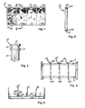
- sieve elements 10 are designed as rectangular plates, which are provided over their flat expansions with a plurality of sieve openings. Along their longitudinal edges, they are provided with recesses 11a and 11 b, which work together with the corresponding recesses 11 a and 11 b of adjacent sieve elements to form receptacles 11.
- the sieve elements 10 are assembled by laying them with their edges abutting each other on the support frame 1 In such a way that the recesses 11 a and 11 b come to lie above the heads of previously installed mounting pins 13. Then the sieve elements 10 are fixed in place by hitting them with a hammer above the heads 14 of the mounting pins 13. As a result, the elastic material of which the sieve elements 10 are made is elastically deformed; this allows the heads 14 to enter the receptacles 11, where they snap in place, behind a bead 12.
- a suitable tool is inserted into the joint between two, abutting sieve elements 10. With the help of this tool, the sieve elements 10 are then pried off the mounting heads 14 of the mounting pins 13 under elastic deformation of their material. Both assembly and disassembly are therefore as simple as could be imagined and can be accomplished with very simple tools.
- FIG. 3 shows an embodiment of a mounting pin according to the invention, which is made of steel; this pin is identified by the reference number 13.
- the mounting pin 13 also has a head 14, a groove 15 underneath the head, and a support shoulder 16 underneath the groove. Underneath the support shoulder 16, mounting pin 13 is designed as a cylinder 18 with a slot 17 over its entire length. This cylinder is welded to a support frame 1 for a sieve bed.
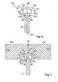
- mounting pin 13 of Figure 3 An alternate embodiment of the mounting pin 13 of Figure 3 is illustrated in Figures 6 and 7.
- the mounting pin of this alternative embodiment is identified by the reference numeral 30.
- Mounting pin 30 comprises a head 31 that is secured to a stem 32 having a slot 33 formed in its distal end.
- the head 31 of the mounting pin 30 has a frustoconical upper surface 31a, which forms an angle between 45° and 60° from the axis of symmetry 31e of the head 31.
- the top 31d of the head 31 is flat but may also be 31 a and 31b.
- Section 31c may be flat, i. e.cylindrical, or it may be radiused to form a gentle transition between head surfaces 31a and 31b.
- the configuration of the head 31 of mounting pin 30 is advantageous in that the amount of force necessary to insert the head 31 of the mounting pin 30 into the receptacle 41 formed between the sieve elements 40 is relatively low whereas the amount of force required to remove the sieve elements 40 from the support frame 1 is substantially higher and results in a stronger bond between the support frame 1 and the sieve element 40. This stronger bond in turn reduces the likelihood that a sieve element 40 will unnecessarily become dislodged from the support frame 1.
- the mounting pin 30 is fashioned of steel or another alloy that can easily be secured, as by welding, to the vertical ribs 19 that form the support frame 1 of this embodiment.
- other materials may be used in fashioning the head 31 of the mounting pin 30 so long as the head 31 remains substantially rigid.
- the head 31 of the mounting pin 30 may be coated or clad with a layer of a ceramic material, a plastic material such as Teflon, or even plated.
- the head 31 may be fashioned completely from a ceramic material and secured to the stem 32.
- the head 31 will be case hardened, as by carburizing, to increase the strength and abrasion resisting capabilities of the head 31.
- the stem 32 extends away from the head 31, preferably in a normal relationship to the head 31.
- the stem 31 is narrower in cross-section than the head 31 and has a slot 33 formed in the distal end of the stem 32 opposite the head 31 of the mounting pin 30.
- the slot 33 extends from the distal end of the stem 32 along the stem 32 in the direction of the head 31, thereby forming a pair of legs 33b.
- the slot 33 terminates in a shoulder 33a that is preferably formed in a perpendicular planar relationship with the axis of symmetry 31 c of the mounting pin 30.
- the slot 33 is sized to receive therein the upper edge of a vertical rib 19, with the legs of the stem 32 extending down each side of the rib 19.
- the flat shoulder 33a acts to properly orient the head 31 of the mounting pin above the upper edge of the vertical rib 19.
- the mounting pin 30 is secured to the rib 19 by welding only the distal ends of the logs 33b to the respective sides of the rib 19, though the welds could extend up the legs 33b if need be.
- the stem 32 and slot 33 are to be sufficiently long that the weld 36 will be spaced apart from the upper edge of the vertical rib 19 to an extent that will prevent the welds from deforming the upper edge of the rib 19 or damaging the hardened head 31 of the mounting pin 30. Sizing the stem 32 and slot 33 relatively long also advantageously allows a damaged mounting pin 30 to be cut or ground off of the rib 19 and replaced without damaging or deforming the upper surface of the rib 19.
- the mounting pin 30 is a unitary structure of a suitable steel. This allows the mounting pin 30 to be welded to a support frame.
- the head 31 and stem 32 may be fabricated from different materials.
- the stem may be fabricated from steel whereas the head 31 is a ceramic material joined to the stem 32 by an adhesive or by a mechanical fastener.
- the vertical ribs 19 have a width that is thinner than the maximum width of the mounting pins 30.
- the relatively thin vertical ribs 19 maximize the throughput of the sieve bed by reducing the resistance to flow, i. e., the ribs 19 do not block the flow of particulate materials through the sieve elements 40 of the sieve bed.
- the ribs 19 are typically arranged in a side by side arrangement over a sub-frame to form the support frame 1 to which the sieve elements 40 are secured. Though the ribs 19 are thin, their depth may be varied to increase or decrease the maximum load capacities of the sifting machine.
- the vertical ribs 19 are preferably installed so that their upper edges are coplanar with each other. This ensures that the upper surface of the sieve elements 40 will be substantially flat.
- the top edges of the vertical ribs are preferably flat and perpendicular to the sides of the rib 19 to properly position the mounting pins 30 thereon.
- the vertical ribs 19 are preferably welded to the sub-frame to form the support frame 1, but may also be bolted, screwed, or otherwise secured to the subframe of the sieve bed.
- the mounting pins 30 are secured to the upper edge of the vertical ribs 19 at between 5" (12,7 cm) and 14" (35,6 cm) on center.
- the vertical ribs 19 may be installed on a sub-frame to form the support frame 1 before the mounting pins 30 are secured to the ribs 19.
- these mounting pins 30 may be individually cut off and replaced, or the entire section of vertical rib 19 having the damaged mounting pins 30 thereon may be removed and replaced with another section of vertical rib 19 and mounting pins 30.
- the vertical rib 19 with the damaged mounting pins 30 may then be repaired at leisure without incurring large amounts of downtime for the sifting operation.
- Figure 7 illustrates adjacent and abutting sieve elements 40a and 40b held in place over the support frame 1 by a mounting pin 30 that is secured to a vertical rib 19 of support frame 1.
- the sieve elements 40a and 40b are provided on their abutting edges with corresponding recesses 41a and 41b which work together to form a receptacle 41 having a shape that is complimentary to the shape of the head 31 of the mounting pin 30.
- the head 31 of the mounting pin 30 is received in the receptacle 41 formed between the sieve elements 40a and 40b in an interlocking manner.
- the height of the receptacle 41 is to be no greater than the height of the head 31 of the mounting pin 30. Matching the heights of the receptacle 41 to the height of the head 31 of the mounting pin 30 results in a tight engagement between the receptacle 41 and the head of the mounting pin 30.
- the height of the receptacle 41 will be slightly smaller than that of the head 31 so as to create what can be described as a press-fit between the head of the mounting pin 30 and the receptacle 41.
- Receptacle 41 is closed off at its top and has an entrance or opening at its bottom so that the head 31 of the mounting pin 30 may be inserted into the receptade 41. It should be noted that the diameter of the opening of the receptacle 41 is smaller than that of the head 31. This smaller opening is formed by a circumferential bead 42 that consists of two bead sections 42a and 42b that project inwardly from the wall of the receptacle 41. The bead 42 of the receptacle 41 closely engages the undersurface 31 b of the head 31 to hold the sieve elements 40a and 40b in place upon the support frame 1.
- the frustoconical upper surface 31 a of the mounting pin 30 will deflect the bead 42, thereby allowing the head 31 of the pin 30 to enter.
- Increasing the angle of the upper surface 31a eases the entry of the head 31 into the receptacle 42 and conversely, flattening the angle of surface 31 a tends to make the insertion more difficult.
- angling the undersurface 31b of the head 31 upward will present a frustoconical surface to the entrance of the receptacle 41 and will ease the egress of the head 31 from the receptacle 41.
- the undersurface 31b perpendicular to the axis of symmetry 31e of the mounting pin 30 so as to increase the magnitude of the force required to remove the head 31 of the mounting pin from the receptacle 41.
- the sieve elements 40a and 40b are assembled by laying them with their respective edges abutting each other above the support frame 1 in such way that the recesses 41a and 41b come to lie above the heads 31 of the previously installed mounting pins 30.
- the sieve elements 40a and 40b are then fixed in place by forcing them down on to the mounting pins 30 as by striking them with a hammer.
- the material of which the sieve elements 40a and 40b are made do elastically deform to allow the heads 31 of the mounting pins 30 to enter the receptacles 41 which snap in place below the beveled undersurface 31 b of the mounting pins 30.
- a suitable tool is inserted into the joint between the two abutting sieve elements 40a, 40b, and with the help of this tool, the sieve elements 40a, 40b are then pried off the mounting heads 31 of the pins 30 under the elastic deformation of the material of the sieve elements 40a. 40b.
- the diameters of the mounting pins 30 are relatively small, very little useful area Is lost.
- the only useful area that is lost is due to the lands 44 that define the upper surface of the portion of the sieve element 40 where the receptacle 41 is located in the sieve element. See Figure 1.
- the diameter of the receptacle half 41 a or 41 b expressed on the upper surface of the sieve element 40 as lands 44 arc at most twice the diameter of the head 31 of the mounting pin 30 received within the receptacle 41.
- the small amount of lost surface area 44 results in the maximum amount of useful area for the sifting machine and hence, the maximum throughput for particulate materials.
- Another benefit to the small amount of lost surface area is that it is possible to utilize more mounting pins 30 in a given application, without needlessly sacrificing useful area.
- more mounting pins 30 may be used to secure the sieve elements 40 to the support frame 1, thereby decreasing the likelihood that a sieve element 40 may become dislodged during use.
- a sifting machine may be designed that maximizes both throughput of particulate materials and the weight capacity of the sifting machine without having to sacrifice the former for the latter.
- each sieve element 40 is also desirable to form a seal or lip 46 around the periphery of each sieve element 40 as illustrated in Figures 7 or 9.
- the respective seals 46 on abutting sieve elements 40 form a barrier to particulate materials and fines that might otherwise insinuate themselves into the joint between the respective panels or Into the receptacles 41 In which the heads 31 of the mounting pins 30 are received.
- the mounting pins' ability to secure the sieve panels 40 to the support frame 1 may be compromised, thereby resulting in the inadvertent dislodgement of a sieve panel. While this cannot in all instances be prevented by including a seal 46 at the edge of the panels, the likelihood of inadvertent dislodgement of a sieve panel can be greatly reduced.
- FIG. 8 Yet another embodiment of a mounting pin constructed and arranged according to the Budapests of the present invention is illustrated in Figures 8 and 9.
- Mounting pin 50 shown in Figure 8 is similar to mounting pin 30 illustrated in Figure 6.
- Mounting pin 50 omits the stem 32 of the mounting pin 30 and the lower beveled surface 31b of the head 31 of mounting pin 30.
- the mounting pin 50 is fabricated from steel using a stamping process.
- Mounting pin 50 has an upper frustoconical surface 51, which extends downwardly from a cylindrical body 52 at an angle of approximately 45°.
- a cylindrical bore or hole 53 is formed through the bottom of the cylindrical body 52.
- the mounting pin 50 is secured to the support structure 1 using well-known plug welding techniques.
- a mounting pin 50 is placed in a predetermined position and attitude in contact with the upper surface of the vertical member 19 of the support frame 1.
- a weld material 54 suitable for use with the material from which the mounting pin 50 fabricated is heated to melting and inserted into the hole 53. The molten weld material 54 fuses the mounting pin 50 to the upper surface of the vertical web 19 of the support frame 1.
- sieve elements 40A and 40B having recesses 41 A and 41 B as illustrated in Figure 7 With both mounting pins 30 and 50, it is possible to utilize sieve elements 40A and 40B having recesses 41 A and 41 B as illustrated in Figure 7 with both mounting pins 30 and 50. See Figure 9. Alternatively, sieve elements having recesses that correspond more closely to the profile of the mounting pin 50 may be provided. The sieve elements used in conjunction with mounting pin 50 are secured to and removed from the mounting pin 50 in the same manner as described above in connection with mounting pin 30.
Landscapes
- Engineering & Computer Science (AREA)
- General Engineering & Computer Science (AREA)
- Mechanical Engineering (AREA)
- Combined Means For Separation Of Solids (AREA)
- Component Parts Of Construction Machinery (AREA)
- Pharmaceuticals Containing Other Organic And Inorganic Compounds (AREA)
- Solid-Sorbent Or Filter-Aiding Compositions (AREA)
Claims (15)
- Tragrahmen für einen Siebboden, mit einer Mehrzahl von länglichen Stegen (19), deren Stärke jeweils wesentlich kleiner ist als deren Höhe, wobei die Stege (19) nebeneinander auf einem Unterbau angeordnet sind, so dass die Oberkanten der Stege (19) im Wesentlichen koplanar sind, wobei jeder Steg (19) außerdem eine Mehrzahl von im Wesentlichen starren Befestigungszapfen (30, 50) aufweist, die an der Oberkante jedes Steges (19) angeordnet sind, um an dem Tragrahmen eine Anzahl von Siebelementen (40) festzulegen, die aneinander grenzend nebeneinander angeordnet sind, wobei die Befestigungszapfen (30, 50) außerdem eine kegelstumpfförmige Oberseite (31a) haben, die so angeordnet und ausgelegt ist, dass sie in einen Aufnahmeraum (41) eingreift, der durch zusammenwirkende Ausnehmungen (41a, 41b) an den Kanten von aneinander grenzenden Siebelementen (40a, 40b) gebildet wird, wobei die Aufnahmeräume (41) für die Befestigungszapfen (30, 50) oben geschlossen sind,
dadurch gekennzeichnet, dass die Befestigungszapfen (30, 50) und die Stege (19) aus einer eisenhaltigen Legierung hergestellt sind, wobei die Befestigungszapfen (30, 50) an den Stegen (19) durch Schweißen befestigt sind. - Tragrahmen für einen Siebboden nach Anspruch 1, dadurch gekennzeichnet, dass die Befestigungszapfen (30) außerdem einen pilzförmigen Kopf (31) mit einer kegelstumpfförmigen Oberseite (31 a) und einer im Wesentlichen flachen Unterseite (31 b) aufweisen, wobei sich ein Schaft (32) von der Unterseite (31 b) des Kopfes (31) aus im Wesentlichen senkrecht zum Kopf (31) erstreckt, wobei in dem Schaft (32) ein Schlitz (33) ausgebildet ist, der sich vom Distalende des Schaftes (32) zum Kopf (31) hin erstreckt, wobei der Schlitz (33) so angeordnet und ausgelegt ist, dass darin die Oberkante eines Stegs (19) aufnehmbar ist, um den Befestigungszapfen (30) an dem Steg (19) zu fixieren.
- Tragrahmen für einen Siebboden nach Anspruch 2, dadurch gekennzeichnet, dass der Durchmesser des Kopfes (31) der Befestigungszapfen (30) größer ist als die Breite der Stege (19).
- Tragrahmen für einen Siebboden nach Anspruch 2, dadurch gekennzeichnet, dass der im Schaft (32) des Befestigungszapfens (30) ausgebildete Schlitz (33) in einer im Wesentlichen flachen Schulter (33a) endet, deren Ebene senkrecht zur Symmetrieachse (31 e) des Schafts (32) des Befestigungszapfens (30) ausgerichtet ist.
- Tragrahmen für einen Siebboden nach Anspruch 1, dadurch gekennzeichnet, dass der Befestigungszapfen (50) aus einer Metallplatte gestanzt ist und einen hohlzylindrischen Körper mit einer Oberseite und einer Unterseite (52) aufweist, wobei an der Unterseite (52) des Körpers eine durchgehende Öffnung (53) ausgebildet ist und wobei an der Oberseite eine von dem Körper herabhängende, im Wesentlichen kegelstumpfförmige Oberfläche (51) ausgebildet ist.
- Tragrahmen für einen Siebboden nach Anspruch 5, dadurch gekennzeichnet, dass der Befestigungszapfen (50) an der Oberkante eines Stegs (19) durch Verschweißen durch die Öffnung (53) des zylindrischen Körpers des Zapfens (50) befestigt ist.
- Siebmaschine mit einem Unterbau, einem Tragrahmen (1), der auf dem Unterbau aufliegt und an diesem befestigt ist, wobei der Tragrahmen (1) eine Mehrzahl von länglichen dünnen Stegen (19) aufweist, deren Oberkanten im Wesentlich koplanar angeordnet sind, wobei jeder der Stege (19) eine Mehrzahl von Befestigungszapfen (13) aufweist, wobei jeder Befestigungszapfen (13) einen pilzförmigen Kopf (14) mit einer kegelstumpfförmigen Oberseite und einen an der Unterseite des Kopfes (14) befestigten und sich vom Kopf (14) weg erstreckenden Schaft (18) aufweist, wobei in dem Distalende des Schafts (18) ein Schlitz (17) ausgebildet ist, der sich vom Distalende des Schafts (18) zum Kopf (14) erstreckt und bei einem vorbestimmten Abstand vom Kopf (14) endet, und wobei eine Anzahl von Siebelementen (10) aneinander grenzend nebeneinander an dem Tragrahmen (1) durch die Befestigungszapfen (13) befestigt sind, wobei der Kopf (14) jedes Befestigungszapfens in ein Paar aneinander grenzende Ausnehmungen (11a, 11b) eingreift, wobei jede Ausnehmung (11a, 11 b) in den jeweiligen Kanten von aneinander grenzenden Siebelementen (10a, 10b) ausgebildet ist und wobei das Paar aneinander grenzender Ausnehmungen (11a, 11 b) zusammenwirken und einen Aufnahmeraum (11) bilden, der komplementär zur Form des Kopfes (14) des Befestigungszapfens (13) ausgebildet ist, wobei der Aufnahmeraum (11) für den Kopf (14) des Befestigungszapfens (13) oben geschlossen ist,
dadurch gekennzeichnet, dass die Befestigungszapfen (13) auf den Stegen (19) sitzen, und zwar so, dass die Oberkanten der Stege (19) in den Schlitzen (17) der Befestigungszapfen (13) aufgenommen sind, wobei die Befestigungszapfen (13) und die Stege (19) aus einer eisenhaltigen Legierung hergestellt sind und wobei die Befestigungszapfen (13) an den Stegen (19) durch Schweißen befestigt sind. - Siebmaschine nach Anspruch 7, dadurch gekennzeichnet, dass die Ausnehmungen (11a, 11b), die in den Kanten der Siebelemente (10a, 10b) ausgebildet sind, eine vertikale Abmessung haben, die geringer ist als die vertikale Höhe des Kopfes (14) des Befestigungszapfens (13), so dass das Material der Siebelemente (10a, 10b), das die Ausnehmungen (11a, 11 b) umgibt, eine Kraft auf den Kopf (14) des Befestigungszapfens (13) ausübt, wenn der Kopf (14) des Befestigungszapfens (13) in den durch die Ausnehmungen (11 a, 11 b) gebildeten Aufnahmeraum (11) eingreift.
- Siebmaschine nach Anspruch 7, dadurch gekennzeichnet, dass die Köpfe (14) der Befestigungszapfen (13) außerdem an der Oberseite eine Oberfläche aufweisen, die nach außen und unten unter einem Winkel von ungefähr 45° ausgehend von einer Ebene senkrecht zur Symmetrieachse des Kopfes (14) des Befestigungszapfens (13) verlaufen, sowie eine Unterseite, die von einer Ebene senkrecht zur Symmetrieachse des Schafts des Befestigungszapfens aus unter einem Winkel von +5° bis -5° verläuft.
- Siebmaschine nach Anspruch 9, dadurch gekennzeichnet, dass der Befestigungszapfen (13) auf den Steg (19) aufgesetzt ist und an dem Steg befestigt ist, indem nur das Distalende des Schafts (18) mit den jeweiligen Seiten des Stegs (19) verschweißt ist.
- Siebmaschine nach Anspruch 7, dadurch gekennzeichnet, dass die Befestigungszapfen (13) entlang der jeweiligen Stege (19) mit einem Abstand der Mittelachsen von 12,7 cm bis 35,6 cm (5 bis 14 Zoll) angeordnet sind.
- Siebmaschine nach Anspruch 7, dadurch gekennzeichnet, dass die Fläche des Siebelements (10) unmittelbar angrenzend an jede in der Kante des Siebelements (10) ausgebildete Ausnehmung (11) im Wesentlichen frei von einer Perforation ist und einen Durchmesser hat, der kleiner ist als das Doppelte des Durchmessers des Kopfes (14) des Befestigungszapfens (13).
- Siebmaschine nach Anspruch 7, dadurch gekennzeichnet, dass die Siebelemente (10) außerdem einen entlang der seitlichen Kanten ausgebildeten Wulst aufweisen, so dass die Wulste der aneinander grenzenden Kanten der jeweiligen Siebelemente (10) sich gegenseitig berühren und zwischen sich eine Dichtung ausbilden, wenn die Siebelemente (10) aneinander grenzend nebeneinander eingebaut sind.
- Siebelement zum Sieben von Feststoffen mittels einer Siebmaschine nach Anspruch 7, mit einem Panel, das mehrere seitliche Kanten aufweist, die eine Siebfläche des Panels bilden, wobei in der Oberfläche des Panels eine Mehrzahl von Sieböffnungen vorgegebner Größe ausgebildet sind und wobei eine Mehrzahl von Aufnahmeöffnungen (11a, 11 b) in den seitlichen Kanten des Panels ausgebildet sind, die so ausgelegt und angeordnet sind, dass darin eine Einrichtung zur Befestigung des Siebelements (10) an einem Tragrahmen (1) einer Siebmaschine eingreifen kann, wobei die Aufnahmeöffnungen (11a, 11b) des Weiteren so ausgelegt und angeordnet sind, dass eine Teilfläche der Sieboberfläche im Bereich der jeweiligen Aufnahmeöffnung (11a, 11 b) einen Durchmesser hat, der weniger als zweimal so groß ist, wie der Durchmesser der Aufnahmeöffnung (11 a, 11 b) selbst.
- Siebelement nach Anspruch 14, gekennzeichnet durch einen Wulst (46), der entlang der seitlichen Kante des Siebelements (10, 40) ausgebildet ist, so dass die Wulste (46) an den aneinander grenzenden Kanten der jeweiligen Siebelemente (10, 40) sich gegenseitig berühren und so zwischen sich eine Dichtung ausbilden, um den Durchfluss von Feststoffen zu verhindern, wenn die Siebelemente (10, 40) aneinander grenzend nebeneinander mit einem oder mehreren weiteren Siebelementen (10, 40) angeordnet sind.
Applications Claiming Priority (3)
| Application Number | Priority Date | Filing Date | Title |
|---|---|---|---|
| DE19918824A DE19918824B4 (de) | 1999-04-26 | 1999-04-26 | Siebboden für eine Siebmaschine |
| DE19918824 | 1999-04-26 | ||
| PCT/US2000/011162 WO2000064599A2 (en) | 1999-04-26 | 2000-04-26 | Sieve bed for a sifting machine |
Publications (3)
| Publication Number | Publication Date |
|---|---|
| EP1303363A2 EP1303363A2 (de) | 2003-04-23 |
| EP1303363A4 EP1303363A4 (de) | 2004-06-02 |
| EP1303363B1 true EP1303363B1 (de) | 2007-02-14 |
Family
ID=7905849
Family Applications (1)
| Application Number | Title | Priority Date | Filing Date |
|---|---|---|---|
| EP00928394A Expired - Lifetime EP1303363B1 (de) | 1999-04-26 | 2000-04-26 | Siebbett für siebmaschine |
Country Status (7)
| Country | Link |
|---|---|
| EP (1) | EP1303363B1 (de) |
| AT (1) | ATE353714T1 (de) |
| AU (1) | AU4664300A (de) |
| CA (1) | CA2369321C (de) |
| DE (2) | DE19918824B4 (de) |
| MX (1) | MXPA01009785A (de) |
| WO (1) | WO2000064599A2 (de) |
Families Citing this family (5)
| Publication number | Priority date | Publication date | Assignee | Title |
|---|---|---|---|---|
| US6957741B2 (en) | 2001-08-07 | 2005-10-25 | Manfred Franz Axel Freissle | Screening arrangement |
| WO2003047771A1 (en) * | 2001-12-07 | 2003-06-12 | David Llewellyn Owen | Fastening means for screens |
| US7413087B2 (en) | 2002-02-11 | 2008-08-19 | Multotec Manufacturing (Pty) Limited | Screen deck |
| WO2006034526A1 (en) | 2004-09-27 | 2006-04-06 | Weatherford Australia Pty Limited | A screening module retaining member |
| DE102009051946A1 (de) * | 2009-11-04 | 2011-05-05 | Ludwig Krieger Draht- Und Kunststofferzeugnisse Gmbh | Siebmaschine |
Family Cites Families (13)
| Publication number | Priority date | Publication date | Assignee | Title |
|---|---|---|---|---|
| US2255939A (en) * | 1939-02-25 | 1941-09-16 | Gustave A Overstrom | Screen |
| ZA774472B (en) * | 1977-07-25 | 1979-06-27 | Herrmann Screens Mfg Co Ltd | Improvements in or relating to screening apparatus |
| DE7811183U1 (de) * | 1978-04-14 | 1978-07-27 | Gummi-Kueper Gmbh & Co Kg, 4630 Bochum | Siebboden |
| DE2926987B1 (de) * | 1979-07-04 | 1981-01-15 | Steinhaus Gmbh | Siebmaschinen-Siebdeck |
| DE3425485A1 (de) * | 1984-07-11 | 1986-01-16 | Hein, Lehmann AG, 4000 Düsseldorf | Siebbelag |
| DE3666365D1 (en) * | 1986-03-13 | 1989-11-23 | Hein Lehmann Ag | Screen bottom |
| DE3724246A1 (de) * | 1987-07-22 | 1989-02-02 | Wahl Verschleiss Tech | Verschleissfestes sieb |
| GB2210292B (en) * | 1987-09-26 | 1991-07-03 | Polydeck Screen Corp | Screening panels and screen decks |
| AU629881B2 (en) * | 1988-11-23 | 1992-10-15 | Western Wire Works, Incorporated | Modular system |
| DE4303892C2 (de) * | 1993-02-10 | 2001-07-12 | Ludwig Krieger Draht Und Kunst | Siebbelag |
| ZA94452B (en) * | 1993-06-23 | 1994-09-02 | Screenex Wire Weaving Mfg Ltd | Screening arrangement |
| US5361911A (en) * | 1994-04-14 | 1994-11-08 | Miller Wire Works, Inc. | Screening panel attachment system |
| AUPN514395A0 (en) * | 1995-08-31 | 1995-09-21 | Lettela Proprietary Limited | Screening apparatus |
-
1999
- 1999-04-26 DE DE19918824A patent/DE19918824B4/de not_active Expired - Lifetime
-
2000
- 2000-04-26 AT AT00928394T patent/ATE353714T1/de not_active IP Right Cessation
- 2000-04-26 DE DE60033446T patent/DE60033446T2/de not_active Expired - Lifetime
- 2000-04-26 EP EP00928394A patent/EP1303363B1/de not_active Expired - Lifetime
- 2000-04-26 WO PCT/US2000/011162 patent/WO2000064599A2/en not_active Ceased
- 2000-04-26 AU AU46643/00A patent/AU4664300A/en not_active Abandoned
- 2000-04-26 MX MXPA01009785A patent/MXPA01009785A/es active IP Right Grant
- 2000-04-26 CA CA002369321A patent/CA2369321C/en not_active Expired - Lifetime
Also Published As
| Publication number | Publication date |
|---|---|
| WO2000064599A3 (en) | 2003-02-06 |
| CA2369321A1 (en) | 2000-11-02 |
| EP1303363A4 (de) | 2004-06-02 |
| EP1303363A2 (de) | 2003-04-23 |
| AU4664300A (en) | 2000-11-10 |
| CA2369321C (en) | 2007-10-30 |
| MXPA01009785A (es) | 2003-06-24 |
| DE60033446T2 (de) | 2007-11-29 |
| DE19918824B4 (de) | 2005-12-22 |
| DE60033446D1 (de) | 2007-03-29 |
| DE19918824A1 (de) | 2000-11-02 |
| ATE353714T1 (de) | 2007-03-15 |
| WO2000064599A2 (en) | 2000-11-02 |
Similar Documents
| Publication | Publication Date | Title |
|---|---|---|
| US6634505B1 (en) | Sieve bed for a sifting machine | |
| CA2770877C (en) | Screen panel retainer system | |
| CA2333387C (en) | Device for the coupling of excavator teeth | |
| US7717269B2 (en) | Snap lock separatory panel and retainer system | |
| CA2794534C (en) | Locking twist pin screen panel retainer system | |
| US20020079279A1 (en) | Friction wedge for a railroad car truck having a replaceable wear member | |
| WO1997028906A1 (en) | Screen for vibrating separator | |
| EP0419585B1 (de) | Modulares system | |
| KR20150086498A (ko) | 스크린 패널용 스냅핏 고정 시스템 | |
| EP1303363B1 (de) | Siebbett für siebmaschine | |
| CN102947004A (zh) | 耐磨板系统、装置和方法 | |
| US5462175A (en) | Screen lining | |
| US7731035B2 (en) | Ore screening panel frame system | |
| US7225916B2 (en) | Belt cleaner | |
| US20050016902A1 (en) | Screening panel securing system | |
| US5724756A (en) | Bucket tip retention means | |
| US5823426A (en) | Railway plate and method of manufacture | |
| ZA200900466B (en) | Ore screening panel frame cover | |
| AU742060B2 (en) | Screening assembly | |
| US6872025B2 (en) | Toggle retainer for toggle connections | |
| CN116367932A (zh) | 筛选面板的改进 | |
| KR200344848Y1 (ko) | 쇄석 선별기의 쇄석 선별망 설치구조 | |
| AU4116099A (en) | Screen deck module | |
| AU770350B2 (en) | Modular screening system | |
| AU2006200441B2 (en) | Ore Screening Panel Frame System |
Legal Events
| Date | Code | Title | Description |
|---|---|---|---|
| PUAI | Public reference made under article 153(3) epc to a published international application that has entered the european phase |
Free format text: ORIGINAL CODE: 0009012 |
|
| 17P | Request for examination filed |
Effective date: 20011030 |
|
| AK | Designated contracting states |
Designated state(s): AT BE CH CY DE DK ES FI FR GB GR IE IT LI LU MC NL PT SE |
|
| A4 | Supplementary search report drawn up and despatched |
Effective date: 20040419 |
|
| RTI1 | Title (correction) |
Free format text: SIEVE BED FOR A SIFTING MACHINE |
|
| 17Q | First examination report despatched |
Effective date: 20050621 |
|
| GRAP | Despatch of communication of intention to grant a patent |
Free format text: ORIGINAL CODE: EPIDOSNIGR1 |
|
| GRAS | Grant fee paid |
Free format text: ORIGINAL CODE: EPIDOSNIGR3 |
|
| GRAA | (expected) grant |
Free format text: ORIGINAL CODE: 0009210 |
|
| AK | Designated contracting states |
Kind code of ref document: B1 Designated state(s): AT BE CH CY DE DK ES FI FR GB GR IE IT LI LU MC NL PT SE |
|
| PG25 | Lapsed in a contracting state [announced via postgrant information from national office to epo] |
Ref country code: NL Free format text: LAPSE BECAUSE OF FAILURE TO SUBMIT A TRANSLATION OF THE DESCRIPTION OR TO PAY THE FEE WITHIN THE PRESCRIBED TIME-LIMIT Effective date: 20070214 Ref country code: BE Free format text: LAPSE BECAUSE OF FAILURE TO SUBMIT A TRANSLATION OF THE DESCRIPTION OR TO PAY THE FEE WITHIN THE PRESCRIBED TIME-LIMIT Effective date: 20070214 Ref country code: FI Free format text: LAPSE BECAUSE OF FAILURE TO SUBMIT A TRANSLATION OF THE DESCRIPTION OR TO PAY THE FEE WITHIN THE PRESCRIBED TIME-LIMIT Effective date: 20070214 Ref country code: AT Free format text: LAPSE BECAUSE OF FAILURE TO SUBMIT A TRANSLATION OF THE DESCRIPTION OR TO PAY THE FEE WITHIN THE PRESCRIBED TIME-LIMIT Effective date: 20070214 Ref country code: LI Free format text: LAPSE BECAUSE OF FAILURE TO SUBMIT A TRANSLATION OF THE DESCRIPTION OR TO PAY THE FEE WITHIN THE PRESCRIBED TIME-LIMIT Effective date: 20070214 Ref country code: DK Free format text: LAPSE BECAUSE OF FAILURE TO SUBMIT A TRANSLATION OF THE DESCRIPTION OR TO PAY THE FEE WITHIN THE PRESCRIBED TIME-LIMIT Effective date: 20070214 Ref country code: CH Free format text: LAPSE BECAUSE OF FAILURE TO SUBMIT A TRANSLATION OF THE DESCRIPTION OR TO PAY THE FEE WITHIN THE PRESCRIBED TIME-LIMIT Effective date: 20070214 |
|
| REG | Reference to a national code |
Ref country code: GB Ref legal event code: FG4D |
|
| REG | Reference to a national code |
Ref country code: CH Ref legal event code: EP |
|
| REF | Corresponds to: |
Ref document number: 60033446 Country of ref document: DE Date of ref document: 20070329 Kind code of ref document: P |
|
| REG | Reference to a national code |
Ref country code: IE Ref legal event code: FG4D |
|
| PG25 | Lapsed in a contracting state [announced via postgrant information from national office to epo] |
Ref country code: SE Free format text: LAPSE BECAUSE OF FAILURE TO SUBMIT A TRANSLATION OF THE DESCRIPTION OR TO PAY THE FEE WITHIN THE PRESCRIBED TIME-LIMIT Effective date: 20070514 |
|
| PG25 | Lapsed in a contracting state [announced via postgrant information from national office to epo] |
Ref country code: ES Free format text: LAPSE BECAUSE OF FAILURE TO SUBMIT A TRANSLATION OF THE DESCRIPTION OR TO PAY THE FEE WITHIN THE PRESCRIBED TIME-LIMIT Effective date: 20070525 |
|
| PG25 | Lapsed in a contracting state [announced via postgrant information from national office to epo] |
Ref country code: PT Free format text: LAPSE BECAUSE OF FAILURE TO SUBMIT A TRANSLATION OF THE DESCRIPTION OR TO PAY THE FEE WITHIN THE PRESCRIBED TIME-LIMIT Effective date: 20070716 |
|
| NLV1 | Nl: lapsed or annulled due to failure to fulfill the requirements of art. 29p and 29m of the patents act | ||
| REG | Reference to a national code |
Ref country code: CH Ref legal event code: PL |
|
| EN | Fr: translation not filed | ||
| PLBE | No opposition filed within time limit |
Free format text: ORIGINAL CODE: 0009261 |
|
| STAA | Information on the status of an ep patent application or granted ep patent |
Free format text: STATUS: NO OPPOSITION FILED WITHIN TIME LIMIT |
|
| 26N | No opposition filed |
Effective date: 20071115 |
|
| GBPC | Gb: european patent ceased through non-payment of renewal fee |
Effective date: 20070514 |
|
| PG25 | Lapsed in a contracting state [announced via postgrant information from national office to epo] |
Ref country code: GR Free format text: LAPSE BECAUSE OF FAILURE TO SUBMIT A TRANSLATION OF THE DESCRIPTION OR TO PAY THE FEE WITHIN THE PRESCRIBED TIME-LIMIT Effective date: 20070515 Ref country code: IT Free format text: LAPSE BECAUSE OF FAILURE TO SUBMIT A TRANSLATION OF THE DESCRIPTION OR TO PAY THE FEE WITHIN THE PRESCRIBED TIME-LIMIT Effective date: 20070214 Ref country code: FR Free format text: LAPSE BECAUSE OF FAILURE TO SUBMIT A TRANSLATION OF THE DESCRIPTION OR TO PAY THE FEE WITHIN THE PRESCRIBED TIME-LIMIT Effective date: 20071005 |
|
| PG25 | Lapsed in a contracting state [announced via postgrant information from national office to epo] |
Ref country code: GB Free format text: LAPSE BECAUSE OF NON-PAYMENT OF DUE FEES Effective date: 20070514 Ref country code: IE Free format text: LAPSE BECAUSE OF NON-PAYMENT OF DUE FEES Effective date: 20070426 |
|
| PG25 | Lapsed in a contracting state [announced via postgrant information from national office to epo] |
Ref country code: FR Free format text: LAPSE BECAUSE OF FAILURE TO SUBMIT A TRANSLATION OF THE DESCRIPTION OR TO PAY THE FEE WITHIN THE PRESCRIBED TIME-LIMIT Effective date: 20070214 |
|
| PG25 | Lapsed in a contracting state [announced via postgrant information from national office to epo] |
Ref country code: MC Free format text: LAPSE BECAUSE OF NON-PAYMENT OF DUE FEES Effective date: 20070430 |
|
| PG25 | Lapsed in a contracting state [announced via postgrant information from national office to epo] |
Ref country code: CY Free format text: LAPSE BECAUSE OF FAILURE TO SUBMIT A TRANSLATION OF THE DESCRIPTION OR TO PAY THE FEE WITHIN THE PRESCRIBED TIME-LIMIT Effective date: 20070214 |
|
| PG25 | Lapsed in a contracting state [announced via postgrant information from national office to epo] |
Ref country code: LU Free format text: LAPSE BECAUSE OF NON-PAYMENT OF DUE FEES Effective date: 20070426 |
|
| PGFP | Annual fee paid to national office [announced via postgrant information from national office to epo] |
Ref country code: DE Payment date: 20141031 Year of fee payment: 15 |
|
| REG | Reference to a national code |
Ref country code: DE Ref legal event code: R119 Ref document number: 60033446 Country of ref document: DE |
|
| PG25 | Lapsed in a contracting state [announced via postgrant information from national office to epo] |
Ref country code: DE Free format text: LAPSE BECAUSE OF NON-PAYMENT OF DUE FEES Effective date: 20151103 |