EP1304202B1 - Heizschlauchlose Fertigung von 3-Faltenbälgen - Google Patents
Heizschlauchlose Fertigung von 3-Faltenbälgen Download PDFInfo
- Publication number
- EP1304202B1 EP1304202B1 EP02018672A EP02018672A EP1304202B1 EP 1304202 B1 EP1304202 B1 EP 1304202B1 EP 02018672 A EP02018672 A EP 02018672A EP 02018672 A EP02018672 A EP 02018672A EP 1304202 B1 EP1304202 B1 EP 1304202B1
- Authority
- EP
- European Patent Office
- Prior art keywords
- profiled
- mould
- shells
- blank
- half shell
- Prior art date
- Legal status (The legal status is an assumption and is not a legal conclusion. Google has not performed a legal analysis and makes no representation as to the accuracy of the status listed.)
- Expired - Lifetime
Links
- 238000004519 manufacturing process Methods 0.000 title claims description 9
- 230000033001 locomotion Effects 0.000 claims abstract description 7
- 238000007493 shaping process Methods 0.000 claims abstract description 7
- 230000001360 synchronised effect Effects 0.000 claims abstract description 5
- 238000000034 method Methods 0.000 claims description 8
- 238000007789 sealing Methods 0.000 claims description 5
- 239000011324 bead Substances 0.000 claims description 4
- 238000000465 moulding Methods 0.000 claims 1
- 238000004073 vulcanization Methods 0.000 description 13
- 239000007787 solid Substances 0.000 description 4
- 210000001061 forehead Anatomy 0.000 description 3
- 239000004744 fabric Substances 0.000 description 2
- 238000000071 blow moulding Methods 0.000 description 1
- 238000011161 development Methods 0.000 description 1
- 230000018109 developmental process Effects 0.000 description 1
- 238000010438 heat treatment Methods 0.000 description 1
- 239000000314 lubricant Substances 0.000 description 1
- 230000001681 protective effect Effects 0.000 description 1
- 230000003014 reinforcing effect Effects 0.000 description 1
- 230000000284 resting effect Effects 0.000 description 1
- 238000004804 winding Methods 0.000 description 1
Images


Classifications
-
- B—PERFORMING OPERATIONS; TRANSPORTING
- B29—WORKING OF PLASTICS; WORKING OF SUBSTANCES IN A PLASTIC STATE IN GENERAL
- B29D—PRODUCING PARTICULAR ARTICLES FROM PLASTICS OR FROM SUBSTANCES IN A PLASTIC STATE
- B29D22/00—Producing hollow articles
- B29D22/02—Inflatable articles
- B29D22/023—Air springs; Air bellows
-
- B—PERFORMING OPERATIONS; TRANSPORTING
- B29—WORKING OF PLASTICS; WORKING OF SUBSTANCES IN A PLASTIC STATE IN GENERAL
- B29C—SHAPING OR JOINING OF PLASTICS; SHAPING OF MATERIAL IN A PLASTIC STATE, NOT OTHERWISE PROVIDED FOR; AFTER-TREATMENT OF THE SHAPED PRODUCTS, e.g. REPAIRING
- B29C33/00—Moulds or cores; Details thereof or accessories therefor
- B29C33/0088—Multi-face stack moulds
-
- B—PERFORMING OPERATIONS; TRANSPORTING
- B29—WORKING OF PLASTICS; WORKING OF SUBSTANCES IN A PLASTIC STATE IN GENERAL
- B29C—SHAPING OR JOINING OF PLASTICS; SHAPING OF MATERIAL IN A PLASTIC STATE, NOT OTHERWISE PROVIDED FOR; AFTER-TREATMENT OF THE SHAPED PRODUCTS, e.g. REPAIRING
- B29C49/00—Blow-moulding, i.e. blowing a preform or parison to a desired shape within a mould; Apparatus therefor
- B29C49/42—Component parts, details or accessories; Auxiliary operations
- B29C49/4236—Drive means
-
- B—PERFORMING OPERATIONS; TRANSPORTING
- B29—WORKING OF PLASTICS; WORKING OF SUBSTANCES IN A PLASTIC STATE IN GENERAL
- B29C—SHAPING OR JOINING OF PLASTICS; SHAPING OF MATERIAL IN A PLASTIC STATE, NOT OTHERWISE PROVIDED FOR; AFTER-TREATMENT OF THE SHAPED PRODUCTS, e.g. REPAIRING
- B29C49/00—Blow-moulding, i.e. blowing a preform or parison to a desired shape within a mould; Apparatus therefor
- B29C49/42—Component parts, details or accessories; Auxiliary operations
- B29C49/56—Opening, closing or clamping means
- B29C49/5605—Hydraulically operated, i.e. closing or opening of the mould parts is done by hydraulic means
-
- F—MECHANICAL ENGINEERING; LIGHTING; HEATING; WEAPONS; BLASTING
- F16—ENGINEERING ELEMENTS AND UNITS; GENERAL MEASURES FOR PRODUCING AND MAINTAINING EFFECTIVE FUNCTIONING OF MACHINES OR INSTALLATIONS; THERMAL INSULATION IN GENERAL
- F16F—SPRINGS; SHOCK-ABSORBERS; MEANS FOR DAMPING VIBRATION
- F16F9/00—Springs, vibration-dampers, shock-absorbers, or similarly-constructed movement-dampers using a fluid or the equivalent as damping medium
- F16F9/02—Springs, vibration-dampers, shock-absorbers, or similarly-constructed movement-dampers using a fluid or the equivalent as damping medium using gas only or vacuum
- F16F9/04—Springs, vibration-dampers, shock-absorbers, or similarly-constructed movement-dampers using a fluid or the equivalent as damping medium using gas only or vacuum in a chamber with a flexible wall
- F16F9/0409—Springs, vibration-dampers, shock-absorbers, or similarly-constructed movement-dampers using a fluid or the equivalent as damping medium using gas only or vacuum in a chamber with a flexible wall characterised by the wall structure
-
- F—MECHANICAL ENGINEERING; LIGHTING; HEATING; WEAPONS; BLASTING
- F16—ENGINEERING ELEMENTS AND UNITS; GENERAL MEASURES FOR PRODUCING AND MAINTAINING EFFECTIVE FUNCTIONING OF MACHINES OR INSTALLATIONS; THERMAL INSULATION IN GENERAL
- F16F—SPRINGS; SHOCK-ABSORBERS; MEANS FOR DAMPING VIBRATION
- F16F9/00—Springs, vibration-dampers, shock-absorbers, or similarly-constructed movement-dampers using a fluid or the equivalent as damping medium
- F16F9/02—Springs, vibration-dampers, shock-absorbers, or similarly-constructed movement-dampers using a fluid or the equivalent as damping medium using gas only or vacuum
- F16F9/04—Springs, vibration-dampers, shock-absorbers, or similarly-constructed movement-dampers using a fluid or the equivalent as damping medium using gas only or vacuum in a chamber with a flexible wall
- F16F9/0445—Springs, vibration-dampers, shock-absorbers, or similarly-constructed movement-dampers using a fluid or the equivalent as damping medium using gas only or vacuum in a chamber with a flexible wall characterised by intermediate rings or other not embedded reinforcing elements
-
- B—PERFORMING OPERATIONS; TRANSPORTING
- B29—WORKING OF PLASTICS; WORKING OF SUBSTANCES IN A PLASTIC STATE IN GENERAL
- B29C—SHAPING OR JOINING OF PLASTICS; SHAPING OF MATERIAL IN A PLASTIC STATE, NOT OTHERWISE PROVIDED FOR; AFTER-TREATMENT OF THE SHAPED PRODUCTS, e.g. REPAIRING
- B29C2949/00—Indexing scheme relating to blow-moulding
- B29C2949/07—Preforms or parisons characterised by their configuration
- B29C2949/079—Auxiliary parts or inserts
- B29C2949/08—Preforms made of several individual parts, e.g. by welding or gluing parts together
-
- B—PERFORMING OPERATIONS; TRANSPORTING
- B29—WORKING OF PLASTICS; WORKING OF SUBSTANCES IN A PLASTIC STATE IN GENERAL
- B29C—SHAPING OR JOINING OF PLASTICS; SHAPING OF MATERIAL IN A PLASTIC STATE, NOT OTHERWISE PROVIDED FOR; AFTER-TREATMENT OF THE SHAPED PRODUCTS, e.g. REPAIRING
- B29C35/00—Heating, cooling or curing, e.g. crosslinking or vulcanising; Apparatus therefor
- B29C35/02—Heating or curing, e.g. crosslinking or vulcanizing during moulding, e.g. in a mould
-
- B—PERFORMING OPERATIONS; TRANSPORTING
- B29—WORKING OF PLASTICS; WORKING OF SUBSTANCES IN A PLASTIC STATE IN GENERAL
- B29K—INDEXING SCHEME ASSOCIATED WITH SUBCLASSES B29B, B29C OR B29D, RELATING TO MOULDING MATERIALS OR TO MATERIALS FOR MOULDS, REINFORCEMENTS, FILLERS OR PREFORMED PARTS, e.g. INSERTS
- B29K2105/00—Condition, form or state of moulded material or of the material to be shaped
- B29K2105/25—Solid
- B29K2105/253—Preform
- B29K2105/258—Tubular
-
- B—PERFORMING OPERATIONS; TRANSPORTING
- B29—WORKING OF PLASTICS; WORKING OF SUBSTANCES IN A PLASTIC STATE IN GENERAL
- B29L—INDEXING SCHEME ASSOCIATED WITH SUBCLASS B29C, RELATING TO PARTICULAR ARTICLES
- B29L2031/00—Other particular articles
- B29L2031/703—Bellows
-
- B—PERFORMING OPERATIONS; TRANSPORTING
- B29—WORKING OF PLASTICS; WORKING OF SUBSTANCES IN A PLASTIC STATE IN GENERAL
- B29L—INDEXING SCHEME ASSOCIATED WITH SUBCLASS B29C, RELATING TO PARTICULAR ARTICLES
- B29L2031/00—Other particular articles
- B29L2031/721—Vibration dampening equipment, e.g. shock absorbers
Definitions
- the invention relates to a method for heating tubeless production of bellows made of cylindrical, not preformed blanks - according to the preamble of claim 1
- Air spring 2 bellows and their manufacture have long been known (see, for example, US Pat. Nos. 2,221,470, 2,814,072 and 4,749,345).
- a vulcanization mold for the production of 2-bellows for air springs usually consists of three segments, namely two end and a middle segment. These three segments are initially spaced apart and must be merged during the vulcanization process. The middle segment remains at rest. Only the two outer segments are moved synchronously towards the middle segment.
- the US 5,851,476, Figures 1 and 2 shows a manufacturable in the blow molding, pleated sealing sleeve.
- the shape of the relevant manufacturing device consists of two mutually mirror-symmetrical halves (FIG. 12), namely an upper and a lower half.
- the mold consists of an end outer profile solid shell (252 and 262), which in turn consists of an upper (Fig. 12) and a lower profile half shell, and between a plurality of middle inner profile solid shells (250, 248, 246 , 242 and 240), which in turn each consist of an upper and a lower profile half-shell (Fig. 12).
- the profile segments can be moved towards each other with the help of a kind of safety gate.
- the object of the invention is to produce a bellows with more than two folds.
- Preferred process steps for producing a 3-bellows are mentioned in claim 2.
- Embodiments and further developments of a device for carrying out the method will become apparent from claim 3 and from the further subclaims.
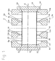
- the inventive (vulcanization) mold 2 for producing a 3-bellows 4 (Fig. 5) is divided by a guided through the longitudinal axis 6 horizontal plane in two mirror images of each other or mirror images of each other arranged halves and although in an upper 2a and in a lower half 2b.
- Each of these two halves 2a, 2b in turn consists of several segments, namely at both ends of each one end (outer) profile half-shell 8a, 8b; 10a, 10b and between them two middle (inner) profile half-shells 12a, 12b; 14a, 14b.
- An upper 8a and a lower end-side half-shell 8b together form a solid shell 8 (FIG. 3) which has a concave inner surface on its inner side.
- the profiling mold area is formed by longitudinally-centrally divided profile shells 8, 10, 12, 14.
- the profile segments 8a, 8b, 10a, 10b, 12a, 12b, 14a, 14b are axially guided in an upper and a lower base frame (not shown) and are actuated by hydraulic cylinders (not shown) mounted on the base frame on the front side.
- the base frame, profile shells 8, 10, 12, 14 and arranged on both sides Stirntellern 16, 18 existing form 2 is installed in a vertically closing press (not shown), wherein the profile or product axis 6 is horizontal.
- Fig. 1 shows a blank 20 which is axially between the segments 8a, 8b; 10a, 10b; 12a, 12b; 14a, 14b of the vulcanization mold 2 is arranged.
- the blank 20 may be provided at its ends with beads 22, 24.
- the blank 20 In the area of the middle (inner) profile half-shells 12a / 12b; 14a / 14b, the blank 20 each have a wire belt 26, 28, while the middle (inner) profile half-shells 12a / 12b; 14a / 14b each have a corresponding wire belt contour 30, 32.
- the blanks 20 are brought without additional operation by a winding drum (not shown) in the mold 2.
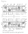
- the upper 8a, 10a, 12a, 14a and the lower profile segments 8b, 10b, 12b 14b are respectively via racks 40a, 46a, 48a, 54a; 40b, 46b, 48b, 54b and gears 42a, 44a, 50a, 52a; 42b, 44b, 50b, 52b together with additional sprockets 42a '50a'; 42b ', 50b' in operative connection with each other (Fig. 4a, Fig. 4b).
- the rack 40a which is located with a on the first middle (inner) profile half-shell 12a gear 42a and with a on the other end (profile) half-shell profile 10a located gear 44a in Intervention is.
- the gear 42a located on the central (inner) profile half-shell 12a has a second sprocket 42a 'with half the number of teeth.
- This ring gear 42a ' is engaged with a rack 46a fixed to the second middle (inner) profile half shell 14a.
- toothed rack 48a fastened to the second (upper) end-side (outer) profile half-shell 10a, which has a toothed wheel 50a located on the second central (inner) profile half-shell 14a and one end (outer) on the first Profile half shell 8a located gear 52a is engaged.
- the gear 50a located on the second middle (inner) profile half-shell 14a has a second gear 50a 'with half the number of teeth.
- This sprocket 50a ' is engaged with a rack 54a fixed to the first middle (inner) profile half shell 12a.
- the lower profile segments 8b, 10b, 12b and 14b have synchronous links compared to the upper links.
- a rack 40b is located on one (lower) end-side (outer) profile half-shell 8b, which has a toothed wheel 42b located on the first lower central (inner) profile half-shell 12b and an end (outer) profile on the other.
- Half shell 10b located gear 44b is engaged.
- the gear 42b located on the middle (inner) profile half-shell 12b has a second sprocket 42b 'with half the number of teeth. This sprocket 42b 'engages with a rack 46b located on the second middle (inner) profile half shell 14b.
- toothed rack 48b fastened to the second (lower) end-side (outer) profile half-shell 10b, which has a toothed wheel 50b located on the second central (inner) profile half-shell 14b and with one on the first end-side (outer) Profile half shell 8b located gear 52b is engaged.
- the gearwheel 50b located on the second middle (inner) profile half-shell 14b has a second gearwheel 50b 'with half the number of teeth.
- This sprocket 50b ' is engaged with a rack 54b fixed to the first middle (inner) profile half shell 12b.
- the ends of the blank 20 are first clamped on both end faces sealing and shaping each of a front plate 16, 18.
- the front plates 16, 18 drive the profile shells 8, 10, 12, 14 together under simultaneous pressure of the bombing so that the outer profile shells 8, 10 travel twice as well as the inner profile shells 12, 14.
- the shaping of the blank 20 via the bombing pressure is completed when the mold 2 has reached the closed position. The vulcanization process can be initiated.
- the 3 bellows press is in the open position.
- the mold 2 is opened vertically.
- the front plates 16, 18 of the mold 2 are about the two hydraulic cylinders in the open position (light measure between the open end plates 16, 18 approximately blank length plus 20 mm).
- the side parts of the mold 2 are moved over a distance limit to be set (approximately half the opening stroke) congruent in the upper 2a and lower part 2b apart.
- the blank 20 is inserted into the opened lower half 2b.
- the inner cones of the forehead plates 16, 18 dive into the blank 20 approximately 10 mm on each side and center it on the front side.
- the mold center parts 12, 14 receive the inserted cores 26, 28 of the blank 20.
- the forehead plates 16, 18 are driven to blank length.
- the press moves so that the mold 2 is closed vertically, but on the mold parting surfaces no closing pressure of the press.
- the front plates 16, 18 move, actuated via the coupled hydraulic cylinder, against the mold side parts 8, 10 and clamp the respective blank bead 22 and 24 shaping and sealing a. Under simultaneous bombing pressure in the blank 20, the two large hydraulic cylinders move the mold 2 axially into the closed position.
- the collapse of the mold side 8, 10 and middle parts 12, 14 takes place synchronously via a rack control, wherein the outer side parts 8, 10 cover twice the way as the middle parts 12, 14.
- the position of the two center part spacings be identical to the distance of the two inner cores 26, 28 of the blank 20.
- the shaping of the blank 20 via the bombing pressure is completed when the mold 2 has reached the closed position.
- the vulcanization process can be initiated.
- the forehead plates 16, 18 drive up first, then go the Formhibi- 8, 10 and -Mittelmaschine 12, 14 about 10 mm apart to release the article in the mold 2, only then opens the press.
- the articles can now be taken. Only after removal of the articles, the mold side parts are moved to the position described under I).
- the mold shells are guided on the running surfaces of the mold frame via guide elements with dry running properties. These guide surfaces must not come into contact with lubricant.
Landscapes
- Engineering & Computer Science (AREA)
- Mechanical Engineering (AREA)
- General Engineering & Computer Science (AREA)
- Manufacturing & Machinery (AREA)
- Heating, Cooling, Or Curing Plastics Or The Like In General (AREA)
- Shaping Metal By Deep-Drawing, Or The Like (AREA)
- Casting Or Compression Moulding Of Plastics Or The Like (AREA)
- Moulds For Moulding Plastics Or The Like (AREA)
- Resistance Heating (AREA)
- Thermotherapy And Cooling Therapy Devices (AREA)
- Shaping Of Tube Ends By Bending Or Straightening (AREA)
- Diaphragms And Bellows (AREA)
- Carbon And Carbon Compounds (AREA)
Description
- Die Erfindung betrifft ein Verfahren zur heizschlauchlosen Fertigung von Faltenbälgen aus zylindrischen, nicht vorgeformten Rohlingen - gemäß dem Oberbegriff des Anspruchs 1
- Luftfeder-2-Faltenbälge und deren Herstellung sind seit langem bekannt (siehe z. B. US 2,221,470; US 2,814,072 und US 4,749,345).
- Eine Vulkanisationsform zur Fertigung von 2-Faltenbälgen für Luftfedern besteht üblicherweise aus drei Segmenten, nämlich aus zwei endseitigen und einem mittleren Segment. Diese drei Segmente sind zunächst voneinander beabstandet und müssen im Laufe des Vulkanisationsprozesses zusammengefahren werden. Dabei bleibt das mittlere Segment in Ruhe. Lediglich die beiden äußeren Segmente werden synchron auf das mittlere Segment zu bewegt.
- Für die Fertigung von 3-Faltenbälgen benötigt man zwischen zwei endseitigen Segmenten zwei innere Segmente. Ein in Ruhe befindliches mittleres Segment gibt es nicht. Ein synchrones Zusammenfahren der vier Segmente ist nicht ohne weiteres möglich, da die einzelnen Segmente mit unterschiedlichen Geschwindigkeiten bewegt werden müssen.
- Die US 5,851,476, Fig.1 und 2, zeigt eine im Blasformverfahren herstellbare, gefältete Dichtmanschette. Die Form der diesbezüglichen Herstellvorrichtung besteht aus zwei spiegelbildlich zueinander ausgebildeten Hälften (Fig. 12), und zwar einer oberen und einer unteren Hälfte. Weiterhin besteht die Form aus einer endseitigen äußeren Profil-Vollschale (252 und 262), die wiederum jeweils aus einer oberen (Fig. 12) und einer unteren Profil-Halbschale besteht, und dazwischen mehreren mittleren inneren Profil-Vollschalen (250, 248, 246, 242 und 240), die wiederum jeweils aus einer oberen und einer unteren Profil-Halbschale bestehen (Fig. 12). Die Profilsegmente können mit Hilfe einer Art Scherengitter aufeinander zu bewegt werden.
Die Stabilität dieses Scherengitters scheint größeren Kräften, wie sie für die Herstellung von Luftfeder-Faltenbälgen erforderlich sind, kaum gewachsen zu sein. Insgesamt ist zu bezweifeln, dass auf diese Weise ein präzise reproduzierbares Ergebnis erzielt werden kann. Da der herzustellende Balg lediglich ein Schutzbalg ist, der keinen größeren Kräften ausgesetzt ist, ist es nicht verwunderlich, dass über die Länge des Balgs keinerlei Verstärkungseinlagen vorgesehen sind und somit auch die Profilsegmente diesbezüglich keinerlei Konturen aufweisen. - Die Aufgabe der Erfindung, wie sie mit Anspruch 1 erstmals gelöst ist, besteht darin, einen Faltenbalg mit mehr als zwei Falten zu fertigen.
Bevorzugte Verfahrensschritte zur Herstellung eines 3-Faltenbalges sind in Anspruch 2 genannt. Ausfiihrungsformen und apparative Weiterbildungen einer Vorrichtung zur Durchführung des Verfahrens ergeben sich aus dem Anspruch 3 und aus den weiteren Unteransprüchen. - Die Erfindung wird anhand eines Ausführungsbeispiels der Vulkanisationsform näher beschrieben. Es zeigt:
- Fig. 1 die Prinzipdarstellung des Längsschnitts durch eine erfindungsgemäße Vulkanisationsform mit Rohling;
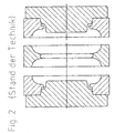
- Fig. 2 die Prinzipdarstellung des Längsschnitts durch eine herkömmliche Vulkanisationsform zur Herstellung eines 2-Faltenbalgs;
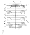
- Fig. 3 die Prinzipdarstellung des Längsschnitts durch eine erfindungsgemäße Vulkanisationsform mit geschlossenen Formschalen;
- Fig. 4 die Prinzipdarstellung des Längsschnitts durch eine Vulkanisationsform mit Darstellung der erfindungsgemäßen Zahnstangen-Steuerung; und zwar:
- Fig. 4a vertikal geöffnet, horizontal auseinandergefahren;
- Fig. 4b vertikal geschlossen, horizontal auseinandergefahren, und
- Fig. 5 einen ausgeformten 3-Faltenbalg im Längsschnitt.
- Wie in Fig. 1 dargestellt, ist die erfindungsgemäße (Vulkanisations-)Form 2 zur Herstellung eines 3-Faltenbalgs 4 (Fig. 5) durch eine durch die Längsachse 6 geführte horizontale Ebene in zwei spiegelbildlich zueinander ausgebildete bzw. spiegelbildlich zueinander angeordnete Hälften geteilt und zwar in eine obere 2a und in eine untere Hälfte 2b.
- Jede dieser beiden Hälften 2a, 2b besteht wiederum aus mehreren Segmenten, nämlich beidendig jeweils einer endseitigen (äußeren) Profil-Halbschale 8a, 8b; 10a, 10b und dazwischen zwei mittleren (inneren) Profil-Halbschalen 12a, 12b; 14a, 14b.
- Eine obere 8a und eine untere endseitige Halbschale 8b bilden zusammen eine Vollschale 8 (Fig. 3), die an ihrer Innenseite eine konkave Innenfläche aufweist. Dasselbe gilt für die andere obere 10a und untere endseitige Halbschale 10b. Auch diese bilden zusammen eine Vollschale 10, die ebenfalls eine konkave Innenfläche aufweist.
- Jede obere mittlere (innere) Profil-Halbschale 12a bzw. 14a bildet mit der jeweils zugehörigen unteren mittleren (inneren) Profil-Halbschale 12b bzw. 14b zusammen eine mittlere (innere) Profil-Vollschale 12 bzw. 14, die jeweils beidseitig konkav, d. h. bikonkav ausgebildet sind.
- D. h.: Der profilgebende Formenbereich wird durch längs-mittiggeteilte Profilschalen 8, 10, 12, 14 gebildet. Die Profil-Segmente 8a, 8b, 10a, 10b, 12a, 12b, 14a, 14b werden in einem oberen und einem unteren Grundgestell (nicht dargestellt) axial geführt und sind durch stirnseitig am Grundgestell montierte Hydraulikzylinder (nicht dargestellt) zu betätigen.
- Die aus Grundgestell, Profilschalen 8, 10, 12, 14 und beidseitig angeordneten Stirntellern 16, 18 bestehende Form 2 wird in eine sich vertikal schließende Presse (nicht dargestellt) eingebaut, wobei die Profil- bzw. Produktachse 6 horizontal liegt.
- Weiterhin zeigt die Fig. 1 einen Rohling 20, der axial zwischen den Segmenten 8a, 8b; 10a, 10b; 12a, 12b; 14a, 14b der Vulkanisationsform 2 angeordnet ist. Der Rohling 20 kann an seinen Enden mit Wülsten 22, 24 versehen sein. Im Bereich der mittleren (inneren) Profilhalbschalen 12a/12b; 14a/14b weist der Rohling 20 jeweils einen Drahtgürtel 26, 28 auf, während die mittleren (inneren) Profil-Halbschalen 12a/12b; 14a/14b jeweils eine entsprechende Drahtgürtelkontur 30, 32 aufweisen.
- Bei aus solchen Rohlingen 20 herzustellenden 3-Faltenbälgen 4, die zwischen den Falten 34, 36, 38 (Fig. 5) einvulkanisierte Drahtgürtel 26, 28 aufweisen, ist es erforderlich, dass im geöffneten, horizontal auseindergefahrenen Zustand der Form 2 der Abstand zwischen den Drahtgürtelkonturen 30, 32 der Profilschalen 12, 14 identisch ist mit dem Abstand zwischen den auf dem Rohling 20 angeordneten Drahtgürtelkernen 26, 28.
- Die Rohlinge 20 werden ohne zusätzlichen Arbeitsgang von einer Wickeltrommel (nicht dargestellt) in die Form 2 gebracht. Die Verformung des Rohlings 20 in die Faltenkontur, und damit auch die Veränderungen der Gewebewinkel der einzelnen Gewebelagen, erfolgt gleichmäßig.
- Die oberen 8a, 10a, 12a, 14a und die unteren Profilsegmente 8b, 10b, 12b 14b stehen jeweils über Zahnstangen 40a, 46a, 48a, 54a; 40b, 46b, 48b, 54b und Zahnräder 42a, 44a, 50a, 52a; 42b, 44b, 50b, 52b nebst zusätzlichen Zahnkränzen 42a' 50a'; 42b', 50b' miteinander in Wirkverbindung (Fig. 4a, Fig. 4b). Und zwar befindet sich an der einen (oberen) endseitigen (äußeren) Profil-Halbschale 8a die Zahnstange 40a, die mit einem auf der ersten mittleren (inneren) Profil-Halbschale 12a befindlichen Zahnrad 42a und mit einem auf der anderen endseitigen (äußeren) Profil-Halbschale 10a befindlichen Zahnrad 44a in Eingriff steht.
- Das auf der einen mittleren (inneren) Profil-Halbschale 12a befindliche Zahnrad 42a weist einen zweiten Zahnkranz 42a' mit halber Anzahl von Zähnen auf. Dieser Zahnkranz 42a' steht mit einer an der zweiten mittleren (inneren) Profil-Halbschale 14a befestigten Zahnstange 46a in Eingriff.
- Des weiteren gibt es eine an der zweiten (oberen) endseitigen (äußeren) Profil-Halbschale 10a befestigte Zahnstange 48a, die mit einem auf der zweiten mittleren (inneren) Profil-Halbschale 14a befindlichen Zahnrad 50a und mit einem auf der ersten endseitigen (äußeren) Profil-Halbschale 8a befindlichen Zahnrad 52a in Eingriff steht.
- Das auf der zweiten mittleren (inneren) Profil-Halbschale 14a befindliche Zahnrad 50a weist einen zweiten Zahnkranz 50a' mit halber Anzahl von Zähnen auf. Dieser Zahnkranz 50a' steht mit einer an der ersten mittleren (inneren) Profil-Halbschale 12a befestigten Zahnstange 54a in Eingriff.
- Bei den unteren Profil-Segmenten 8b, 10b, 12b und 14b gibt es - verglichen mit den oberen Verknüpfungen - synchrone Verknüpfungen.
- Auch hier befinden sich an der einen (unteren) endseitigen (äußeren) Profilhalbschale 8b eine Zahnstange 40b, die mit einem auf der ersten unteren mittleren (inneren) Profil-Halbschale 12b befindlichen Zahnrad 42b und mit einem auf der anderen endseitigen (äußeren) Profil-Halbschale 10b befindlichen Zahnrad 44b in Eingriff steht.
- Das auf der einen mittleren (inneren) Profil-Halbschale 12b befindliche Zahnrad 42b weist einen zweiten Zahnkranz 42b' mit halber Anzahl von Zähnen auf. Dieser Zahnkranz 42b' steht mit einer an der zweiten mittleren (inneren) Profil-Halbschale 14b befindlichen Zahnstange 46b in Eingriff.
- Darüber hinaus gibt es eine an der zweiten (unteren) endseitigen (äußeren) Profil-Halbschale 10b befestigte Zahnstange 48b, die mit einem auf der zweiten mittleren (inneren) Profil-Halbschale 14b befindlichen Zahnrad 50b und mit einem auf der ersten endseitigen (äußeren) Profil-Halbschale 8b befindlichen Zahnrad 52b in Eingriff steht.
- Auch hier weist das auf der zweiten mittleren (inneren) Profil-Halbschale 14b befindliche Zahnrad 50b einen zweiten Zahnkranz 50b' mit halber Anzahl von Zähnen auf. Dieser Zahnkranz 50b' steht mit einer an der ersten mittleren (inneren) Profil-Halbschale 12b befestigten Zahnstange 54b in Eingriff.
- Anstelle des Vortriebs mit Zahnstange und Zahnrad kann auch ein vergleichbarer anderer linearer mechanischer, elektromechanischer oder pneumatischer Vortrieb zum Einsatz gelangen.
- Durch gesteuerte Bewegungsabläufe, die durch Zahnstangensteuerungen synchron von beiden Stirnseiten erfolgt, werden die Enden des Rohlings 20 zunächst auf beiden Stirnseiten dichtend und formgebend jeweils an einen Stirnteller 16, 18 geklemmt. Im weiteren Bewegungsablauf fahren die Stirnteller 16, 18 die Profilschalen 8, 10, 12, 14 unter gleichzeitigem Bombagedruck so zusammen, dass die äußeren Profilschalen 8, 10 den doppelte Weg wie die inneren Profilschalen 12, 14 zurücklegen. Die Ausformung des Rohlings 20 über den Bombagedruck ist abgeschlossen, wenn die Form 2 die Schließstellung erreicht hat. Der Vulkanisationsvorgang kann eingeleitet werden.
- Die 3-Faltenbalgpresse befindet sich in geöffneter Stellung. Dabei ist die Form 2 vertikal geöffnet. Die Stirnteller 16, 18 der Form 2 sind über die beiden Hydraulikzylinder in geöffneter Stellung (lichtes Maß zwischen den geöffneten Stirntellern 16, 18 ca. Rohlingslänge plus 20 mm). Die Seitenteile der Form 2 sind über eine einzustellende Wegbegrenzung (ca. der halbe Öffnungshub) deckungsgleich im Ober- 2a und Unterteil 2b auseinander gefahren.
- Der Rohling 20 wird in die geöffnete Unterhälfte 2b eingelegt. Dabei tauchen die Innenkonen der Stirnteller 16, 18 ca. 10 mm je Seite in den Rohling 20 ein und zentrieren ihn stirnseitig vor. Die Formenmittelteile 12, 14 nehmen die eingelegten Kerne 26, 28 des Rohlings 20 auf. Die Stirnteller 16, 18 werden auf Rohlingslänge gefahren. Die Presse fährt so zu, dass die Form 2 zwar vertikal geschlossen ist, aber auf den Formenteilungsflächen kein Schließdruck der Presse ist. Die Stirnteller 16, 18 fahren, betätigt über die angekoppelten Hydraulikzylinder, gegen die Formenseitenteile 8, 10 und klemmen dabei den jeweiligen Rohlingswulst 22 bzw. 24 formgebend und dichtend ein. Unter gleichzeitigem Bombagedruck im Rohling 20 fahren die beiden großen Hydraulikzylinder die Form 2 axial in die Schließstellung. Das Zusammenfahren der Formen-Seiten- 8, 10 und -Mittelteile 12, 14 erfolgt synchron über eine Zahnstangensteuerung, wobei die äußeren Seitenteile 8, 10 den doppelten Weg zurücklegen wie die Mittelteile 12, 14. In der axialen Öffnungsstellung muss die Position der beiden Mittelteilabstände identisch mit dem Abstand der beiden inneren Kerne 26, 28 des Rohlings 20 sein.
- Die Ausformung des Rohlings 20 über den Bombagedruck ist abgeschlossen, wenn die Form 2 die Schließstellung erreicht hat. Der Vulkanisationsvorgang kann eingeleitet werden.
- Nach Beendigung des Vulkanisationsvorgangs müssen beim Öffnen der Form 2 zunächst die Stirnteller 16, 18 auffahren, danach fahren die Formseiten- 8, 10 und -Mittelteile 12, 14 ca. 10 mm auseinander, um den Artikel in der Form 2 zu lösen, erst dann öffnet die Presse. Die Artikel können nun entnommen werden. Erst nach Entnahmen der Artikel werden die Formenseitenteile in die unter I) beschriebene Stellung gefahren. Die Formenschalen werden auf den Laufflächen des Formengestells über Führungselemente mit Trockenlaufeigenschaften geführt. Diese Führungsflächen dürfen nicht mit Schmiermittel in Verbindung kommen.
-
- 2
- (Vulkanisations-)Form
- 2a, 2b
- spiegelbildlich ausgebildete Hälften der Form
- 2a
- Oberteil der Form, obere Hälfte
- 2b
- Unterteil der Form, untere Hälfte
- 4
- 3-Faltenbalg
- 6
- Längsachse der Form, Profil- und Produktachse
- 8a, 8b, 10a, 10b, 12a, 12b, 14a, 14b
- (Profil-)Segmente
- 8a, 8b; 10a, 10b
- endseitige (äußere) Profil-Halbschale
- 8, 10
- endseitige (äußere) Profil-Vollschale
- 12a, 12b; 14a, 14b
- mittlere (innere) Profil-Halbschale
- 12; 14
- mittlere (innere) Profil-Vollschale
- 16, 18
- Stirnteller
- 20
- Rohling
- 22, 24
- Wülste
- 26, 28
- Drahtgürtel, Drahtgürtelkern
- 30, 32
- Drahtgürtelkontur
- 34, 36,
- 38 Falten
- 40a, 40b
- Zahnstangen
- 46a, 46b
- "
- 48a, 48b
- "
- 54a, 54b
- "
- 42a, 42b
- Zahnräder
- 44a, 44b
- "
- 50a, 50b
- "
- 52a, 52b
- "
Claims (6)
- Verfahren zur heizschlauchlosen Fertigung von Faltenbälgen mit Hilfe einer Vulkanisationsform (2), die durch eine durch die Längsachse (6) geführte horizontale Ebene in zwei spiegelbildlich zueinander ausgebildete bzw. spiegelbildlich zueinander angeordnete Hälften, und zwar in eine obere (2a) und in eine untere Hälfte (2b), geteilt ist,- wobei die obere (2a) und die untere Hälfte (2b) wiederum jeweils aus mehreren, zunächst beabstandeten Segmenten (8a, 8b, 10a, 10b, 12a, 12b, 14a, 14b) bestehen, die mittels einer Presse bewegbar sind,- wobei durch synchrone Bewegungsabläufe, die durch lineare Steuerungen von beiden Stirnseiten her erfolgt, zunächst die Enden eines Faltenbalg-Rohlings (20) auf beiden Stirnseiten der aus Segmenten bestehenden Form (2) dichtend und formgebend jeweils an einen Stirnteller (16, 18) geklemmt werden,- wobei im weiteren Bewegungsablauf die Stirnteller (16, 18) und die als Profilschalen (8, 10, 12, 14) ausgebildeten Segmente (8a, 8b, 10a, 10b, 12a, 12b, 14a, 14b) unter gleichzeitigem Bombagedruck zusammengefahren werden,- wobei die Ausformung des Rohlings (20) über den Bombagedruck abgeschlossen ist, wenn die Form (2) die Schließstellung erreicht hat, und- wobei schließlich der Vulkanisationsvorgang eingeleitet wird,dadurch gekennzeichnet,
dass es sich um ein Verfahren zur Fertigung von 3-Faltenbälgen handelt,- wobei die Form (2) zwei innere Profilschalen (12, 14) hat,- wobei die Innenkonen der Stirnteller (16, 18) ca. 10 mm je Seite in den in die geöffnete Unterhälfte der Form (2) eingelegten Rohling (20) eintauchen und stirnseitig vorzentrieren,- wobei die Formteile Drahtgürtelkonturen (30, 32) aufweisen, die eingelegte Kerne (26, 28) des Rohlings (20) aufnehmen, und- wobei die äußeren Profilschalen (8, 10) während des Formschließens und Formöffnens den doppelten Weg wie die inneren Profilschalen /12, 14) zurücklegen. - Verfahren nach Anspruch 1,
dadurch gekennzeichnet,- dass die Stirnteller (16, 18) auf Rohlingslänge gefahren werden, wobei die Presse so zufährt, dass die Form (2) zwar vertikal geschlossen ist, aber auf den Formenteilungsflächen kein Schließdruck der Presse ist,- dass daraufhin die Stirnteller (16, 18) - betätigt über zwei große, angekoppelte Hydraulikzylinder - gegen die Formenseitenteile fahren und dabei den jeweiligen Rohlingswulst (22, 24) formgebend und dichtend einklemmen,- dass anschließend unter gleichzeitigem Bombagedruck im Rohling (20) die beiden Hydraulikzylinder die Form (2) axial in die Schließstellung fahren, wobei das Zusammenfahren der Form-Seiten- (8, 10) und -Mittelteile (12, 14) synchron über eine Zahnstangensteuerung erfolgt und die äußeren Seitenteile (8, 10) verglichen mit den Mittelteilen (12, 14) den doppelten Weg zurücklegen, - Vorrichtung zur Durchführung des Verfahrens nach Anspruch 1 oder 2,
dadurch gekennzeichnet,- dass eine Vulkanisationsform (2) durch eine durch die Längsachse (6) geführte horizontale Ebene in zwei spiegelbildlich zueinander ausgebildete bzw. spiegelbildlich zueinander angeordnete Hälften (2a, 2b), und zwar in eine obere (2a) und in eine untere Hälfte (2b) geteilt ist,- dass die Form (2) aus jeweils einer endseitigen äußeren Profil-Vollschale (8, 10), die wiederum jeweils aus einer oberen (8a, 10a) und einer unteren Profil-Halbschale (8b, 10b) besteht, und dazwischen zwei mittlere innere Profil-Vollschalen (12, 14), die wiederum jeweils aus einer oberen (12a, 14a) und einer unteren Profil-Halbschale (12b, 14b) bestehen,- dass die endseitigen äußeren Profil-Vollschalen (8, 10) jeweils eine konkave Innenfläche aufweisen, und- dass die mittleren inneren Profil-Vollschalen (12, 14) jeweils beidseitig konkav, d. h. bikonkav, ausgebildet sind. - Vorrichtung nach Anspruch 3,
dadurch gekennzeichnet,
dass die aus Profilschalen (8, 10, 12, 14) und beidendig angeordneten Stirntellern (16, 18) bestehende Form (2) in eine Presse eingebaut ist. - Vorrichtung nach Anspruch 3 oder 4,
dadurch gekennzeichnet,
dass die mittleren inneren Profilschalen (12, 14) jeweils eine Drahtgürtelkontur (30, 32) zur Aufnahme eines zwischen Falten (34, 36, 38) mit Drahtgürteln versehenen Rohlings (20) aufweisen. - Vorrichtung nach einem der Ansprüche 3 bis 5,
dadurch gekennzeichnet,
dass die oberen (8a, 10a, 12a, 14a) und die unteren Profil-Halbschalen (8b, 10b, 12b, 14b) jeweils über Zahnstangen (40a, 46a, 48a, 54a; 40b, 46b, 48b, 54b) und Zahnräder (42a, 44a, 50a, 52a; 42b, 44b, 50b, 52b) nebst zusätzlichen Zahnkränzen miteinander in Wirkverbindung stehen,- wobei sich an der einen oberen, endseitigen, äußeren Profil-Halbschale (8a) die Zahnstange (40a) befindet, die mit einem auf der ersten mittleren inneren Profil-Halbschale (12a) befindlichen Zahnrad (42a) und mit einem auf der anderen endseitigen äußeren Profil-Halbschale (10a) befindlichen Zahnrad (44a) in Eingriff steht, und- wobei das auf der einen mittleren inneren Profil-Halbschale (12a) befindliche Zahnrad (42a) einen zweiten Zahnkranz mit halber Anzahl von Zähnen aufweist, der mit einer an der zweiten mittleren inneren Profil-Halbschale (14a) befestigten Zahnstange (46a) in Eingriff steht,- wobei es des weiteren eine an der zweiten, oberen, endseitigen, äußeren Profil-Halbschale (10a) befestigte Zahnstange (48a) gibt, die mit einem auf der zweiten mittleren inneren Profil-Halbschale (14a) befindlichen Zahnrad (50a) und mit einem auf der ersten endseitigen äußeren Profil-Halbschale (8a) befindlichen Zahnrad (52a) in Eingriff steht, und- wobei das auf der zweiten, mittleren, inneren Profil-Halbschale (14a) befindliche Zahnrad (50a) einen zweiten Zahnkranz mit halber Anzahl von Zähnen aufweist, der mit einer an der ersten, mittleren, inneren Profil-Halbschale (12a) befestigten Zahnstange (54a) in Eingriff steht, und wobei es bei den unteren Profil-Segmenten (8b, 10b, 12b, 14b) - verglichen mit den oberen Verknüpfungen - synchrone Verknüpfungen gibt.
Applications Claiming Priority (2)
| Application Number | Priority Date | Filing Date | Title |
|---|---|---|---|
| DE10152259A DE10152259A1 (de) | 2001-10-20 | 2001-10-20 | Heizschlauchlose Fertigung von 3-Faltenbälgen |
| DE10152259 | 2001-10-20 |
Publications (2)
| Publication Number | Publication Date |
|---|---|
| EP1304202A1 EP1304202A1 (de) | 2003-04-23 |
| EP1304202B1 true EP1304202B1 (de) | 2006-08-02 |
Family
ID=7703426
Family Applications (1)
| Application Number | Title | Priority Date | Filing Date |
|---|---|---|---|
| EP02018672A Expired - Lifetime EP1304202B1 (de) | 2001-10-20 | 2002-08-21 | Heizschlauchlose Fertigung von 3-Faltenbälgen |
Country Status (8)
| Country | Link |
|---|---|
| US (1) | US6986862B2 (de) |
| EP (1) | EP1304202B1 (de) |
| CN (1) | CN100457434C (de) |
| AT (1) | ATE334792T1 (de) |
| CA (1) | CA2409082C (de) |
| DE (2) | DE10152259A1 (de) |
| HU (1) | HU228103B1 (de) |
| MX (1) | MXPA02010239A (de) |
Families Citing this family (7)
| Publication number | Priority date | Publication date | Assignee | Title |
|---|---|---|---|---|
| US7665980B2 (en) * | 2008-06-09 | 2010-02-23 | Dme Company Llc | Apparatus for molding |
| KR100959364B1 (ko) * | 2009-12-30 | 2010-05-24 | 선진정밀(주) | 에어 현가장치의 스프링튜브 융착기 |
| CN104338819B (zh) * | 2014-10-16 | 2016-08-17 | 浙江东氟塑料科技有限公司 | Ptfe膨胀节成型模具及成型方法 |
| DE102016202820B4 (de) * | 2016-02-24 | 2017-10-19 | Contitech Luftfedersysteme Gmbh | Vorrichtung zum Verbördeln von Bördelplatten an einen Luftfederbalg |
| CN110757854B (zh) * | 2019-11-01 | 2021-05-25 | 重庆市一龙管道有限公司 | Pe双壁波纹管加工设备 |
| DE102020211103A1 (de) * | 2020-09-03 | 2022-03-03 | Contitech Luftfedersysteme Gmbh | Verfahren und Vorrichtung zur Herstellung eines Luftfederbalgs |
| CN114571639B (zh) * | 2022-02-17 | 2024-12-13 | 国器智眸(重庆)科技有限公司 | 一种pvc管加工用滚压模具清理装置 |
Family Cites Families (11)
| Publication number | Priority date | Publication date | Assignee | Title |
|---|---|---|---|---|
| US2221470A (en) * | 1936-04-18 | 1940-11-12 | Firestone Tire & Rubber Co | Method of making flexible pressure containers |
| US2814072A (en) * | 1954-07-06 | 1957-11-26 | Mcneil Machine & Eng Co | Apparatus for the shaping of hollow distensible structure |
| DK90887C (da) * | 1958-12-11 | 1961-05-15 | Danfoss Ved Ingenioer Mads Cla | Fremgangsmåde ved fremstilling af bælgelementer af et røremne samt bælgelement fremstillet ved fremgangsmåden. |
| DE2605546C3 (de) * | 1976-02-10 | 1986-03-27 | Battenfeld Maschinenfabriken Gmbh, 5882 Meinerzhagen | Blasform zur Herstellung von Faltenbälgen aus Kunststoff |
| US4749345A (en) * | 1985-06-25 | 1988-06-07 | The Goodyear Tire & Rubber Company | Mold for airspring rubber membrane |
| DE4318514C1 (de) * | 1993-06-03 | 1994-08-18 | Drossbach Gmbh & Co Kg | Vorrichtung zum Herstellen von Wellrohren aus thermoplastischem Kunststoff |
| US5578333A (en) * | 1994-04-25 | 1996-11-26 | Husky Injection Molding Systems Ltd. | Combined mold carrier and linkage apparatus |
| DE4414977A1 (de) * | 1994-04-29 | 1995-11-02 | Wilhelm Hegler | Vorrichtung zur Herstellung von Rohren aus thermoplastischem Kunststoff mit Querprofilierung |
| US5851476A (en) * | 1996-05-17 | 1998-12-22 | Miner Enterprises, Inc. | Method of manufacturing a bellowed seal |
| US6089852A (en) * | 1998-04-22 | 2000-07-18 | Tradesco Mold Limited | Mold centering arrangement for injection molding apparatus |
| CA2271395C (en) * | 1999-05-07 | 2006-07-11 | Manfred A. A. Lupke | Molding apparatus with mold block replacement system |
-
2001
- 2001-10-20 DE DE10152259A patent/DE10152259A1/de not_active Withdrawn
-
2002
- 2002-08-21 AT AT02018672T patent/ATE334792T1/de not_active IP Right Cessation
- 2002-08-21 DE DE50207701T patent/DE50207701D1/de not_active Expired - Lifetime
- 2002-08-21 EP EP02018672A patent/EP1304202B1/de not_active Expired - Lifetime
- 2002-10-17 MX MXPA02010239A patent/MXPA02010239A/es active IP Right Grant
- 2002-10-18 HU HU0203570A patent/HU228103B1/hu not_active IP Right Cessation
- 2002-10-21 CA CA002409082A patent/CA2409082C/en not_active Expired - Fee Related
- 2002-10-21 US US10/273,847 patent/US6986862B2/en not_active Expired - Lifetime
- 2002-10-21 CN CNB021472548A patent/CN100457434C/zh not_active Expired - Fee Related
Also Published As
| Publication number | Publication date |
|---|---|
| HUP0203570A2 (hu) | 2003-07-28 |
| CA2409082C (en) | 2009-12-22 |
| ATE334792T1 (de) | 2006-08-15 |
| CN1411978A (zh) | 2003-04-23 |
| HU0203570D0 (en) | 2002-12-28 |
| US20030075832A1 (en) | 2003-04-24 |
| US6986862B2 (en) | 2006-01-17 |
| MXPA02010239A (es) | 2004-12-13 |
| EP1304202A1 (de) | 2003-04-23 |
| CN100457434C (zh) | 2009-02-04 |
| CA2409082A1 (en) | 2003-04-20 |
| DE10152259A1 (de) | 2003-05-08 |
| HUP0203570A3 (en) | 2004-01-28 |
| DE50207701D1 (de) | 2006-09-14 |
| HU228103B1 (hu) | 2012-11-28 |
Similar Documents
| Publication | Publication Date | Title |
|---|---|---|
| DE3543082C2 (de) | ||
| DE2710523C3 (de) | Spritzblasmaschine | |
| DE69522160T2 (de) | Blasvorrichtung mit einer Form zum Vorformen und einer Form zum Endformen von grossen Behältern unter Verwendung nur einer Schliessvorrichtung | |
| DE19942153C2 (de) | Verfahren und Vorrichtung zur Herstellung eines zweiteiligen Kunststoffgegenstandes | |
| DE1778147A1 (de) | Verfahren und Vorrichtung zum Eindruecken eines Reliefmusters laengs des Umfangsbandes eines Reifens | |
| DE69301059T2 (de) | Reifenform und Verfahren zum Formen eines Reifens | |
| DE60215514T2 (de) | Reifenvulkanisierform | |
| DE2659587B2 (de) | Form für einen Formheizbalg zur Luftreifenherstellung | |
| EP1044784B1 (de) | Spannvorrichtung und -verfahren für Blasformen | |
| DE10247337B3 (de) | Ausformung von Luftfeder-Schlauchrollbälgen | |
| EP0326957B1 (de) | Verfahren und Vorrichtung zum Vulkanisieren von Fahrzeugluftreifen | |
| CH442710A (de) | Verfahren zum gleichzeitigen Herstellen von mindestens zwei Hohlkörpern und Form zur Durchführung des Verfahrens | |
| EP1304202A1 (de) | Heizschlauchlose Fertigung von 3-Faltenbälgen | |
| WO2017071845A1 (de) | Verfahren und fertigungsvorrichtung zur herstellung eines doppelzahnriemens | |
| EP1053857B1 (de) | Blasformmaschine für das abfallarme Blasen | |
| DE4301348A1 (de) | Verfahren und Vorrichtung zum Vulkanisieren von Fahrzeugluftreifen | |
| DE1801179A1 (de) | Muffenformvorrichtung | |
| DE2125821A1 (de) | Vorrichtung zum Herstellen von Flaschen aus thermoplastischem Kunststoff | |
| DE60102423T2 (de) | Verfahren und Vorrichtung zum Formen eines Stützkörpers | |
| EP4724256A1 (de) | Extrusionsblasformmaschine und verfahren zum herstellen eines hohlkörpers | |
| DE1289303B (de) | Verfahren zum Herstellen eines faltbaren Luftreifens | |
| DE1729792A1 (de) | Mehrteilige Pressform zum Vulkanisieren von Radreifen | |
| DE2247465C3 (de) | Verfahren und Vorrichtung zum Herstellen einer hohlen Spule aus thermoplastischem Kunststoff | |
| DE1479077C (de) | Verfahren und Vorrichtung zum Herstellen von geschlossenen Hohlkörpern aus thermoplastischem Material | |
| DE2203030C3 (de) | Verfahren und Vorrichtung zum Herstellen von Reifen aus gießfähigen Kunststoffen |
Legal Events
| Date | Code | Title | Description |
|---|---|---|---|
| PUAI | Public reference made under article 153(3) epc to a published international application that has entered the european phase |
Free format text: ORIGINAL CODE: 0009012 |
|
| AK | Designated contracting states |
Designated state(s): AT BE BG CH CY CZ DE DK EE ES FI FR GB GR IE IT LI LU MC NL PT SE SK TR |
|
| AX | Request for extension of the european patent |
Extension state: AL LT LV MK RO SI |
|
| 17P | Request for examination filed |
Effective date: 20031023 |
|
| AKX | Designation fees paid |
Designated state(s): AT BE BG CH CY CZ DE DK EE ES FI FR GB GR IE IT LI LU MC NL PT SE SK TR |
|
| 17Q | First examination report despatched |
Effective date: 20040126 |
|
| GRAP | Despatch of communication of intention to grant a patent |
Free format text: ORIGINAL CODE: EPIDOSNIGR1 |
|
| GRAS | Grant fee paid |
Free format text: ORIGINAL CODE: EPIDOSNIGR3 |
|
| GRAA | (expected) grant |
Free format text: ORIGINAL CODE: 0009210 |
|
| AK | Designated contracting states |
Kind code of ref document: B1 Designated state(s): AT BE BG CH CY CZ DE DK EE ES FI FR GB GR IE IT LI LU MC NL PT SE SK TR |
|
| PG25 | Lapsed in a contracting state [announced via postgrant information from national office to epo] |
Ref country code: IT Free format text: LAPSE BECAUSE OF FAILURE TO SUBMIT A TRANSLATION OF THE DESCRIPTION OR TO PAY THE FEE WITHIN THE PRESCRIBED TIME-LIMIT;WARNING: LAPSES OF ITALIAN PATENTS WITH EFFECTIVE DATE BEFORE 2007 MAY HAVE OCCURRED AT ANY TIME BEFORE 2007. THE CORRECT EFFECTIVE DATE MAY BE DIFFERENT FROM THE ONE RECORDED. Effective date: 20060802 Ref country code: FI Free format text: LAPSE BECAUSE OF FAILURE TO SUBMIT A TRANSLATION OF THE DESCRIPTION OR TO PAY THE FEE WITHIN THE PRESCRIBED TIME-LIMIT Effective date: 20060802 Ref country code: NL Free format text: LAPSE BECAUSE OF FAILURE TO SUBMIT A TRANSLATION OF THE DESCRIPTION OR TO PAY THE FEE WITHIN THE PRESCRIBED TIME-LIMIT Effective date: 20060802 Ref country code: CZ Free format text: LAPSE BECAUSE OF FAILURE TO SUBMIT A TRANSLATION OF THE DESCRIPTION OR TO PAY THE FEE WITHIN THE PRESCRIBED TIME-LIMIT Effective date: 20060802 Ref country code: IE Free format text: LAPSE BECAUSE OF FAILURE TO SUBMIT A TRANSLATION OF THE DESCRIPTION OR TO PAY THE FEE WITHIN THE PRESCRIBED TIME-LIMIT Effective date: 20060802 Ref country code: GB Free format text: LAPSE BECAUSE OF FAILURE TO SUBMIT A TRANSLATION OF THE DESCRIPTION OR TO PAY THE FEE WITHIN THE PRESCRIBED TIME-LIMIT Effective date: 20060802 Ref country code: SK Free format text: LAPSE BECAUSE OF FAILURE TO SUBMIT A TRANSLATION OF THE DESCRIPTION OR TO PAY THE FEE WITHIN THE PRESCRIBED TIME-LIMIT Effective date: 20060802 |
|
| REG | Reference to a national code |
Ref country code: GB Ref legal event code: FG4D Free format text: NOT ENGLISH |
|
| PG25 | Lapsed in a contracting state [announced via postgrant information from national office to epo] |
Ref country code: MC Free format text: LAPSE BECAUSE OF NON-PAYMENT OF DUE FEES Effective date: 20060831 Ref country code: BE Free format text: LAPSE BECAUSE OF NON-PAYMENT OF DUE FEES Effective date: 20060831 Ref country code: LI Free format text: LAPSE BECAUSE OF NON-PAYMENT OF DUE FEES Effective date: 20060831 Ref country code: CH Free format text: LAPSE BECAUSE OF NON-PAYMENT OF DUE FEES Effective date: 20060831 |
|
| REG | Reference to a national code |
Ref country code: CH Ref legal event code: EP |
|
| REG | Reference to a national code |
Ref country code: IE Ref legal event code: FG4D Free format text: LANGUAGE OF EP DOCUMENT: GERMAN |
|
| REF | Corresponds to: |
Ref document number: 50207701 Country of ref document: DE Date of ref document: 20060914 Kind code of ref document: P |
|
| PG25 | Lapsed in a contracting state [announced via postgrant information from national office to epo] |
Ref country code: DK Free format text: LAPSE BECAUSE OF FAILURE TO SUBMIT A TRANSLATION OF THE DESCRIPTION OR TO PAY THE FEE WITHIN THE PRESCRIBED TIME-LIMIT Effective date: 20061102 Ref country code: SE Free format text: LAPSE BECAUSE OF FAILURE TO SUBMIT A TRANSLATION OF THE DESCRIPTION OR TO PAY THE FEE WITHIN THE PRESCRIBED TIME-LIMIT Effective date: 20061102 Ref country code: BG Free format text: LAPSE BECAUSE OF FAILURE TO SUBMIT A TRANSLATION OF THE DESCRIPTION OR TO PAY THE FEE WITHIN THE PRESCRIBED TIME-LIMIT Effective date: 20061102 |
|
| PG25 | Lapsed in a contracting state [announced via postgrant information from national office to epo] |
Ref country code: ES Free format text: LAPSE BECAUSE OF FAILURE TO SUBMIT A TRANSLATION OF THE DESCRIPTION OR TO PAY THE FEE WITHIN THE PRESCRIBED TIME-LIMIT Effective date: 20061113 |
|
| NLV1 | Nl: lapsed or annulled due to failure to fulfill the requirements of art. 29p and 29m of the patents act | ||
| PG25 | Lapsed in a contracting state [announced via postgrant information from national office to epo] |
Ref country code: PT Free format text: LAPSE BECAUSE OF FAILURE TO SUBMIT A TRANSLATION OF THE DESCRIPTION OR TO PAY THE FEE WITHIN THE PRESCRIBED TIME-LIMIT Effective date: 20070102 |
|
| GBV | Gb: ep patent (uk) treated as always having been void in accordance with gb section 77(7)/1977 [no translation filed] |
Effective date: 20060802 |
|
| REG | Reference to a national code |
Ref country code: IE Ref legal event code: FD4D |
|
| REG | Reference to a national code |
Ref country code: CH Ref legal event code: PL |
|
| EN | Fr: translation not filed | ||
| PLBE | No opposition filed within time limit |
Free format text: ORIGINAL CODE: 0009261 |
|
| STAA | Information on the status of an ep patent application or granted ep patent |
Free format text: STATUS: NO OPPOSITION FILED WITHIN TIME LIMIT |
|
| 26N | No opposition filed |
Effective date: 20070503 |
|
| PG25 | Lapsed in a contracting state [announced via postgrant information from national office to epo] |
Ref country code: AT Free format text: LAPSE BECAUSE OF NON-PAYMENT OF DUE FEES Effective date: 20060821 |
|
| BERE | Be: lapsed |
Owner name: CONTITECH LUFTFEDERSYSTEME G.M.B.H. Effective date: 20060831 |
|
| PG25 | Lapsed in a contracting state [announced via postgrant information from national office to epo] |
Ref country code: FR Free format text: LAPSE BECAUSE OF FAILURE TO SUBMIT A TRANSLATION OF THE DESCRIPTION OR TO PAY THE FEE WITHIN THE PRESCRIBED TIME-LIMIT Effective date: 20070511 Ref country code: GR Free format text: LAPSE BECAUSE OF FAILURE TO SUBMIT A TRANSLATION OF THE DESCRIPTION OR TO PAY THE FEE WITHIN THE PRESCRIBED TIME-LIMIT Effective date: 20061103 |
|
| PG25 | Lapsed in a contracting state [announced via postgrant information from national office to epo] |
Ref country code: EE Free format text: LAPSE BECAUSE OF FAILURE TO SUBMIT A TRANSLATION OF THE DESCRIPTION OR TO PAY THE FEE WITHIN THE PRESCRIBED TIME-LIMIT Effective date: 20060802 |
|
| PG25 | Lapsed in a contracting state [announced via postgrant information from national office to epo] |
Ref country code: LU Free format text: LAPSE BECAUSE OF NON-PAYMENT OF DUE FEES Effective date: 20060821 Ref country code: TR Free format text: LAPSE BECAUSE OF FAILURE TO SUBMIT A TRANSLATION OF THE DESCRIPTION OR TO PAY THE FEE WITHIN THE PRESCRIBED TIME-LIMIT Effective date: 20060802 |
|
| PG25 | Lapsed in a contracting state [announced via postgrant information from national office to epo] |
Ref country code: FR Free format text: LAPSE BECAUSE OF FAILURE TO SUBMIT A TRANSLATION OF THE DESCRIPTION OR TO PAY THE FEE WITHIN THE PRESCRIBED TIME-LIMIT Effective date: 20060802 Ref country code: CY Free format text: LAPSE BECAUSE OF FAILURE TO SUBMIT A TRANSLATION OF THE DESCRIPTION OR TO PAY THE FEE WITHIN THE PRESCRIBED TIME-LIMIT Effective date: 20060802 |
|
| PGFP | Annual fee paid to national office [announced via postgrant information from national office to epo] |
Ref country code: DE Payment date: 20180831 Year of fee payment: 17 |
|
| REG | Reference to a national code |
Ref country code: DE Ref legal event code: R119 Ref document number: 50207701 Country of ref document: DE |
|
| PG25 | Lapsed in a contracting state [announced via postgrant information from national office to epo] |
Ref country code: DE Free format text: LAPSE BECAUSE OF NON-PAYMENT OF DUE FEES Effective date: 20200303 |