EP1304256A2 - A tiltable rear seat for a motor vehicle - Google Patents
A tiltable rear seat for a motor vehicle Download PDFInfo
- Publication number
- EP1304256A2 EP1304256A2 EP02022862A EP02022862A EP1304256A2 EP 1304256 A2 EP1304256 A2 EP 1304256A2 EP 02022862 A EP02022862 A EP 02022862A EP 02022862 A EP02022862 A EP 02022862A EP 1304256 A2 EP1304256 A2 EP 1304256A2
- Authority
- EP
- European Patent Office
- Prior art keywords
- seat
- lever
- use position
- crank
- connecting rod
- Prior art date
- Legal status (The legal status is an assumption and is not a legal conclusion. Google has not performed a legal analysis and makes no representation as to the accuracy of the status listed.)
- Granted
Links
- 230000007246 mechanism Effects 0.000 claims abstract description 28
- 238000010276 construction Methods 0.000 description 1
- 238000004519 manufacturing process Methods 0.000 description 1
- 230000001360 synchronised effect Effects 0.000 description 1
Images






Classifications
-
- B—PERFORMING OPERATIONS; TRANSPORTING
- B60—VEHICLES IN GENERAL
- B60N—SEATS SPECIALLY ADAPTED FOR VEHICLES; VEHICLE PASSENGER ACCOMMODATION NOT OTHERWISE PROVIDED FOR
- B60N2/00—Seats specially adapted for vehicles; Arrangement or mounting of seats in vehicles
- B60N2/24—Seats specially adapted for vehicles; Arrangement or mounting of seats in vehicles for particular purposes or particular vehicles
- B60N2/30—Non-dismountable or dismountable seats storable in a non-use position, e.g. foldable spare seats
- B60N2/3088—Non-dismountable or dismountable seats storable in a non-use position, e.g. foldable spare seats characterised by the mechanical link
- B60N2/309—Non-dismountable or dismountable seats storable in a non-use position, e.g. foldable spare seats characterised by the mechanical link rods
-
- B—PERFORMING OPERATIONS; TRANSPORTING
- B60—VEHICLES IN GENERAL
- B60N—SEATS SPECIALLY ADAPTED FOR VEHICLES; VEHICLE PASSENGER ACCOMMODATION NOT OTHERWISE PROVIDED FOR
- B60N2/00—Seats specially adapted for vehicles; Arrangement or mounting of seats in vehicles
- B60N2/24—Seats specially adapted for vehicles; Arrangement or mounting of seats in vehicles for particular purposes or particular vehicles
- B60N2/30—Non-dismountable or dismountable seats storable in a non-use position, e.g. foldable spare seats
- B60N2/3002—Non-dismountable or dismountable seats storable in a non-use position, e.g. foldable spare seats back-rest movements
- B60N2/3004—Non-dismountable or dismountable seats storable in a non-use position, e.g. foldable spare seats back-rest movements by rotation only
- B60N2/3009—Non-dismountable or dismountable seats storable in a non-use position, e.g. foldable spare seats back-rest movements by rotation only about transversal axis
- B60N2/3011—Non-dismountable or dismountable seats storable in a non-use position, e.g. foldable spare seats back-rest movements by rotation only about transversal axis the back-rest being hinged on the cushion, e.g. "portefeuille movement"
-
- B—PERFORMING OPERATIONS; TRANSPORTING
- B60—VEHICLES IN GENERAL
- B60N—SEATS SPECIALLY ADAPTED FOR VEHICLES; VEHICLE PASSENGER ACCOMMODATION NOT OTHERWISE PROVIDED FOR
- B60N2/00—Seats specially adapted for vehicles; Arrangement or mounting of seats in vehicles
- B60N2/24—Seats specially adapted for vehicles; Arrangement or mounting of seats in vehicles for particular purposes or particular vehicles
- B60N2/30—Non-dismountable or dismountable seats storable in a non-use position, e.g. foldable spare seats
- B60N2/3038—Cushion movements
- B60N2/304—Cushion movements by rotation only
- B60N2/3045—Cushion movements by rotation only about transversal axis
- B60N2/305—Cushion movements by rotation only about transversal axis the cushion being hinged on the vehicle frame
-
- B—PERFORMING OPERATIONS; TRANSPORTING
- B60—VEHICLES IN GENERAL
- B60N—SEATS SPECIALLY ADAPTED FOR VEHICLES; VEHICLE PASSENGER ACCOMMODATION NOT OTHERWISE PROVIDED FOR
- B60N2/00—Seats specially adapted for vehicles; Arrangement or mounting of seats in vehicles
- B60N2/24—Seats specially adapted for vehicles; Arrangement or mounting of seats in vehicles for particular purposes or particular vehicles
- B60N2/30—Non-dismountable or dismountable seats storable in a non-use position, e.g. foldable spare seats
- B60N2/3038—Cushion movements
- B60N2/3063—Cushion movements by composed movement
- B60N2/3065—Cushion movements by composed movement in a longitudinal-vertical plane
-
- B—PERFORMING OPERATIONS; TRANSPORTING
- B60—VEHICLES IN GENERAL
- B60N—SEATS SPECIALLY ADAPTED FOR VEHICLES; VEHICLE PASSENGER ACCOMMODATION NOT OTHERWISE PROVIDED FOR
- B60N2/00—Seats specially adapted for vehicles; Arrangement or mounting of seats in vehicles
- B60N2/24—Seats specially adapted for vehicles; Arrangement or mounting of seats in vehicles for particular purposes or particular vehicles
- B60N2/30—Non-dismountable or dismountable seats storable in a non-use position, e.g. foldable spare seats
- B60N2/3088—Non-dismountable or dismountable seats storable in a non-use position, e.g. foldable spare seats characterised by the mechanical link
-
- B—PERFORMING OPERATIONS; TRANSPORTING
- B60—VEHICLES IN GENERAL
- B60N—SEATS SPECIALLY ADAPTED FOR VEHICLES; VEHICLE PASSENGER ACCOMMODATION NOT OTHERWISE PROVIDED FOR
- B60N2/00—Seats specially adapted for vehicles; Arrangement or mounting of seats in vehicles
- B60N2/24—Seats specially adapted for vehicles; Arrangement or mounting of seats in vehicles for particular purposes or particular vehicles
- B60N2/32—Seats specially adapted for vehicles; Arrangement or mounting of seats in vehicles for particular purposes or particular vehicles convertible for other use
- B60N2/36—Seats specially adapted for vehicles; Arrangement or mounting of seats in vehicles for particular purposes or particular vehicles convertible for other use into a loading platform
Definitions
- the present invention relates to a seat for a rear row of a motor vehicle of the type defined in the preamble of Claim 1.
- a seat 1 for the third row of a motor vehicle comprises basically a seat cushion 2 and a seat backrest 3 hinged thereto about an axis 4, and can be moved from a normal-use position A, in which the seat is capable of receiving a person, to a non-use position B, in which the seat forms a loading area substantially flat and aligned with the vehicle floor.
- the seat 1 is provided with a double-lever driving mechanism 7 comprising a pair of rotating levers 9 and 10 mounted on the sides of the seat cushion 2 to allow the cushion to rotate about 180° forward and, at the same time, shift a predetermined extent backward.
- the levers 9 e 10 have their respective upper ends articulated to a body 5 for support of the seat cushion 2 and their respective lower ends articulated to a bracket-like sheet member (not visible in Figure 1) attached inside a lower room 15 of a vehicle floor 16.
- the movement of the seat from position A to position B controlled by the mechanism 7 involves the seat cushion 2 being completely overturned and put in the room 15 with its cushion surface 2a facing downward and its lower surface 2b facing upward and arranged substantially in alignment with the vehicle floor 16 and the seat backrest 3.
- a pair of seats 1 for a rear row of a motor vehicle are illustrated, each of the seats being of the type comprising a seat cushion 2 and a seat backrest 3 hinged thereto about an axis 4.
- the seats 1 are arranged, respectively, in a first position A, or use position, in which the seat is capable of receiving an occupant, and in a second position B, or non-use position, in which the seat is disposed upside-down inside a room 15 of the vehicle floor 16 with its upper surface substantially aligned with the loading platform of the vehicle.
- a double-lever mechanism 7 is provided on each side of the seat cushion 2, which mechanism comprises a front rotating lever 9 and a rear rotating lever 10 the upper ends 11 and 12 of which (with reference to the use position A illustrated in Figure 2) are articulated to the seat cushion 2.
- the lower end 14 of the rear lever 10 is articulated to a respective bracket 17, for example, attached to a side wall 15a of the room 15, whereas the lower end 13 of the front lever 9 is articulated at an intermediate point to a connecting rod 18 which forms, together with a crank 19, a crank mechanism 20 associated to the mechanism 7.
- the connecting rod 18 is articulated at a front end 21 to the crank 19 and is provided at the rear end with a slider 22 slidable in a substantially longitudinal direction along a straight guide 23 attached to the side wall 15a of the room 15.
- the connecting rod 18 has preferably a non-straight shape, with a first and a second straight segment 18a and 18b, respectively, inclined at an obtuse angle relative to each other, whereby the first segment 18a is arranged adjacent and substantially parallel to the front lever 9 of the mechanism 7 when the seat 1 is in the use position A.
- the point 13 of articulation of the lever 9 to the connecting rod 18 is positioned on the second straight segment 18b of the rod.
- the crank 19 is articulated to a bracket 25 arranged in the room 15, for example, attached to a bottom plane 15b of this room, at a front end 24 opposite to the end articulated to the connecting rod 18. Also the crank 19 has a preferably non-straight shape, with two straight segments inclined at an obtuse angle relative to each other.
- the double-lever mechanism 7 and the crank mechanism 20 are arranged to form a driving device for moving the seat between the use position A ( Figure 3) and the non-use position B ( Figure 14) through a continuous movement, illustrated in Figure 4 to 13, which requires only one initial control by the user.
- the two driving devices each comprising a double-lever mechanism 7 and a crank mechanism 20, are arranged specularly at the opposite sides of each seat 1 and are also interconnected advantageously by means of a transverse rod 26 ( Figure 2), the lateral ends of which are fixed at the points of articulation 13.
- the use of the transverse rod 26 assures the synchronous operation of the two driving devices of each seat, thus facilitating the movement between the two positions A and B and avoiding the risk of jamming.
- the seat backrest 3 of the seat 1 is rotated frontward about the axis 4 of articulation to the seat cushion 2 ( Figure 4), until it assumes a substantially vertical orientation. Then, by pulling (or pushing) the seat backward, the seat is caused to lift and move back ( Figures 5 and 6) mainly by virtue of the clockwise rotation of the rotating levers 9 and 10 of the mechanism 7, the levers rotating initially almost synchronously and remaining substantially parallel to each other.
- the crank mechanism 20 is set in motion, though lightly, by virtue of the backward push that the lever 9 acting as a push-rod exerts on the crank 19 through the hinge 13.
- the rotating levers 9 and 10 move towards a vertical position corresponding to an upper dead point of the mechanism 7, the backward movement of the seat tends to prevail on the lift movement.
- the seat cushion 2 continues to rotate and move backward (Figures 11, 12 and 13) until it achieves at the end a completely overturned position, in which it abuts with the rear vertical wall 15c of the room 15 ( Figure 14) and has its lower surface 2b aligned with the vehicle floor 16.
- Figures 11 to 13 it can be seen also that an opening movement of the seat backrest 3 relative to the seat cushion takes place at the same time as the overturning of the seat cushion 2, due to the relative rotation of the two elements about the hinge axis 4, Therefore, at the end of the movement of the seat, the seat backrest 3 is aligned with the seat cushion 2 and the floor 16 to form a single loading platform.
- a seat according to the invention gives the advantage of enabling an increase in the load capacity inside the motor-vehicle passenger compartment, when the seat is in the non-use position, and of being easily movable between the use position and the non-use position.
- the seat cushion is only overturned 180 degrees, but remains substantially in the same longitudinal position. Therefore, due to the reduced free space between the two rows of seats it is necessary either to move at first the front seat in the non-use position, for example, by closing its cushion and backrest against each other, or to cause the seat backrest to pass below the seat cushion of the front seat during the movement from the use position to the non-use position. Such a necessity reduces unavoidably the ease and quickness of movement of the seat.
- crank mechanism 20 in co-operation with the double-lever mechanism 7, causes a backward movement of the seat which reduces significantly the free space between the two rows of seats required for the overturning of the rear seat.
- a further important advantage of the invention is that only one initial control is necessary to move the seat between the use and non-use positions, since the different movements of lifting, overturning and backward shifting of the seat cushion and of overturning of the seat backrest take place automatically in succession, just by virtue of the special arrangement of the driving system.
Landscapes
- Engineering & Computer Science (AREA)
- Aviation & Aerospace Engineering (AREA)
- Transportation (AREA)
- Mechanical Engineering (AREA)
- Seats For Vehicles (AREA)
- Automatic Cycles, And Cycles In General (AREA)
- Body Structure For Vehicles (AREA)
- Passenger Equipment (AREA)
Abstract
Description
- The present invention relates to a seat for a rear row of a motor vehicle of the type defined in the preamble of
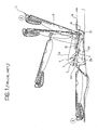
Claim 1. - A seat of the above-mentioned type is known from European patent application EP 0 899 152, from which Figure 1 of the appended drawings is taken.
- With reference to Figure 1, a
seat 1 for the third row of a motor vehicle comprises basically aseat cushion 2 and aseat backrest 3 hinged thereto about anaxis 4, and can be moved from a normal-use position A, in which the seat is capable of receiving a person, to a non-use position B, in which the seat forms a loading area substantially flat and aligned with the vehicle floor. - The
seat 1 is provided with a double-lever driving mechanism 7 comprising a pair ofrotating levers seat cushion 2 to allow the cushion to rotate about 180° forward and, at the same time, shift a predetermined extent backward. The levers 9e 10 have their respective upper ends articulated to a body 5 for support of theseat cushion 2 and their respective lower ends articulated to a bracket-like sheet member (not visible in Figure 1) attached inside alower room 15 of avehicle floor 16. The movement of the seat from position A to position B controlled by the mechanism 7 involves theseat cushion 2 being completely overturned and put in theroom 15 with its cushion surface 2a facing downward and itslower surface 2b facing upward and arranged substantially in alignment with thevehicle floor 16 and theseat backrest 3. - It is an object of the present invention to provide an improved seat compared to the above-discussed prior art, which can be moved easily between the use position and the non-use position and takes up as little room as possible inside the passenger compartment when it is in the non-use position, in order to ensure the greatest load capacity on board of the vehicle.
- This object is fully achieved according to the present invention by a seat as defined in the characterising portion of
Claim 1. - The invention will be illustrated in detail hereinafter purely by way of non-limiting example, with reference to the appended drawings, in which:
- Figure 1 is a view sectioned along a longitudinal vertical plane of a seat according to the prior art, in which its limit positions, that is, the use position and the non-use position, and two intermediate positions between said limit positions are shown;
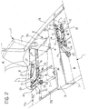
- Figure 2 is a perspective view illustrating schematically a pair of seats according to the present invention, the one in the use position and the other in the non-use position;
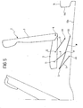
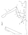
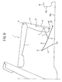
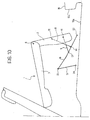
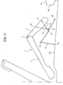
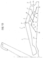
- Figures 3 to 14 are side-elevation schematic views illustrating in succession some of the different positions assumed by a seat according to the present invention when it is moved from the use position to the non-use position.
- In the description and the claims which follow, terms such as "front" or "rear", "upper" or "lower", "longitudinal" or "transverse" are to be intended as referred to the mounted condition on the motor vehicle.
- For clear reasons of simplicity, only one of the two symmetric parts constituting the structure of the seat in question will be described, remaining obviously understood that the non-described part is to be considered as identical, or substantially identical, to the one described.
- In Figure 2, where parts and elements identical or similar to those in Figure 1 (prior art) have been given the same reference numerals, a pair of
seats 1 for a rear row of a motor vehicle are illustrated, each of the seats being of the type comprising aseat cushion 2 and aseat backrest 3 hinged thereto about anaxis 4. Theseats 1 are arranged, respectively, in a first position A, or use position, in which the seat is capable of receiving an occupant, and in a second position B, or non-use position, in which the seat is disposed upside-down inside aroom 15 of thevehicle floor 16 with its upper surface substantially aligned with the loading platform of the vehicle. - As in the above-discussed prior art, in order to move the
seat 1 between the use position A and the non-use position B a double-lever mechanism 7 is provided on each side of theseat cushion 2, which mechanism comprises a front rotatinglever 9 and a rearrotating lever 10 theupper ends seat cushion 2. Thelower end 14 of therear lever 10 is articulated to arespective bracket 17, for example, attached to aside wall 15a of theroom 15, whereas thelower end 13 of thefront lever 9 is articulated at an intermediate point to a connectingrod 18 which forms, together with acrank 19, acrank mechanism 20 associated to the mechanism 7. - The connecting
rod 18 is articulated at afront end 21 to thecrank 19 and is provided at the rear end with aslider 22 slidable in a substantially longitudinal direction along astraight guide 23 attached to theside wall 15a of theroom 15. As can be clearly observed in Figure 2, due to reasons of size and correct operation of the seat driving system, the connectingrod 18 has preferably a non-straight shape, with a first and a secondstraight segment first segment 18a is arranged adjacent and substantially parallel to thefront lever 9 of the mechanism 7 when theseat 1 is in the use position A. In this case, thepoint 13 of articulation of thelever 9 to the connectingrod 18 is positioned on the secondstraight segment 18b of the rod. - The
crank 19 is articulated to abracket 25 arranged in theroom 15, for example, attached to abottom plane 15b of this room, at afront end 24 opposite to the end articulated to the connectingrod 18. Also thecrank 19 has a preferably non-straight shape, with two straight segments inclined at an obtuse angle relative to each other. - The double-lever mechanism 7 and the
crank mechanism 20 are arranged to form a driving device for moving the seat between the use position A (Figure 3) and the non-use position B (Figure 14) through a continuous movement, illustrated in Figure 4 to 13, which requires only one initial control by the user. - The two driving devices, each comprising a double-lever mechanism 7 and a
crank mechanism 20, are arranged specularly at the opposite sides of eachseat 1 and are also interconnected advantageously by means of a transverse rod 26 (Figure 2), the lateral ends of which are fixed at the points ofarticulation 13. The use of thetransverse rod 26 assures the synchronous operation of the two driving devices of each seat, thus facilitating the movement between the two positions A and B and avoiding the risk of jamming. - Now, by referring to Figures 4 to 13, it will be described how the seat is moved from the use position A to the non-use position B according to the invention.
- First of all, the
seat backrest 3 of theseat 1 is rotated frontward about theaxis 4 of articulation to the seat cushion 2 (Figure 4), until it assumes a substantially vertical orientation. Then, by pulling (or pushing) the seat backward, the seat is caused to lift and move back (Figures 5 and 6) mainly by virtue of the clockwise rotation of therotating levers crank mechanism 20 is set in motion, though lightly, by virtue of the backward push that thelever 9 acting as a push-rod exerts on thecrank 19 through thehinge 13. As the rotating levers 9 and 10 move towards a vertical position corresponding to an upper dead point of the mechanism 7, the backward movement of the seat tends to prevail on the lift movement. - When the upper dead point of the mechanism 7 is passed (Figures 7 and 8), the seat starts to rotate anticlockwise and overturn frontward since the
front lever 9 is shorter than therear lever 10 and therefore rotates faster. Thus, while thepoint 11 of articulation of thelever 9 tends to align vertically with thepoint 12 of articulation of thelever 10, theseat cushion 2 reaches a substantially vertical position (Figure 9), whereas theseat backrest 3 is in a substantially horizontal position with the headrest abutting with the seat backrest of the seat of the adjacent front row. - At the same time as the rotation of the
seat cushion 2, which takes place substantially about theend 12 of the lever 10 (which stands essentially still during this phase), the backward movement of theend 11 of thelever 9 drags with itself the connecting rod 18 (Figure 10) through thelever 9, now acting as a pull-rod. - Then, the
seat cushion 2 continues to rotate and move backward (Figures 11, 12 and 13) until it achieves at the end a completely overturned position, in which it abuts with the rearvertical wall 15c of the room 15 (Figure 14) and has itslower surface 2b aligned with thevehicle floor 16. By referring again to Figures 11 to 13, it can be seen also that an opening movement of theseat backrest 3 relative to the seat cushion takes place at the same time as the overturning of theseat cushion 2, due to the relative rotation of the two elements about thehinge axis 4, Therefore, at the end of the movement of the seat, theseat backrest 3 is aligned with theseat cushion 2 and thefloor 16 to form a single loading platform. - The movement of the seat in the opposite direction, that is, from the non-use position B to the normal-use position A, takes place symmetrically.
- Compared to the seats of known construction, a seat according to the invention gives the advantage of enabling an increase in the load capacity inside the motor-vehicle passenger compartment, when the seat is in the non-use position, and of being easily movable between the use position and the non-use position.
- According to the prior art discussed in the introductory part of the present specification, following the movement of the seat from the use position to the non-use position, the seat cushion is only overturned 180 degrees, but remains substantially in the same longitudinal position. Therefore, due to the reduced free space between the two rows of seats it is necessary either to move at first the front seat in the non-use position, for example, by closing its cushion and backrest against each other, or to cause the seat backrest to pass below the seat cushion of the front seat during the movement from the use position to the non-use position. Such a necessity reduces unavoidably the ease and quickness of movement of the seat.
- According to the invention, this drawback is eliminated by virtue of that the
crank mechanism 20, in co-operation with the double-lever mechanism 7, causes a backward movement of the seat which reduces significantly the free space between the two rows of seats required for the overturning of the rear seat. - A further important advantage of the invention is that only one initial control is necessary to move the seat between the use and non-use positions, since the different movements of lifting, overturning and backward shifting of the seat cushion and of overturning of the seat backrest take place automatically in succession, just by virtue of the special arrangement of the driving system.
- Naturally, the principle of the invention remaining unchanged, embodiments and manufacturing details may vary widely from those described and illustrated purely by way of non-limiting example.
Claims (8)
- A seat (1) for a rear row of a motor vehicle, of the type comprising a seat cushion (2) and a seat backrest (3) articulated (4) to each other and arranged to be moved between a use position (A), in which the seat is capable of receiving an occupant, and a non-use position (B), in which the seat forms a loading area substantially flat and aligned with the vehicle floor (16); wherein a pair of driving devices are provided at the sides of the seat cushion (2) in order to move the seat between the above positions (A, B); each device comprising a double-lever mechanism (7) with a front rotating lever (9) and a rear rotating lever (10); each of the levers (9, 10) having an end articulated (11, 12) to the seat cushion (2); the rear lever (10) being also arranged rotatably about a first fixed point (14);
characterised in that each driving device comprises also a crank mechanism (20) with a connecting rod (18) and a crank (19), associated to the double-lever mechanism (7); wherein the crank (19) is arranged rotatably about a second fixed point (24) and is articulated (21) to the connecting rod (18), and the connecting rod (18) is provided, at the opposite end from the that articulated to the crank (19), with a slider (22) slidable in a substantially longitudinal direction along a respective straight guide (23); the connecting rod (18) being also articulated to the rear lever (10) of the associated mechanism (7) in an intermediate point (13) between its ends (21, 22). - A seat according to Claim 1, characterised in that the front lever (9) of the double-lever mechanism (7) is shorter than the rear lever (10), so that the front lever rotates faster than the rear lever as a result of the backward movement of the seat, thus causing a forward rotation of the seat cushion (2).
- A seat according to Claim 1 or 2, characterised in that the connecting rod (18) of the crank mechanism (20) has first and second substantially straight segments (18a, 18b) inclined at an obtuse angle relative to each other, wherein the said first segment is adjacent and substantially parallel to the front lever (9) of the double-lever mechanism (7) when the seat is in the use position (A).
- A seat according to Claim 3, characterised in that also the crank (19) of the crank mechanism (20) has a substantially obtuse-angled shape.
- A seat according to any of the preceding claims, characterised in that the two driving devices are arranged to move the seat (1) between the use and non-use positions (A, B) through a continuous movement as a result of a single initial control imparted by the user.
- A seat according to any of the preceding claims, characterised in that the two driving devices are interconnected by means of a transverse rod (26), the lateral ends of which are fixed at the above points of articulation (13).
- A seat according to Claim 1, characterised in that in the use position (A) the seat is arranged above a room (15) provided in the vehicle floor (16), whereas in the non-use position (B) the seat is entirely accommodated in the room (15) and substantially aligned with the seat cushion (2), with the seat cushion (2) overturned and the seat backrest (3) horizontally arranged.
- A seat according to Claim 7, characterised in that each straight guide (23) for guiding the sliding movement of the slider (22) of the respective connecting rod (18) is attached to a lateral vertical wall (15a) of the room (15).
Applications Claiming Priority (2)
| Application Number | Priority Date | Filing Date | Title |
|---|---|---|---|
| IT2001TO000990A ITTO20010990A1 (en) | 2001-10-18 | 2001-10-18 | TIPPING SEAT FOR A REAR ROW OF A VEHICLE. |
| ITTO20010990 | 2001-10-18 |
Publications (3)
| Publication Number | Publication Date |
|---|---|
| EP1304256A2 true EP1304256A2 (en) | 2003-04-23 |
| EP1304256A3 EP1304256A3 (en) | 2003-09-10 |
| EP1304256B1 EP1304256B1 (en) | 2005-01-19 |
Family
ID=11459267
Family Applications (1)
| Application Number | Title | Priority Date | Filing Date |
|---|---|---|---|
| EP02022862A Expired - Lifetime EP1304256B1 (en) | 2001-10-18 | 2002-10-14 | A tiltable rear seat for a motor vehicle |
Country Status (5)
| Country | Link |
|---|---|
| EP (1) | EP1304256B1 (en) |
| AT (1) | ATE287348T1 (en) |
| DE (1) | DE60202652T2 (en) |
| ES (1) | ES2236419T3 (en) |
| IT (1) | ITTO20010990A1 (en) |
Cited By (4)
| Publication number | Priority date | Publication date | Assignee | Title |
|---|---|---|---|---|
| FR2849629A1 (en) * | 2003-01-06 | 2004-07-09 | Faurecia Automotive Seating Ca | Folding seat assembly for vehicle, has mounting part engaged/disengaged with floor pan in respective deployed and folded configurations, where seat pad component has horizontal and vertical orientation in respective configurations |
| WO2005037600A1 (en) * | 2003-10-13 | 2005-04-28 | Johnson Controls Gmbh | Seat comprising a pivotable seat cushion part |
| FR2863560A1 (en) * | 2003-12-10 | 2005-06-17 | Volkswagen Ag | SEAT OF MOTOR VEHICLE WITH SEPARATE SHREDDING OF SEAT BLOCK AND FOLDER ELEMENT |
| DE10236490B4 (en) * | 2002-08-09 | 2005-06-23 | Faurecia Autositze Gmbh & Co. Kg | Automotive seat |
Citations (1)
| Publication number | Priority date | Publication date | Assignee | Title |
|---|---|---|---|---|
| EP0899152A2 (en) | 1997-08-27 | 1999-03-03 | Adam Opel Ag | Seat, particularly for a third row of an automotive vehicle |
Family Cites Families (6)
| Publication number | Priority date | Publication date | Assignee | Title |
|---|---|---|---|---|
| FR1577124A (en) * | 1968-08-26 | 1969-08-01 | ||
| FR2411105A1 (en) * | 1977-12-09 | 1979-07-06 | Peugeot | ADVANCED TRANSFORMABLE SEAT FOR MOTOR VEHICLES |
| DE4422920A1 (en) * | 1994-06-30 | 1996-01-04 | Opel Adam Ag | Seat arrangement, in particular for the loading or passenger compartment of a motor vehicle |
| DE19842824B4 (en) * | 1998-09-18 | 2010-09-30 | Volkswagen Ag | Seat arrangement in a vehicle |
| DE19931013A1 (en) * | 1999-07-06 | 2001-01-11 | Volkswagen Ag | Foldable seat arrangement in a motor vehicle |
| DE19943891C1 (en) * | 1999-09-14 | 2000-11-16 | Faure Bertrand Sitztech Gmbh | Automobile rear seating has seat struts on both sides attached to leading and trailing linkage points to give a flat surface when the rear backrest is folded down to increase the luggage compartment space |
-
2001
- 2001-10-18 IT IT2001TO000990A patent/ITTO20010990A1/en unknown
-
2002
- 2002-10-14 EP EP02022862A patent/EP1304256B1/en not_active Expired - Lifetime
- 2002-10-14 AT AT02022862T patent/ATE287348T1/en not_active IP Right Cessation
- 2002-10-14 ES ES02022862T patent/ES2236419T3/en not_active Expired - Lifetime
- 2002-10-14 DE DE60202652T patent/DE60202652T2/en not_active Expired - Lifetime
Patent Citations (1)
| Publication number | Priority date | Publication date | Assignee | Title |
|---|---|---|---|---|
| EP0899152A2 (en) | 1997-08-27 | 1999-03-03 | Adam Opel Ag | Seat, particularly for a third row of an automotive vehicle |
Cited By (6)
| Publication number | Priority date | Publication date | Assignee | Title |
|---|---|---|---|---|
| DE10236490B4 (en) * | 2002-08-09 | 2005-06-23 | Faurecia Autositze Gmbh & Co. Kg | Automotive seat |
| FR2849629A1 (en) * | 2003-01-06 | 2004-07-09 | Faurecia Automotive Seating Ca | Folding seat assembly for vehicle, has mounting part engaged/disengaged with floor pan in respective deployed and folded configurations, where seat pad component has horizontal and vertical orientation in respective configurations |
| WO2005037600A1 (en) * | 2003-10-13 | 2005-04-28 | Johnson Controls Gmbh | Seat comprising a pivotable seat cushion part |
| DE10348085B4 (en) * | 2003-10-13 | 2005-10-13 | Johnson Controls Gmbh | Seat with swivel seat cushion part |
| US7210741B2 (en) | 2003-10-13 | 2007-05-01 | Johnson Controls Gmbh | Seat having pivotable seat cushion |
| FR2863560A1 (en) * | 2003-12-10 | 2005-06-17 | Volkswagen Ag | SEAT OF MOTOR VEHICLE WITH SEPARATE SHREDDING OF SEAT BLOCK AND FOLDER ELEMENT |
Also Published As
| Publication number | Publication date |
|---|---|
| ATE287348T1 (en) | 2005-02-15 |
| ES2236419T3 (en) | 2005-07-16 |
| DE60202652D1 (en) | 2005-02-24 |
| ITTO20010990A1 (en) | 2003-04-18 |
| DE60202652T2 (en) | 2006-01-05 |
| EP1304256B1 (en) | 2005-01-19 |
| EP1304256A3 (en) | 2003-09-10 |
Similar Documents
| Publication | Publication Date | Title |
|---|---|---|
| EP1892143B1 (en) | Vehicle seat assembly | |
| CN111601732B (en) | Vehicle seat convenient to enter | |
| CN110979112B (en) | Vehicle seat | |
| KR101058762B1 (en) | Car seat device | |
| CN112124158B (en) | Vehicle seat with tiltable backrest | |
| US7066539B2 (en) | Vehicle seat of retractable type | |
| US6464299B1 (en) | Vehicle seat | |
| US7607735B2 (en) | Vehicle seats | |
| WO2006030539A1 (en) | Walk-in device | |
| CN105452054A (en) | Easy-entry adjustment mechanism for dive-down vehicle seats or seat systems | |
| EP2075153A1 (en) | Motor vehicle seat assembly equipped with a load floor for a rear boot | |
| KR20230064716A (en) | Device for adjusting seat of vehicle | |
| JP2008049845A (en) | Automotive seat device | |
| JPH0725242A (en) | Vehicle sunroof device | |
| US20170113575A1 (en) | Seat for motor vehicle and motor vehicle comprising such a seat | |
| EP1304256B1 (en) | A tiltable rear seat for a motor vehicle | |
| EP2046600B1 (en) | Seat assembly provided with an articulated-quadrilateral supporting device for a motor vehicle | |
| JP5363156B2 (en) | Vehicle seat | |
| US7413232B1 (en) | Vehicle seat lifting unit | |
| CN101018690A (en) | Stowable seat | |
| KR20050063665A (en) | Seat for vehicle | |
| JP2003040010A (en) | Vehicle seat with tip-up mechanism | |
| JP4019705B2 (en) | Sheet device | |
| JP7845215B2 (en) | Vehicle seating system | |
| KR100501671B1 (en) | Apparatus for Adjusting Seat-Back Angle |
Legal Events
| Date | Code | Title | Description |
|---|---|---|---|
| PUAI | Public reference made under article 153(3) epc to a published international application that has entered the european phase |
Free format text: ORIGINAL CODE: 0009012 |
|
| AK | Designated contracting states |
Designated state(s): AT BE BG CH CY CZ DE DK EE ES FI FR GB GR IE IT LI LU MC NL PT SE SK TR |
|
| AX | Request for extension of the european patent |
Extension state: AL LT LV MK RO SI |
|
| PUAL | Search report despatched |
Free format text: ORIGINAL CODE: 0009013 |
|
| AK | Designated contracting states |
Kind code of ref document: A3 Designated state(s): AT BE BG CH CY CZ DE DK EE ES FI FR GB GR IE IT LI LU MC NL PT SE SK TR |
|
| AX | Request for extension of the european patent |
Extension state: AL LT LV MK RO SI |
|
| GRAP | Despatch of communication of intention to grant a patent |
Free format text: ORIGINAL CODE: EPIDOSNIGR1 |
|
| 17P | Request for examination filed |
Effective date: 20040304 |
|
| AKX | Designation fees paid |
Designated state(s): AT BE BG CH CY CZ DE DK EE ES FI FR GB GR IE IT LI LU MC NL PT SE SK TR |
|
| GRAS | Grant fee paid |
Free format text: ORIGINAL CODE: EPIDOSNIGR3 |
|
| RAP1 | Party data changed (applicant data changed or rights of an application transferred) |
Owner name: WIDE DESIGN S.P.A. |
|
| RAP1 | Party data changed (applicant data changed or rights of an application transferred) |
Owner name: ITALDESIGN-GIUGIARO S.P.A |
|
| GRAA | (expected) grant |
Free format text: ORIGINAL CODE: 0009210 |
|
| AK | Designated contracting states |
Kind code of ref document: B1 Designated state(s): AT BE BG CH CY CZ DE DK EE ES FI FR GB GR IE IT LI LU MC NL PT SE SK TR |
|
| PG25 | Lapsed in a contracting state [announced via postgrant information from national office to epo] |
Ref country code: LI Free format text: LAPSE BECAUSE OF FAILURE TO SUBMIT A TRANSLATION OF THE DESCRIPTION OR TO PAY THE FEE WITHIN THE PRESCRIBED TIME-LIMIT Effective date: 20050119 Ref country code: BE Free format text: LAPSE BECAUSE OF FAILURE TO SUBMIT A TRANSLATION OF THE DESCRIPTION OR TO PAY THE FEE WITHIN THE PRESCRIBED TIME-LIMIT Effective date: 20050119 Ref country code: FI Free format text: LAPSE BECAUSE OF FAILURE TO SUBMIT A TRANSLATION OF THE DESCRIPTION OR TO PAY THE FEE WITHIN THE PRESCRIBED TIME-LIMIT Effective date: 20050119 Ref country code: AT Free format text: LAPSE BECAUSE OF FAILURE TO SUBMIT A TRANSLATION OF THE DESCRIPTION OR TO PAY THE FEE WITHIN THE PRESCRIBED TIME-LIMIT Effective date: 20050119 Ref country code: BG Free format text: LAPSE BECAUSE OF FAILURE TO SUBMIT A TRANSLATION OF THE DESCRIPTION OR TO PAY THE FEE WITHIN THE PRESCRIBED TIME-LIMIT Effective date: 20050119 Ref country code: TR Free format text: LAPSE BECAUSE OF FAILURE TO SUBMIT A TRANSLATION OF THE DESCRIPTION OR TO PAY THE FEE WITHIN THE PRESCRIBED TIME-LIMIT Effective date: 20050119 Ref country code: NL Free format text: LAPSE BECAUSE OF FAILURE TO SUBMIT A TRANSLATION OF THE DESCRIPTION OR TO PAY THE FEE WITHIN THE PRESCRIBED TIME-LIMIT Effective date: 20050119 Ref country code: EE Free format text: LAPSE BECAUSE OF FAILURE TO SUBMIT A TRANSLATION OF THE DESCRIPTION OR TO PAY THE FEE WITHIN THE PRESCRIBED TIME-LIMIT Effective date: 20050119 Ref country code: CH Free format text: LAPSE BECAUSE OF FAILURE TO SUBMIT A TRANSLATION OF THE DESCRIPTION OR TO PAY THE FEE WITHIN THE PRESCRIBED TIME-LIMIT Effective date: 20050119 Ref country code: CZ Free format text: LAPSE BECAUSE OF FAILURE TO SUBMIT A TRANSLATION OF THE DESCRIPTION OR TO PAY THE FEE WITHIN THE PRESCRIBED TIME-LIMIT Effective date: 20050119 Ref country code: SK Free format text: LAPSE BECAUSE OF FAILURE TO SUBMIT A TRANSLATION OF THE DESCRIPTION OR TO PAY THE FEE WITHIN THE PRESCRIBED TIME-LIMIT Effective date: 20050119 Ref country code: IT Free format text: LAPSE BECAUSE OF FAILURE TO SUBMIT A TRANSLATION OF THE DESCRIPTION OR TO PAY THE FEE WITHIN THE PRESCRIBED TIME-LIMIT;WARNING: LAPSES OF ITALIAN PATENTS WITH EFFECTIVE DATE BEFORE 2007 MAY HAVE OCCURRED AT ANY TIME BEFORE 2007. THE CORRECT EFFECTIVE DATE MAY BE DIFFERENT FROM THE ONE RECORDED. Effective date: 20050119 |
|
| REG | Reference to a national code |
Ref country code: GB Ref legal event code: FG4D |
|
| REG | Reference to a national code |
Ref country code: CH Ref legal event code: EP |
|
| REG | Reference to a national code |
Ref country code: IE Ref legal event code: FG4D |
|
| REF | Corresponds to: |
Ref document number: 60202652 Country of ref document: DE Date of ref document: 20050224 Kind code of ref document: P |
|
| PG25 | Lapsed in a contracting state [announced via postgrant information from national office to epo] |
Ref country code: GR Free format text: LAPSE BECAUSE OF FAILURE TO SUBMIT A TRANSLATION OF THE DESCRIPTION OR TO PAY THE FEE WITHIN THE PRESCRIBED TIME-LIMIT Effective date: 20050419 Ref country code: DK Free format text: LAPSE BECAUSE OF FAILURE TO SUBMIT A TRANSLATION OF THE DESCRIPTION OR TO PAY THE FEE WITHIN THE PRESCRIBED TIME-LIMIT Effective date: 20050419 |
|
| REG | Reference to a national code |
Ref country code: SE Ref legal event code: TRGR |
|
| NLV1 | Nl: lapsed or annulled due to failure to fulfill the requirements of art. 29p and 29m of the patents act | ||
| REG | Reference to a national code |
Ref country code: ES Ref legal event code: FG2A Ref document number: 2236419 Country of ref document: ES Kind code of ref document: T3 |
|
| REG | Reference to a national code |
Ref country code: CH Ref legal event code: PL |
|
| PG25 | Lapsed in a contracting state [announced via postgrant information from national office to epo] |
Ref country code: IE Free format text: LAPSE BECAUSE OF NON-PAYMENT OF DUE FEES Effective date: 20051014 Ref country code: CY Free format text: LAPSE BECAUSE OF FAILURE TO SUBMIT A TRANSLATION OF THE DESCRIPTION OR TO PAY THE FEE WITHIN THE PRESCRIBED TIME-LIMIT Effective date: 20051014 |
|
| PG25 | Lapsed in a contracting state [announced via postgrant information from national office to epo] |
Ref country code: MC Free format text: LAPSE BECAUSE OF NON-PAYMENT OF DUE FEES Effective date: 20051031 Ref country code: LU Free format text: LAPSE BECAUSE OF NON-PAYMENT OF DUE FEES Effective date: 20051031 |
|
| PLBE | No opposition filed within time limit |
Free format text: ORIGINAL CODE: 0009261 |
|
| STAA | Information on the status of an ep patent application or granted ep patent |
Free format text: STATUS: NO OPPOSITION FILED WITHIN TIME LIMIT |
|
| ET | Fr: translation filed | ||
| 26N | No opposition filed |
Effective date: 20051020 |
|
| REG | Reference to a national code |
Ref country code: IE Ref legal event code: MM4A |
|
| PG25 | Lapsed in a contracting state [announced via postgrant information from national office to epo] |
Ref country code: PT Free format text: LAPSE BECAUSE OF NON-PAYMENT OF DUE FEES Effective date: 20050619 |
|
| REG | Reference to a national code |
Ref country code: FR Ref legal event code: PLFP Year of fee payment: 14 |
|
| REG | Reference to a national code |
Ref country code: FR Ref legal event code: PLFP Year of fee payment: 15 |
|
| REG | Reference to a national code |
Ref country code: FR Ref legal event code: PLFP Year of fee payment: 16 |
|
| REG | Reference to a national code |
Ref country code: FR Ref legal event code: PLFP Year of fee payment: 17 |
|
| PGFP | Annual fee paid to national office [announced via postgrant information from national office to epo] |
Ref country code: SE Payment date: 20191016 Year of fee payment: 18 Ref country code: DE Payment date: 20191031 Year of fee payment: 18 |
|
| PGFP | Annual fee paid to national office [announced via postgrant information from national office to epo] |
Ref country code: ES Payment date: 20191105 Year of fee payment: 18 |
|
| PGFP | Annual fee paid to national office [announced via postgrant information from national office to epo] |
Ref country code: GB Payment date: 20191021 Year of fee payment: 18 |
|
| PGFP | Annual fee paid to national office [announced via postgrant information from national office to epo] |
Ref country code: FR Payment date: 20200114 Year of fee payment: 18 |
|
| REG | Reference to a national code |
Ref country code: DE Ref legal event code: R119 Ref document number: 60202652 Country of ref document: DE |
|
| REG | Reference to a national code |
Ref country code: SE Ref legal event code: EUG |
|
| GBPC | Gb: european patent ceased through non-payment of renewal fee |
Effective date: 20201014 |
|
| PG25 | Lapsed in a contracting state [announced via postgrant information from national office to epo] |
Ref country code: DE Free format text: LAPSE BECAUSE OF NON-PAYMENT OF DUE FEES Effective date: 20210501 Ref country code: FR Free format text: LAPSE BECAUSE OF NON-PAYMENT OF DUE FEES Effective date: 20201031 |
|
| PG25 | Lapsed in a contracting state [announced via postgrant information from national office to epo] |
Ref country code: SE Free format text: LAPSE BECAUSE OF NON-PAYMENT OF DUE FEES Effective date: 20201015 Ref country code: GB Free format text: LAPSE BECAUSE OF NON-PAYMENT OF DUE FEES Effective date: 20201014 |
|
| REG | Reference to a national code |
Ref country code: ES Ref legal event code: FD2A Effective date: 20220121 |
|
| PG25 | Lapsed in a contracting state [announced via postgrant information from national office to epo] |
Ref country code: ES Free format text: LAPSE BECAUSE OF NON-PAYMENT OF DUE FEES Effective date: 20201015 |