EP1304281B1 - Véhicule ayant un longeron lateral muni d'un insert de renforcement - Google Patents
Véhicule ayant un longeron lateral muni d'un insert de renforcement Download PDFInfo
- Publication number
- EP1304281B1 EP1304281B1 EP02017883A EP02017883A EP1304281B1 EP 1304281 B1 EP1304281 B1 EP 1304281B1 EP 02017883 A EP02017883 A EP 02017883A EP 02017883 A EP02017883 A EP 02017883A EP 1304281 B1 EP1304281 B1 EP 1304281B1
- Authority
- EP
- European Patent Office
- Prior art keywords
- fastening
- vehicle
- reinforcing tube
- fastening bracket
- compensating members
- Prior art date
- Legal status (The legal status is an assumption and is not a legal conclusion. Google has not performed a legal analysis and makes no representation as to the accuracy of the status listed.)
- Expired - Lifetime
Links
Images


Classifications
-
- B—PERFORMING OPERATIONS; TRANSPORTING
- B62—LAND VEHICLES FOR TRAVELLING OTHERWISE THAN ON RAILS
- B62D—MOTOR VEHICLES; TRAILERS
- B62D21/00—Understructures, i.e. chassis frame on which a vehicle body may be mounted
- B62D21/15—Understructures, i.e. chassis frame on which a vehicle body may be mounted having impact absorbing means, e.g. a frame designed to permanently or temporarily change shape or dimension upon impact with another body
- B62D21/157—Understructures, i.e. chassis frame on which a vehicle body may be mounted having impact absorbing means, e.g. a frame designed to permanently or temporarily change shape or dimension upon impact with another body for side impacts
-
- B—PERFORMING OPERATIONS; TRANSPORTING
- B62—LAND VEHICLES FOR TRAVELLING OTHERWISE THAN ON RAILS
- B62D—MOTOR VEHICLES; TRAILERS
- B62D25/00—Superstructure or monocoque structure sub-units; Parts or details thereof not otherwise provided for
- B62D25/02—Side panels
- B62D25/025—Side sills thereof
Definitions
- the invention relates to a vehicle having a reinforcement arranged in the longitudinal sill of a vehicle body according to the preamble of patent claim 1.
- a reinforcing tube in a longitudinal sill of a vehicle is known, which is connected via the vehicle pillars with the vehicle body.
- Such a reinforcing tube is fastened in a first step to the outer vehicle pillars A and C and then in a second step, attachment to the middle B-pillar. Due to tolerances and also by thermal stresses, the reinforcing tube may under certain circumstances have a deviating from its longitudinal axis shape, that is, the reinforcing tube is provided with a so-called buckling in any direction.
- the object of the invention is to provide an attachment of the reinforcing tube to the middle B-pillar in such a way, whereby the reinforcing tube can be fastened without deformation of the vehicle body structure even if deviating from its longitudinal axis.
- the middle mounting bracket with the interposition of compensating elements on the reinforcing tube can be fastened, for which the compensating elements projecting fastening tabs, which are connectable to the mounting brine.
- the compensating elements consist of the half-shells that are aligned with the fastening bracket, which are fastened welded to the reinforcing tube and the fastening tabs are offset at right angles from the plane of the half-shells.
- the fastening tabs are each made of semicircular circumferential on the outer edge and the other fastening tabs are provided on the inner edge only in sections.
- the mounting bracket is arranged in the assembled state between the semicircular circumferential mounting tabs of the compensation elements and the other sections provided inwardly provided mounting tabs project through slots of the mounting bracket.
- the mounting bracket is arranged to the compensating elements in response to the fixed position of the reinforcing tube to the pillars A and C of the vehicle such that a deviating from a longitudinal axis reinforcing tube to the B-pillar of the vehicle via the spaced apart from the compensating elements mounting bracket can be fastened.
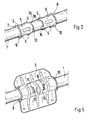
- a reinforcing tube 1 is arranged in the longitudinal rocker Ls of a vehicle for crash absorption and is fastened to an A, B and C pillar in the vehicle body for this purpose.
- FIG. 1 these columns A, B and C are indicated schematically.
- brackets 2, 3 and 4 are provided, which are connectable either directly or with the interposition of one or more adjacent balancing elements 5, 6 with the vehicle pillar B.
- the mounting brackets 2 and 4 are connected at the free ends of the reinforcing tube 1 directly by welding to the column A and C.
- the middle mounting bracket 3 is indirectly secured with the interposition of balancing elements 5 and 6 on the B-pillar.
- the compensation elements 5, 6 consist of half-shells which are trimmed to the attachment bracket 3.
- the compensation element 5, 6 are each firmly connected to the reinforcing tube 1 via a plurality of welds S.
- the mounting bracket 3 is placed, positioned and secured by welds S1 and S2.
- the compensating elements 5, 6 on the outer edge 7, 8 respectively projecting or parked fastening tabs 9, 10 and the inner edge 11, 12 each further parked fastening tabs 13, 14, which may be provided only in sections.
- the mounting bracket 3 is disposed between the outer fastening tabs 9 and 10, whereas the inner fastening tabs 13, 14 protrude through slots 15, 16 in the mounting bracket 3.
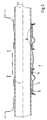
- connection of the reinforcing tube 1 with the vehicle pillars A, B and C takes place in such a way that first takes place a fastening of the reinforcing tube 1 via the connected to the pipe 1 mounting brackets 2 and 4 with the columns A and C. Since the reinforcing tube 1 can deform due to thermal stresses or the reinforcing tube 1 already in the delivered state has a deformation in the longitudinal direction or to the longitudinal axis Lo, the compensating elements 5 and 6 are placed and connected to the tube 1 to compensate for these deviations. If, for example, the tube 1 has a buckling in the Z direction (FIG. 4), no connection with the B pillar can normally take place without compensating elements 5, 6; unless it is improperly deformed.
- the mounting bracket 3 can be placed on the compensating elements 5, 6 and by means of the fastening tabs 9, 10 and 13, 14 with the tube 1 under recording the tolerances are connected.
- the connection of the mounting bracket 3 with the B-pillar is done directly on the legs 19 and 20 of the mounting bracket.
Landscapes
- Engineering & Computer Science (AREA)
- Chemical & Material Sciences (AREA)
- Combustion & Propulsion (AREA)
- Transportation (AREA)
- Mechanical Engineering (AREA)
- Body Structure For Vehicles (AREA)
Claims (5)
- Véhicule avec un renforcement disposé dans le longeron d'une carrosserie de véhicule, lequel renforcement est constitué d'un élément tubulaire qui peut être relié aux montants du véhicule par l'intermédiaire de consoles de fixation d'extrémités et d'une console de fixation centrale, caractérisé en ce que la console de fixation centrale (3) peut être fixée au tube de renforcement (1) en intercalant des éléments compensateurs (5, 6), les éléments compensateurs (5, 6) comportant pour cela des languettes de fixation faisant saillie (9, 10 et 13, 14) qui peuvent être reliées à la console de fixation (3).
- Véhicule selon la revendication 1, caractérisé en ce que les éléments compensateurs (5, 6) sont constitués par les demi-coquilles dirigées vers la console de fixation (3) qui peuvent être fixées par soudure au tube de renforcement (1) et les languettes de fixation (9, 10 et 13, 14) sont décalées à angle droit par rapport au plan des demi-coquilles.
- Véhicule selon les revendications 1 ou 2, caractérisé en ce que les languettes de fixation (9, 10) ont une configuration semi-circulaire sur le bord extérieur (7, 8) et les autres languettes de fixation (13, 14) s'étendent seulement par tronçons sur le bord intérieur (7a, 8a).
- Véhicule selon les revendications 1, 2 ou 3, caractérisé en ce que, à l'état assemblé, la console de fixation (3) est disposée entre les languettes de fixation semi-circulaires (9, 10) des éléments compensateurs (5, 6) et les autres languettes de fixation intérieures prévues par tronçons (13, 14) font saillie dans des fentes (15, 16) de la console de fixation (3).
- Véhicule selon une ou plusieurs des revendications précédentes, caractérisé en ce que la console de fixation (3) est disposée sur les montants (A et B) du véhicule par rapport aux éléments compensateurs (5, 6) en fonction de la position de fixation du tube de renforcement (1) de telle manière qu'un tube de renforcement (1) s'écartant d'un axe longitudinal (L0) peut être fixé au montant B de la carrosserie du véhicule par l'intermédiaire de la console de fixation (3) espacée des éléments compensateurs (5, 6) sur la distance (a).
Applications Claiming Priority (2)
| Application Number | Priority Date | Filing Date | Title |
|---|---|---|---|
| DE10151768 | 2001-10-19 | ||
| DE10151768A DE10151768B4 (de) | 2001-10-19 | 2001-10-19 | Fahrzeug |
Publications (3)
| Publication Number | Publication Date |
|---|---|
| EP1304281A2 EP1304281A2 (fr) | 2003-04-23 |
| EP1304281A3 EP1304281A3 (fr) | 2004-11-10 |
| EP1304281B1 true EP1304281B1 (fr) | 2006-06-21 |
Family
ID=7703119
Family Applications (1)
| Application Number | Title | Priority Date | Filing Date |
|---|---|---|---|
| EP02017883A Expired - Lifetime EP1304281B1 (fr) | 2001-10-19 | 2002-08-09 | Véhicule ayant un longeron lateral muni d'un insert de renforcement |
Country Status (6)
| Country | Link |
|---|---|
| US (1) | US6666500B2 (fr) |
| EP (1) | EP1304281B1 (fr) |
| JP (1) | JP3769528B2 (fr) |
| AT (1) | ATE330834T1 (fr) |
| DE (2) | DE10151768B4 (fr) |
| ES (1) | ES2261566T3 (fr) |
Cited By (1)
| Publication number | Priority date | Publication date | Assignee | Title |
|---|---|---|---|---|
| US8857852B2 (en) | 2011-06-07 | 2014-10-14 | F-Tech Inc. | Beam member |
Families Citing this family (21)
| Publication number | Priority date | Publication date | Assignee | Title |
|---|---|---|---|---|
| US7413242B2 (en) | 2003-09-03 | 2008-08-19 | Specialty Vehicle Acquisition Corp. | Structural seat system for an automotive vehicle |
| US7481486B2 (en) | 2003-09-03 | 2009-01-27 | Specialty Vehicle Acquisition Corp. | Structural seat system for an automotive vehicle |
| US7246845B2 (en) * | 2003-09-03 | 2007-07-24 | Asc Incorporated | Structural seat system for an automotive vehicle |
| US7413240B2 (en) * | 2003-09-03 | 2008-08-19 | Specialty Vehicle Acquisition Corp. | Structural system for a convertible automotive vehicle |
| US6926351B2 (en) * | 2003-09-17 | 2005-08-09 | Daimlerchrysler Corporation | Convertible vehicle uni-body having and internal supplemental support structure |
| JP4543996B2 (ja) * | 2005-03-29 | 2010-09-15 | コベルコ建機株式会社 | 作業機械 |
| USD543135S1 (en) | 2005-08-12 | 2007-05-22 | Asc Incorporated | Automotive vehicle and/or toy replica thereof |
| FR2892089B1 (fr) * | 2005-10-13 | 2007-12-07 | Peugeot Citroen Automobiles Sa | Structure de vehicule automobile comprenant un element d'entretoise |
| FR2892090B1 (fr) * | 2005-10-13 | 2009-05-08 | Peugeot Citroen Automobiles Sa | Procede de realisation d'une structure de vehicule automobile |
| FR2915451B1 (fr) * | 2007-04-26 | 2009-10-09 | Vallourec Vitry | Prolonge avec appui perfectionne. |
| JP4368915B2 (ja) * | 2007-07-24 | 2009-11-18 | 本田技研工業株式会社 | 車両用ドアの構造 |
| DE102009027334A1 (de) * | 2009-06-30 | 2011-01-05 | Deere & Company, Moline | Rahmenkonstruktion |
| US9376142B2 (en) * | 2014-05-22 | 2016-06-28 | Nissan North America, Inc. | Vehicle support structure |
| CN104590383A (zh) * | 2015-01-30 | 2015-05-06 | 安徽机电职业技术学院 | 一种车身侧围加强及保护结构 |
| CN108016502A (zh) * | 2016-10-28 | 2018-05-11 | 长城汽车股份有限公司 | 汽车门槛加强梁结构 |
| CN107985420B (zh) * | 2017-11-20 | 2020-07-10 | 东风汽车公司 | 汽车桁架式防潜梁结构及其连接结构 |
| US10293862B1 (en) * | 2018-01-12 | 2019-05-21 | Ford Global Technologies, Llc | Side sill assembly reinforced with a tube and box-shaped brackets |
| CN112238905A (zh) * | 2020-06-24 | 2021-01-19 | 北京新能源汽车技术创新中心有限公司 | 地板纵梁加强件、地板纵梁结构以及车辆 |
| JP7197659B1 (ja) * | 2021-10-15 | 2022-12-27 | 株式会社神戸製鋼所 | フレーム構造体の製造方法 |
| US11845493B1 (en) | 2022-05-26 | 2023-12-19 | Ford Global Technologies, Llc | Body structure for vehicle having reinforcement assembly |
| CN115583289A (zh) * | 2022-09-23 | 2023-01-10 | 重庆长安汽车股份有限公司 | 一种可提升碰撞性能的b柱总成结构及汽车 |
Family Cites Families (9)
| Publication number | Priority date | Publication date | Assignee | Title |
|---|---|---|---|---|
| DE3011345C2 (de) * | 1980-03-25 | 1982-04-29 | Daimler-Benz Ag, 7000 Stuttgart | Verbindung von Rohren mit Randbereichen von Blechen o.dgl. flächigen Bauteilen |
| DE4016730A1 (de) * | 1990-05-24 | 1991-11-28 | Daimler Benz Ag | Tragsaeule fuer den karosserierahmen eines kraftfahrzeuges |
| JPH0699581A (ja) * | 1992-09-21 | 1994-04-12 | Seiko Epson Corp | ノズルプレートの製造方法 |
| US5544930A (en) * | 1994-10-05 | 1996-08-13 | Chrysler Corporation | Floating end structural reinforcement for a vehicle door |
| DE19603098C2 (de) * | 1996-01-29 | 1998-03-19 | Daimler Benz Ag | Fahrgastzelle für einen Personenkraftwagen |
| DE19708215C2 (de) * | 1997-02-28 | 2001-06-28 | Audi Ag | Schweller eines Kraftfahrzeugs mit einer Verstärkungseinlage |
| DE19954292C2 (de) * | 1999-11-11 | 2003-04-24 | Porsche Ag | Fahrzeug |
| US6193306B1 (en) * | 1999-12-22 | 2001-02-27 | Ford Global Technologies, Inc. | Support assembly for a vehicle |
| JP3783546B2 (ja) * | 2000-10-11 | 2006-06-07 | 三菱自動車工業株式会社 | 車両のサイドシル構造 |
-
2001
- 2001-10-19 DE DE10151768A patent/DE10151768B4/de not_active Expired - Fee Related
-
2002
- 2002-08-09 DE DE50207271T patent/DE50207271D1/de not_active Expired - Lifetime
- 2002-08-09 AT AT02017883T patent/ATE330834T1/de active
- 2002-08-09 ES ES02017883T patent/ES2261566T3/es not_active Expired - Lifetime
- 2002-08-09 EP EP02017883A patent/EP1304281B1/fr not_active Expired - Lifetime
- 2002-10-16 JP JP2002302170A patent/JP3769528B2/ja not_active Expired - Fee Related
- 2002-10-18 US US10/273,361 patent/US6666500B2/en not_active Expired - Fee Related
Cited By (1)
| Publication number | Priority date | Publication date | Assignee | Title |
|---|---|---|---|---|
| US8857852B2 (en) | 2011-06-07 | 2014-10-14 | F-Tech Inc. | Beam member |
Also Published As
| Publication number | Publication date |
|---|---|
| US6666500B2 (en) | 2003-12-23 |
| ATE330834T1 (de) | 2006-07-15 |
| ES2261566T3 (es) | 2006-11-16 |
| DE50207271D1 (de) | 2006-08-03 |
| EP1304281A2 (fr) | 2003-04-23 |
| US20030085590A1 (en) | 2003-05-08 |
| DE10151768A1 (de) | 2003-04-30 |
| JP2003137130A (ja) | 2003-05-14 |
| JP3769528B2 (ja) | 2006-04-26 |
| EP1304281A3 (fr) | 2004-11-10 |
| DE10151768B4 (de) | 2005-08-18 |
Similar Documents
| Publication | Publication Date | Title |
|---|---|---|
| EP1304281B1 (fr) | Véhicule ayant un longeron lateral muni d'un insert de renforcement | |
| DE69708009T2 (de) | Fahrzeugkarosserie | |
| EP1925536B1 (fr) | Traverses, en particulier traverses de cockpit | |
| DE19954296C2 (de) | Fahrzeug | |
| DE19515979C2 (de) | Hintere Aufbaustruktur eines Fahrzeugs | |
| EP1690779B1 (fr) | Châssis auxiliaire pour véhicules automobiles | |
| DE19730404B4 (de) | Hilfsrahmen für Kraftfahrzeuge | |
| EP2062805B1 (fr) | Structure de carrosserie | |
| EP2457807B1 (fr) | Berceau de véhicule automobile | |
| EP2093131A2 (fr) | Berceau auxiliaire pour l'essieu arrière d'un véhicule automobile | |
| DE102008010553A1 (de) | Hilfsrahmen für eine Vorderachse eines Kraftfahrzeugs | |
| DE19920051A1 (de) | Fahrschemel für eine Vorderachse eines Kraftfahrzeugs | |
| DE19708215A1 (de) | Schweller eines Kraftfahrzeugs mit einer Verstärkungseinlage | |
| DE202014104614U1 (de) | Karosserie und Fahrzeug mit einer solchen Karosserie | |
| DE102016209186B3 (de) | Karosseriestruktur für ein Kraftfahrzeug | |
| EP0603574A1 (fr) | Véhicule à moteur avec éléments de renfort de la carosserie | |
| DE102004012500B4 (de) | Aufbaustruktur für eine Karosserie von Kraftfahrzeugen | |
| DE19709315C2 (de) | Sitzkonsole für einen Kraftfahrzeugsitz | |
| EP1902873B1 (fr) | Faux-châssis avec suspension de roue indépendante et direction à crémaillère pour essieu avant | |
| DE102006033606B4 (de) | Anordnung zur Befestigung einer Lenksäule eines Kraftfahrzeuges | |
| DE102016206649A1 (de) | Hilfsrahmen für ein Fahrzeug | |
| EP3870463B1 (fr) | Bras de suspension à structure de tôle | |
| DE102009021964A1 (de) | Hohlprofil für eine Fahrzeugkarosserie | |
| DE10152184A1 (de) | Tragstruktur für ein Nutzfahrzeug | |
| DE10221654A1 (de) | Querträger für ein Kraftfahrzeug |
Legal Events
| Date | Code | Title | Description |
|---|---|---|---|
| PUAI | Public reference made under article 153(3) epc to a published international application that has entered the european phase |
Free format text: ORIGINAL CODE: 0009012 |
|
| AK | Designated contracting states |
Designated state(s): AT BE BG CH CY CZ DE DK EE ES FI FR GB GR IE IT LI LU MC NL PT SE SK TR |
|
| AX | Request for extension of the european patent |
Extension state: AL LT LV MK RO SI |
|
| PUAL | Search report despatched |
Free format text: ORIGINAL CODE: 0009013 |
|
| AK | Designated contracting states |
Kind code of ref document: A3 Designated state(s): AT BE BG CH CY CZ DE DK EE ES FI FR GB GR IE IT LI LU MC NL PT SE SK TR |
|
| AX | Request for extension of the european patent |
Extension state: AL LT LV MK RO SI |
|
| 17P | Request for examination filed |
Effective date: 20050510 |
|
| AKX | Designation fees paid |
Designated state(s): AT DE ES FR GB IT |
|
| GRAP | Despatch of communication of intention to grant a patent |
Free format text: ORIGINAL CODE: EPIDOSNIGR1 |
|
| GRAS | Grant fee paid |
Free format text: ORIGINAL CODE: EPIDOSNIGR3 |
|
| GRAA | (expected) grant |
Free format text: ORIGINAL CODE: 0009210 |
|
| AK | Designated contracting states |
Kind code of ref document: B1 Designated state(s): AT DE ES FR GB IT |
|
| REG | Reference to a national code |
Ref country code: GB Ref legal event code: FG4D Free format text: NOT ENGLISH |
|
| REF | Corresponds to: |
Ref document number: 50207271 Country of ref document: DE Date of ref document: 20060803 Kind code of ref document: P |
|
| GBT | Gb: translation of ep patent filed (gb section 77(6)(a)/1977) |
Effective date: 20060927 |
|
| REG | Reference to a national code |
Ref country code: ES Ref legal event code: FG2A Ref document number: 2261566 Country of ref document: ES Kind code of ref document: T3 |
|
| ET | Fr: translation filed | ||
| PLBE | No opposition filed within time limit |
Free format text: ORIGINAL CODE: 0009261 |
|
| STAA | Information on the status of an ep patent application or granted ep patent |
Free format text: STATUS: NO OPPOSITION FILED WITHIN TIME LIMIT |
|
| 26N | No opposition filed |
Effective date: 20070322 |
|
| PGFP | Annual fee paid to national office [announced via postgrant information from national office to epo] |
Ref country code: ES Payment date: 20080828 Year of fee payment: 7 |
|
| PGFP | Annual fee paid to national office [announced via postgrant information from national office to epo] |
Ref country code: GB Payment date: 20080821 Year of fee payment: 7 |
|
| REG | Reference to a national code |
Ref country code: FR Ref legal event code: TP |
|
| REG | Reference to a national code |
Ref country code: FR Ref legal event code: CD |
|
| GBPC | Gb: european patent ceased through non-payment of renewal fee |
Effective date: 20090809 |
|
| REG | Reference to a national code |
Ref country code: ES Ref legal event code: FD2A Effective date: 20090810 |
|
| PG25 | Lapsed in a contracting state [announced via postgrant information from national office to epo] |
Ref country code: GB Free format text: LAPSE BECAUSE OF NON-PAYMENT OF DUE FEES Effective date: 20090809 |
|
| PGFP | Annual fee paid to national office [announced via postgrant information from national office to epo] |
Ref country code: AT Payment date: 20100812 Year of fee payment: 9 Ref country code: FR Payment date: 20100901 Year of fee payment: 9 Ref country code: IT Payment date: 20100824 Year of fee payment: 9 |
|
| REG | Reference to a national code |
Ref country code: FR Ref legal event code: TP |
|
| PG25 | Lapsed in a contracting state [announced via postgrant information from national office to epo] |
Ref country code: ES Free format text: LAPSE BECAUSE OF NON-PAYMENT OF DUE FEES Effective date: 20090810 |
|
| REG | Reference to a national code |
Ref country code: FR Ref legal event code: ST Effective date: 20120430 |
|
| PG25 | Lapsed in a contracting state [announced via postgrant information from national office to epo] |
Ref country code: IT Free format text: LAPSE BECAUSE OF NON-PAYMENT OF DUE FEES Effective date: 20110809 |
|
| PG25 | Lapsed in a contracting state [announced via postgrant information from national office to epo] |
Ref country code: FR Free format text: LAPSE BECAUSE OF NON-PAYMENT OF DUE FEES Effective date: 20110831 |
|
| REG | Reference to a national code |
Ref country code: AT Ref legal event code: MM01 Ref document number: 330834 Country of ref document: AT Kind code of ref document: T Effective date: 20110809 |
|
| PG25 | Lapsed in a contracting state [announced via postgrant information from national office to epo] |
Ref country code: AT Free format text: LAPSE BECAUSE OF NON-PAYMENT OF DUE FEES Effective date: 20110809 |
|
| PGFP | Annual fee paid to national office [announced via postgrant information from national office to epo] |
Ref country code: DE Payment date: 20150730 Year of fee payment: 14 |
|
| REG | Reference to a national code |
Ref country code: DE Ref legal event code: R119 Ref document number: 50207271 Country of ref document: DE |
|
| PG25 | Lapsed in a contracting state [announced via postgrant information from national office to epo] |
Ref country code: DE Free format text: LAPSE BECAUSE OF NON-PAYMENT OF DUE FEES Effective date: 20170301 |