EP1304434A1 - Cadenas avec un boítier de serrure en forme de U - Google Patents
Cadenas avec un boítier de serrure en forme de U Download PDFInfo
- Publication number
- EP1304434A1 EP1304434A1 EP01308848A EP01308848A EP1304434A1 EP 1304434 A1 EP1304434 A1 EP 1304434A1 EP 01308848 A EP01308848 A EP 01308848A EP 01308848 A EP01308848 A EP 01308848A EP 1304434 A1 EP1304434 A1 EP 1304434A1
- Authority
- EP
- European Patent Office
- Prior art keywords
- latch
- shackle
- lock core
- catch
- latch member
- Prior art date
- Legal status (The legal status is an assumption and is not a legal conclusion. Google has not performed a legal analysis and makes no representation as to the accuracy of the status listed.)
- Granted
Links
- 230000037431 insertion Effects 0.000 claims description 3
- 238000003780 insertion Methods 0.000 claims description 3
- 238000005728 strengthening Methods 0.000 description 1
Images



Classifications
-
- E—FIXED CONSTRUCTIONS
- E05—LOCKS; KEYS; WINDOW OR DOOR FITTINGS; SAFES
- E05B—LOCKS; ACCESSORIES THEREFOR; HANDCUFFS
- E05B67/00—Padlocks; Details thereof
- E05B67/36—Padlocks with closing means other than shackles ; Removable locks, the lock body itself being the locking element; Padlocks consisting of two separable halves or cooperating with a stud
-
- E—FIXED CONSTRUCTIONS
- E05—LOCKS; KEYS; WINDOW OR DOOR FITTINGS; SAFES
- E05B—LOCKS; ACCESSORIES THEREFOR; HANDCUFFS
- E05B67/00—Padlocks; Details thereof
- E05B67/06—Shackles; Arrangement of the shackle
- E05B67/22—Padlocks with sliding shackles, with or without rotary or pivotal movement
- E05B67/24—Padlocks with sliding shackles, with or without rotary or pivotal movement with built- in cylinder locks
-
- E—FIXED CONSTRUCTIONS
- E05—LOCKS; KEYS; WINDOW OR DOOR FITTINGS; SAFES
- E05B—LOCKS; ACCESSORIES THEREFOR; HANDCUFFS
- E05B9/00—Lock casings or latch-mechanism casings ; Fastening locks or fasteners or parts thereof to the wing
- E05B9/08—Fastening locks or fasteners or parts thereof, e.g. the casings of latch-bolt locks or cylinder locks to the wing
- E05B9/084—Fastening of lock cylinders, plugs or cores
Definitions
- the invention relates to a padlock with a U-shaped lock casing, more particularly to a padlock which can minimize malfunctioning thereof due to spring fatigue.
- a conventional padlock includes a lock casing, a key-operated lock core unit mounted in the lock casing, a shackle bar inserted between opposite shackle mounting portions of the lock casing for retaining an object on the lock casing between the opposite shackle mounting portions, and spring-loaded tumbler means associated operably with the lock core unit for engaging removably the shackle bar.
- the conventional padlock generally suffers from a disadvantage in that the lock core unit is not removable from the lock casing. As such, in case of spring fatigue that leads to malfunctioning of the padlock, the entire padlock has to be discarded although the lock core unit is still operable.
- the object of the present invention is to provide a padlock which can minimize malfunctioning thereof due to spring fatigue.
- the present invention provides a padlock as defined in claim 1.
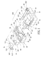
- the first preferred embodiment of the padlock of the present invention is shown to include a U-shaped lock casing 200, a key-operated lock core unit 400, a shackle bar 24, and a catch member 50.
- the lock casing 200 includes a first casing part 20 and a second casing part 30 secured to the first casing part 20.
- the first casing part 20 has a first end surface 23, a lock core mounting portion 210 extending from the first end surface 23 in a longitudinal direction, and a first shackle mounting portion 25 extending from the lock core mounting portion 210 in a first transverse direction transverse to the longitudinal direction.
- the lock core mounting portion 210 has an insert end 22 opposite to the first end surface 23.
- the lock core mounting portion 210 is formed with a core receiving space 21 that extends in the longitudinal direction from the first end surface 23 through the insert end 22.
- the first shackle mounting portion 25 is formed with a blind first shackle insert hole 251 which is provided with a biasing spring 252 therein.
- the second casing part 30 has a second end surface 38 which is opposite to the first end surface 23 of the first casing part 20 in the longitudinal direction, a latch receiving portion 310 adjacent to the second end surface 38, and a second shackle mounting portion 34 that extends from the latch receiving portion 310 in the first transverse direction.
- the latch receiving portion 310 is formed with a latch recess 31 and a latch entrance 33 which is communicated with the latch recess 31 and which receives fittingly the insert end 22 of the lock core mounting portion 210 such that the latch recess 31 is communicated with the core receiving space 21.
- the latch entrance 33 has a confining wall which is formed with a latch passage 312 that extends in the longitudinal direction from the latch recess 31 to the core receiving space 21.
- the latch receiving portion 310 is welded to the insert end 22 of the lock core mounting portion 210 of the first casing part 20.
- the latch receiving portion 310 has a confiningwall which confines the latch recess 31 and the latch entrance 33.
- the confiningwall has an access hole 313 formed therethrough, a curved inner surface part 32, a slide groove 37 that extends in the first transverse direction, and a latch passage 312 that is formed in the latch entrance 33 and that extends in the longitudinal direction between the latch recess 31 and the core receiving space 21.
- the second shackle mounting portion 34 is opposite to the first shackle mounting portion 25 in the longitudinal direction, and has a second shackle insert hole 35 formed therethrough.
- the second shackle insert hole 35 extends in the longitudinal direction, and is aligned with the first shackle insert hole 251.
- the second shackle insert hole 35 has an inner surface formed with a retaining shoulder 351 that confronts the first shackle mounting portion 25.
- the second lock casing 30 is further formed with a slide channel 36 that extends in the first transverse direction to communicate the second shackle insert hole 35 with the latch recess 31.
- the lock core unit 400 includes a cylindrical lock core 43 formed with a keyhole 430 and disposed in the core receiving space 21.
- the lock core 43 is adapted to be rotated inside the core receiving space 21 upon insertion of a corresponding key (not shown) into the keyhole 430.
- the lock core 43 has one end 431 disposed adjacent to the insert end 22 of the lock core mounting portion 210.
- the lock core unit 400 further includes a latch member 40 connected to the end 431 of the lock core 43 and extending out of the core receiving space 21.
- the latch member 40 extends into the latch recess 31, and is rotatable inside the latch recess 31 between locking and unlocking positions when the corresponding key is operated.
- the latch member 40 includes a latch base 41 coupled to the end 431 of the lock core 43 and formed with a slide cavity 410 that extends in a second transverse direction transverse to the longitudinal direction, a latch body 42 mounted on the latch base 41 inside the slide cavity 410, and a biasing spring 413 for biasing the latch body 42 to extend outwardly of the slide cavity 410 and to project from the latch base 41 in the second transverse direction so as to enable the latch body 42 to engage the confining wall of the latch receiving portion 310.
- the latch base 41 has a convex outer wall surface 412.
- the shackle bar 24 is an elongate straight bar, and has a first end 241 which extends removably into the first shackle insert hole 251 and which is formed with an abutment shoulder 242 confronting the second shackle mounting portion 34, and a second end 243 which extends through the second shackle insert hole 35 and which is formed with a shackle groove 244.
- the catch member 50 is disposed in the latch recess 31, and is slidable along the slide groove 37.
- the catch member 50 includes a first catch body 51, and a second catch body 52 connected to the first catch body 51.
- the first catch body 51 has a first abutment wall 515, a shackle engaging projection 511 projecting from the first abutment wall 515 in the first transverse direction and extending into the slide channel 36, and a first connecting wall 512 extending from the first abutment wall 515 opposite to the shackle engaging portion 511.
- the first connecting wall 512 is formed with an engaging stud 513.
- the first abutment wall 515 and the shackle engaging projection 511 constitute a first end portion 51a of the catch member 50.
- the second catch member 52 includes a second abutment wall 521 which is opposite to the first abutment wall 515 in the first transverse direction, and which is spaced-apart from and parallel to the first abutment wall 515, and a second connecting wall 522 which extends from the second abutment wall 521 in the first transverse direction toward the first catch body 51.
- the second connecting wall 522 is formed with an engaging hole 523 for engaging the engaging stud 513 of the first catch body 51 such that the second catch body 52 is slidable together with the first catch body 51 in the first transverse direction along the slide groove 37.
- the second abutment wall 521 constitutes a second end portion of the catch member 50 opposite to the first end portion 51a.
- a latch cavity 53 is defined between the first and second abutment walls 515, 521 to permit extension of the latch member 40 thereinto.
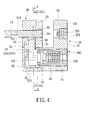
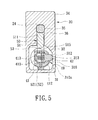
- the latch body 42 When the latch member 40 is disposed in the locking position, the latch body 42 abuts against and pushes the first abutment wall 515 of the first catch body 51 to cause the first and second catch bodies 51, 52 to slide along the slide groove 37 toward the second shackle mounting portion 34 so as to enable the shackle engaging projection 511 to project into the second shackle insert hole 35 and engage the shackle groove 244 in the second end 243 of the shackle bar 24.
- the key is inserted into the keyhole 430 to rotate the lock core 43 and cause rotation of the latch member 40 to the unlocking position.
- the latch body 42 slides along the curved wall 32, and is pushed by the curved wall 32 to extend inwardly and partly into the slide cavity 410 against biasing action of the biasing spring 413.
- the convex outer wall surface 412 of the latch base 41 abuts against and pushes the second abutment wall 521 of the second catch body 52 to cause the first and second catch bodies 51, 52 to slide along the slide groove 37 in a direction away from the second shackle mounting portion 34 so as to enable the shackle engaging projection 511 to retract into the slide channel 36 and disengage from the shackle bar 24.
- the shackle bar 24 is thus moved in the longitudinal direction away from the first shackle mounting portion 25 for removing the first end 241 thereof from the first shackle insert hole 251 due to the biasing action of the biasing spring 252 provided in the first shackle insert hole 251.
- the abutment shoulder 242 at the first end 241 of the shackle bar 24 abuts against the retaining shoulder 351 in the second shackle insert hole 35 to prevent removal of the shackle bar 24 from the second shackle insert hole 35.
- the latch body 42 engages an inner wall surface 312a of the confining wall of the latch receiving portion 310, and is thus prevented from being removed from the latch receiving portion 310 along the longitudinal direction via the latch entrance 33.
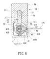
- the latch body 42 is registered with the access hole 312, and is accessible by a tool 100 that extends into the access hole 312. By retracting the latch body 42 into the slide cavity 410 using the tool 100, the latch body 42 can be disengaged from the inner wall surface of the confining wall 310a.
- the latch body 2 is movable along the latch passage 312 to permit removal of the latch member 40 from the latch recess 31, and the latch member 40 has a size sufficient for retraction into the core receiving space 21 of the first lock casing 20 and for removal of the lock core unit 400 from the core receiving space 21.
- the lock core unit 400 can be replaced with a new set when damaged, such as in the event of spring fatigue.
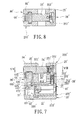
- the second preferred embodiment of the padlock according to the present invention similarly includes a U-shaped lock casing with first and second casing parts 20', 30'.
- the first casing part 20' has a lock core mounting portion 210' formed with a core receiving space 21', and a first shackle mounting portion 25' that extends from the lock core mounting portion 210' and that is formed with a blind first shackle insert hole 251'.
- the second casing part 30' has a latch receiving portion 310' connected to the lock core mounting portion 210' and formed with a latch recess 31', and a second shackle mounting portion 34' that extends from the latch receiving portion 310' and that opposes the first shackle mounting portion 25'.
- the second shackle mounting portion 34' is formed with a second shackle insert hole 35' aligned with the first shackle insert hole 251'.
- a lock core unit 400' is received in the core receiving space 21', and is coupled to a latch member 42' which is disposed rotatably inside the latch recess 31'.
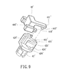
- the latch member 42' has a distal end face 421' transverse to an axis of the lock core unit 400', and a side wall 425' transverse to the distal end face 421'.
- the distal end face 421' is formed with a pin hole 422' that is eccentric to the axis of the lock core unit 400'.
- the side wall 425' is formed with a slide slot 424' that extends along a plane parallel to the end face 421', and a communicating hole 423' that extends parallel to the axis of the lock core unit 400' from the end face 421' to the slide slot 424'.
- the side wall 425' is formed with a stop flange 26' between the slide slot 424' and the end face 421'.
- the latch member 42' engages a catch member 44' that is disposed in the latch recess 31'.
- the catch member 44' has a first end portion 445' extending into a slide channel 36' that intercommunicates the latch recess 31' and the second shackle insert hole 35', and a second end portion 441' formed with a cylindrical pin 442' that extends rotatably into the pin hole 422' for engaging the latch member 42'.
- the catch member 44' is further formed with a stop projection 443' which extends from the first end portion 445' toward the second end portion 441' and which extends into the slide slot 424' via the communicating hole 423'.
- a lock core retainer 26' is received in a receiving cavity 252' in the first shackle mounting portion 25' and communicated with the core receiving space 21'.
- the first shackle mounting portion 25' has a side wall which confronts the second shackle mounting portion 34' and which is formed with a through hole 231' that is communicated with the receiving cavity 252'.
- the through hole 231' is concealed by an article that is locked on the padlock.
- the lock core retainer 26' includes a retaining shaft 260' and a biasing spring 262' for biasing the retaining shaft 260' to project into the core receiving space 21' for engaging a retaining groove 45' formed in an outer wall surface of the lock core unit 400' so as to retain the lock core unit 400' in the lock core mounting portion 210'.
- the retaining shaft 260' has an outer surface formed with a groove 261'.
- the shackle bar 24' has a first end adjacent to the first shackle insert hole 251' and provided with an abutment unit which is in the form of a spring-loaded ball member 352' for engaging a retaining shoulder 351' within the second shackle insert hole 35' so as to prevent removal of the shackle bar 24' from the second shackle insert hole 35' and thus the lock casing 200'.
- the stop flange 443' is registered with the communicating hole 423' to permit removal of the latch member 42' from the catch member 44'.
- the latch member 42' is first moved to the unlocking position and the article is removed from the padlock.
- a tool (not shown) is extended into a space between the first and second shackle mounting portions 34', 25', and into the receiving cavity 252' via the through hole 231' for engaging the groove 261' of the retaining shaft 260' so as to retract the retaining shaft 260' into the receiving cavity 252', thereby disengaging the retaining shaft 260' from the retaining groove 45' of the lock core unit 400'.
- the lock core unit 400' is thus removable from the core receiving space 21' at this time.
Landscapes
- Lock And Its Accessories (AREA)
- Refuge Islands, Traffic Blockers, Or Guard Fence (AREA)
- Supports Or Holders For Household Use (AREA)
- Bag Frames (AREA)
Priority Applications (3)
| Application Number | Priority Date | Filing Date | Title |
|---|---|---|---|
| EP01308848A EP1304434B1 (fr) | 2001-10-18 | 2001-10-18 | Cadenas avec un boîtier de serrure en forme de U |
| AT01308848T ATE329109T1 (de) | 2001-10-18 | 2001-10-18 | Vorhängeschloss mit einem u-förmigen schlossgehäuse |
| DE60120412T DE60120412T2 (de) | 2001-10-18 | 2001-10-18 | Vorhängeschloss mit einem U-förmigen Schlossgehäuse |
Applications Claiming Priority (1)
| Application Number | Priority Date | Filing Date | Title |
|---|---|---|---|
| EP01308848A EP1304434B1 (fr) | 2001-10-18 | 2001-10-18 | Cadenas avec un boîtier de serrure en forme de U |
Publications (2)
| Publication Number | Publication Date |
|---|---|
| EP1304434A1 true EP1304434A1 (fr) | 2003-04-23 |
| EP1304434B1 EP1304434B1 (fr) | 2006-06-07 |
Family
ID=8182371
Family Applications (1)
| Application Number | Title | Priority Date | Filing Date |
|---|---|---|---|
| EP01308848A Expired - Lifetime EP1304434B1 (fr) | 2001-10-18 | 2001-10-18 | Cadenas avec un boîtier de serrure en forme de U |
Country Status (3)
| Country | Link |
|---|---|
| EP (1) | EP1304434B1 (fr) |
| AT (1) | ATE329109T1 (fr) |
| DE (1) | DE60120412T2 (fr) |
Cited By (4)
| Publication number | Priority date | Publication date | Assignee | Title |
|---|---|---|---|---|
| CZ307179B6 (cs) * | 2017-01-10 | 2018-02-21 | UrbanAlps Czech s.r.o. | Visací zámek |
| CN109930918A (zh) * | 2019-04-15 | 2019-06-25 | 珠海优特电力科技股份有限公司 | 挂锁、挂锁解锁方法和挂锁闭锁方法 |
| CN112539004A (zh) * | 2020-12-10 | 2021-03-23 | 潘永旺 | U型锁 |
| RU2766460C1 (ru) * | 2021-07-26 | 2022-03-15 | Александр Иванович Худолий | Бездужковый висячий замок |
Citations (7)
| Publication number | Priority date | Publication date | Assignee | Title |
|---|---|---|---|---|
| US2104981A (en) * | 1936-11-06 | 1938-01-11 | Independent Lock Co | Lock |
| GB550596A (en) * | 1941-08-30 | 1943-01-15 | Yale & Towne Mfg Co | Improvements in and relating to padlock cylinder retainers |
| FR953722A (fr) * | 1947-02-04 | 1949-12-12 | Cadenas | |
| GB1218128A (en) * | 1967-11-18 | 1971-01-06 | Viro Innocenti Spa | Improvements in or relating to padlocks |
| US3820283A (en) * | 1972-09-14 | 1974-06-28 | J Shramovich | Locking system and lock therefor |
| US5987939A (en) * | 1998-10-07 | 1999-11-23 | Solex International (Thailand) Co., Ltd. | Padlock for use with steel grilles |
| EP0964123A1 (fr) * | 1997-10-03 | 1999-12-15 | Waterson Chen | Cadenas à barillet interchangeable actionné par une clé |
Family Cites Families (1)
| Publication number | Priority date | Publication date | Assignee | Title |
|---|---|---|---|---|
| AU750069B1 (en) * | 2001-07-23 | 2002-07-11 | Waterson Chen | Impact resistant lock apparatus with anti-theft lock core |
-
2001
- 2001-10-18 AT AT01308848T patent/ATE329109T1/de not_active IP Right Cessation
- 2001-10-18 DE DE60120412T patent/DE60120412T2/de not_active Expired - Fee Related
- 2001-10-18 EP EP01308848A patent/EP1304434B1/fr not_active Expired - Lifetime
Patent Citations (7)
| Publication number | Priority date | Publication date | Assignee | Title |
|---|---|---|---|---|
| US2104981A (en) * | 1936-11-06 | 1938-01-11 | Independent Lock Co | Lock |
| GB550596A (en) * | 1941-08-30 | 1943-01-15 | Yale & Towne Mfg Co | Improvements in and relating to padlock cylinder retainers |
| FR953722A (fr) * | 1947-02-04 | 1949-12-12 | Cadenas | |
| GB1218128A (en) * | 1967-11-18 | 1971-01-06 | Viro Innocenti Spa | Improvements in or relating to padlocks |
| US3820283A (en) * | 1972-09-14 | 1974-06-28 | J Shramovich | Locking system and lock therefor |
| EP0964123A1 (fr) * | 1997-10-03 | 1999-12-15 | Waterson Chen | Cadenas à barillet interchangeable actionné par une clé |
| US5987939A (en) * | 1998-10-07 | 1999-11-23 | Solex International (Thailand) Co., Ltd. | Padlock for use with steel grilles |
Cited By (6)
| Publication number | Priority date | Publication date | Assignee | Title |
|---|---|---|---|---|
| CZ307179B6 (cs) * | 2017-01-10 | 2018-02-21 | UrbanAlps Czech s.r.o. | Visací zámek |
| CN109930918A (zh) * | 2019-04-15 | 2019-06-25 | 珠海优特电力科技股份有限公司 | 挂锁、挂锁解锁方法和挂锁闭锁方法 |
| CN109930918B (zh) * | 2019-04-15 | 2023-07-25 | 珠海优特电力科技股份有限公司 | 挂锁、挂锁解锁方法和挂锁闭锁方法 |
| CN112539004A (zh) * | 2020-12-10 | 2021-03-23 | 潘永旺 | U型锁 |
| CN112539004B (zh) * | 2020-12-10 | 2023-01-31 | 潘永旺 | U型锁 |
| RU2766460C1 (ru) * | 2021-07-26 | 2022-03-15 | Александр Иванович Худолий | Бездужковый висячий замок |
Also Published As
| Publication number | Publication date |
|---|---|
| DE60120412D1 (de) | 2006-07-20 |
| ATE329109T1 (de) | 2006-06-15 |
| EP1304434B1 (fr) | 2006-06-07 |
| DE60120412T2 (de) | 2006-10-19 |
Similar Documents
| Publication | Publication Date | Title |
|---|---|---|
| US6553801B2 (en) | Impact resistant lock apparatus with anti-theft lock core | |
| US7174756B2 (en) | Padlock | |
| US6453706B1 (en) | Padlock with a U-shaped lock casing | |
| US6351976B1 (en) | Door lock assembly | |
| EP2942456B1 (fr) | Serrure antivol | |
| US20080011033A1 (en) | Reset fixture for rekeyable lock assembly | |
| CN101529036A (zh) | 安装型保险装置 | |
| CA2495269A1 (fr) | Ensemble serrure a possibilite de changement de cle et procede de fonctionnement | |
| US20090151407A1 (en) | Door lock with automatic locking of deadbolt | |
| EP3653813A1 (fr) | Verrou ayant un pêne dormant à longue course | |
| US6408661B1 (en) | Padlock assembly with a two-part U-shaped lock casing | |
| US7437899B1 (en) | Suitcase lock assembly | |
| US4083211A (en) | Axial split-pin tumbler-type lock mechanism for a handle lock | |
| US6919797B2 (en) | Remote-controlled lock | |
| US6574999B2 (en) | Padlock with a U-shaped lock casing | |
| EP1304434A1 (fr) | Cadenas avec un boítier de serrure en forme de U | |
| US7162900B1 (en) | Tubular lock and master key | |
| EP1365091A1 (fr) | Cadenas à barillet interchangeable avec maillon de liaison flexible interchangeable | |
| EP0090620B1 (fr) | Serrure démontable par devant | |
| EP3653816A1 (fr) | Verrou comportant des modules remplaçables | |
| US7475579B2 (en) | Lock with a limiting slide assembly | |
| US20010039818A1 (en) | Pad lock | |
| EP3653815A1 (fr) | Verrou doté d'une fonction de déverrouillage d'urgence | |
| US7555925B1 (en) | Padlock | |
| JP4127702B2 (ja) | 南京錠 |
Legal Events
| Date | Code | Title | Description |
|---|---|---|---|
| PUAI | Public reference made under article 153(3) epc to a published international application that has entered the european phase |
Free format text: ORIGINAL CODE: 0009012 |
|
| AK | Designated contracting states |
Designated state(s): AT BE CH CY DE DK ES FI FR GB GR IE IT LI LU MC NL PT SE TR |
|
| AX | Request for extension of the european patent |
Extension state: AL LT LV MK RO SI |
|
| 17P | Request for examination filed |
Effective date: 20030820 |
|
| AKX | Designation fees paid |
Designated state(s): AT BE CH CY DE DK ES FI FR GB GR IE IT LI LU MC NL PT SE TR |
|
| 17Q | First examination report despatched |
Effective date: 20040220 |
|
| GRAP | Despatch of communication of intention to grant a patent |
Free format text: ORIGINAL CODE: EPIDOSNIGR1 |
|
| GRAS | Grant fee paid |
Free format text: ORIGINAL CODE: EPIDOSNIGR3 |
|
| GRAA | (expected) grant |
Free format text: ORIGINAL CODE: 0009210 |
|
| AK | Designated contracting states |
Kind code of ref document: B1 Designated state(s): AT BE CH CY DE DK ES FI FR GB GR IE IT LI LU MC NL PT SE TR |
|
| PG25 | Lapsed in a contracting state [announced via postgrant information from national office to epo] |
Ref country code: IT Free format text: LAPSE BECAUSE OF FAILURE TO SUBMIT A TRANSLATION OF THE DESCRIPTION OR TO PAY THE FEE WITHIN THE PRESCRIBED TIME-LIMIT;WARNING: LAPSES OF ITALIAN PATENTS WITH EFFECTIVE DATE BEFORE 2007 MAY HAVE OCCURRED AT ANY TIME BEFORE 2007. THE CORRECT EFFECTIVE DATE MAY BE DIFFERENT FROM THE ONE RECORDED. Effective date: 20060607 Ref country code: FI Free format text: LAPSE BECAUSE OF FAILURE TO SUBMIT A TRANSLATION OF THE DESCRIPTION OR TO PAY THE FEE WITHIN THE PRESCRIBED TIME-LIMIT Effective date: 20060607 Ref country code: CH Free format text: LAPSE BECAUSE OF FAILURE TO SUBMIT A TRANSLATION OF THE DESCRIPTION OR TO PAY THE FEE WITHIN THE PRESCRIBED TIME-LIMIT Effective date: 20060607 Ref country code: BE Free format text: LAPSE BECAUSE OF FAILURE TO SUBMIT A TRANSLATION OF THE DESCRIPTION OR TO PAY THE FEE WITHIN THE PRESCRIBED TIME-LIMIT Effective date: 20060607 Ref country code: AT Free format text: LAPSE BECAUSE OF FAILURE TO SUBMIT A TRANSLATION OF THE DESCRIPTION OR TO PAY THE FEE WITHIN THE PRESCRIBED TIME-LIMIT Effective date: 20060607 Ref country code: LI Free format text: LAPSE BECAUSE OF FAILURE TO SUBMIT A TRANSLATION OF THE DESCRIPTION OR TO PAY THE FEE WITHIN THE PRESCRIBED TIME-LIMIT Effective date: 20060607 Ref country code: NL Free format text: LAPSE BECAUSE OF FAILURE TO SUBMIT A TRANSLATION OF THE DESCRIPTION OR TO PAY THE FEE WITHIN THE PRESCRIBED TIME-LIMIT Effective date: 20060607 |
|
| REG | Reference to a national code |
Ref country code: GB Ref legal event code: FG4D |
|
| REG | Reference to a national code |
Ref country code: CH Ref legal event code: EP |
|
| REG | Reference to a national code |
Ref country code: IE Ref legal event code: FG4D |
|
| REF | Corresponds to: |
Ref document number: 60120412 Country of ref document: DE Date of ref document: 20060720 Kind code of ref document: P |
|
| PG25 | Lapsed in a contracting state [announced via postgrant information from national office to epo] |
Ref country code: SE Free format text: LAPSE BECAUSE OF FAILURE TO SUBMIT A TRANSLATION OF THE DESCRIPTION OR TO PAY THE FEE WITHIN THE PRESCRIBED TIME-LIMIT Effective date: 20060907 Ref country code: DK Free format text: LAPSE BECAUSE OF FAILURE TO SUBMIT A TRANSLATION OF THE DESCRIPTION OR TO PAY THE FEE WITHIN THE PRESCRIBED TIME-LIMIT Effective date: 20060907 |
|
| PG25 | Lapsed in a contracting state [announced via postgrant information from national office to epo] |
Ref country code: ES Free format text: LAPSE BECAUSE OF FAILURE TO SUBMIT A TRANSLATION OF THE DESCRIPTION OR TO PAY THE FEE WITHIN THE PRESCRIBED TIME-LIMIT Effective date: 20060918 |
|
| PG25 | Lapsed in a contracting state [announced via postgrant information from national office to epo] |
Ref country code: IE Free format text: LAPSE BECAUSE OF NON-PAYMENT OF DUE FEES Effective date: 20061018 |
|
| PGFP | Annual fee paid to national office [announced via postgrant information from national office to epo] |
Ref country code: GB Payment date: 20061019 Year of fee payment: 6 |
|
| PGFP | Annual fee paid to national office [announced via postgrant information from national office to epo] |
Ref country code: DE Payment date: 20061030 Year of fee payment: 6 |
|
| PG25 | Lapsed in a contracting state [announced via postgrant information from national office to epo] |
Ref country code: MC Free format text: LAPSE BECAUSE OF NON-PAYMENT OF DUE FEES Effective date: 20061031 |
|
| PG25 | Lapsed in a contracting state [announced via postgrant information from national office to epo] |
Ref country code: PT Free format text: LAPSE BECAUSE OF FAILURE TO SUBMIT A TRANSLATION OF THE DESCRIPTION OR TO PAY THE FEE WITHIN THE PRESCRIBED TIME-LIMIT Effective date: 20061107 |
|
| PGFP | Annual fee paid to national office [announced via postgrant information from national office to epo] |
Ref country code: FR Payment date: 20061110 Year of fee payment: 6 |
|
| ET | Fr: translation filed | ||
| NLV1 | Nl: lapsed or annulled due to failure to fulfill the requirements of art. 29p and 29m of the patents act | ||
| REG | Reference to a national code |
Ref country code: CH Ref legal event code: PL |
|
| PLBE | No opposition filed within time limit |
Free format text: ORIGINAL CODE: 0009261 |
|
| STAA | Information on the status of an ep patent application or granted ep patent |
Free format text: STATUS: NO OPPOSITION FILED WITHIN TIME LIMIT |
|
| 26N | No opposition filed |
Effective date: 20070308 |
|
| PG25 | Lapsed in a contracting state [announced via postgrant information from national office to epo] |
Ref country code: GR Free format text: LAPSE BECAUSE OF FAILURE TO SUBMIT A TRANSLATION OF THE DESCRIPTION OR TO PAY THE FEE WITHIN THE PRESCRIBED TIME-LIMIT Effective date: 20060908 |
|
| GBPC | Gb: european patent ceased through non-payment of renewal fee |
Effective date: 20071018 |
|
| PG25 | Lapsed in a contracting state [announced via postgrant information from national office to epo] |
Ref country code: DE Free format text: LAPSE BECAUSE OF NON-PAYMENT OF DUE FEES Effective date: 20080501 Ref country code: LU Free format text: LAPSE BECAUSE OF NON-PAYMENT OF DUE FEES Effective date: 20061018 Ref country code: TR Free format text: LAPSE BECAUSE OF FAILURE TO SUBMIT A TRANSLATION OF THE DESCRIPTION OR TO PAY THE FEE WITHIN THE PRESCRIBED TIME-LIMIT Effective date: 20060607 |
|
| REG | Reference to a national code |
Ref country code: FR Ref legal event code: ST Effective date: 20080630 |
|
| PG25 | Lapsed in a contracting state [announced via postgrant information from national office to epo] |
Ref country code: GB Free format text: LAPSE BECAUSE OF NON-PAYMENT OF DUE FEES Effective date: 20071018 Ref country code: CY Free format text: LAPSE BECAUSE OF FAILURE TO SUBMIT A TRANSLATION OF THE DESCRIPTION OR TO PAY THE FEE WITHIN THE PRESCRIBED TIME-LIMIT Effective date: 20060607 |
|
| PG25 | Lapsed in a contracting state [announced via postgrant information from national office to epo] |
Ref country code: FR Free format text: LAPSE BECAUSE OF NON-PAYMENT OF DUE FEES Effective date: 20071031 |