EP1304531A1 - Luftauslass - Google Patents
Luftauslass Download PDFInfo
- Publication number
- EP1304531A1 EP1304531A1 EP02022050A EP02022050A EP1304531A1 EP 1304531 A1 EP1304531 A1 EP 1304531A1 EP 02022050 A EP02022050 A EP 02022050A EP 02022050 A EP02022050 A EP 02022050A EP 1304531 A1 EP1304531 A1 EP 1304531A1
- Authority
- EP
- European Patent Office
- Prior art keywords
- air outlet
- air
- jacket
- cover
- outlet according
- Prior art date
- Legal status (The legal status is an assumption and is not a legal conclusion. Google has not performed a legal analysis and makes no representation as to the accuracy of the status listed.)
- Granted
Links
- 230000004313 glare Effects 0.000 description 3
- 238000001816 cooling Methods 0.000 description 2
- 239000000203 mixture Substances 0.000 description 2
- 238000010438 heat treatment Methods 0.000 description 1
Images


Classifications
-
- F—MECHANICAL ENGINEERING; LIGHTING; HEATING; WEAPONS; BLASTING
- F24—HEATING; RANGES; VENTILATING
- F24F—AIR-CONDITIONING; AIR-HUMIDIFICATION; VENTILATION; USE OF AIR CURRENTS FOR SCREENING
- F24F13/00—Details common to, or for air-conditioning, air-humidification, ventilation or use of air currents for screening
- F24F13/02—Ducting arrangements
- F24F13/06—Outlets for directing or distributing air into rooms or spaces, e.g. ceiling air diffuser
- F24F13/068—Outlets for directing or distributing air into rooms or spaces, e.g. ceiling air diffuser formed as perforated walls, ceilings or floors
Definitions
- the present invention relates to a Air outlet for connection to an air duct system with a jacket which has recesses and in which at least one blind ring is arranged.
- the object of the present invention is the above to improve known air outlets in that a finer adjustment of the air supply is possible.
- part of the mantle is provided with a cover.
- This cover ensures that the air passes through cannot penetrate the covered part, but escapes sideways. A person who is in front of the Cover stops, only indirectly gets air, and that through the recesses of the jacket that are not through the Cover are covered.
- the cover can be arranged adjustable on the jacket can be done by one person as desired can be set.
- Such a cover can still be chosen that they are, for example, only part of the coat covers or only part of the jacket on the one hand its axis.
- the air distribution can by the design of the Jacket in connection with the cover further to be influenced.
- the coat can be made of different Sections exist which are the same size or also have recesses of different sizes.
- the coat can also be a simple perforated sheet jacket. Be here there are no limits to the invention.
- the air supply can additionally by one or more, optionally rotatable and / or displaceable blind rings be distracted, which is placed inside the mantle are.
- the shape and arrangement of the Glare rings set no limits.
- an adjustable flap that is inside the jacket can be arranged above the cover. This The adjustment flap can be turned using a rotary lever.
- a cable adjustment can also be used be provided, by means of which the adjustment flap is rotated becomes.
- Other corresponding devices are conceivable.
- the adjustment flap is in the vertical position, then the air can flow past unhindered exit at the bottom. However, the adjustment flap is in horizontal position, so is in front of the adjustment flap Air build-up creates and the air flows horizontally Direction outwards or even diagonally upwards.
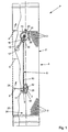
- an air outlet P has a jacket 1, which has an area 2 which has recesses 3 is provided.
- blind rings 4 and 5 Inside the casing 1 there are two blind rings 4 and 5 arranged, which may be rotatable and / or displaceable are.
- Adjustment flap 6 arranged, which over a Stub shaft 7 is connected to a rotating device 8.
- This rotating device 8 has at its lower end Articulation 9, via which a linkage 10 with a lever 11 connected is. At the other end of the joint 9 is the lever 11 with a bolt 12 in a curved slot 13 guided. This slot 13 determines the path of rotation Stub shaft 7 and thus the adjustment flap 6.
- the stub shaft 7 and the slot 13 are both in one Bracket 14 is provided, which is arranged on the jacket 1 is.
- the rotating device 8 has one Rotary lever 15, which with another joint 16 with the upper end of the linkage 10 is connected.
- the Rotary lever 15 is at one end with a knob 17th provided which better handling of the rotary lever 15th allows.
- the other end of the rotary lever 15 is in one Sleeve 18 which is attached to a turntable 18.
- This turntable 19 rotates about an axis 20 on one Bracket 21, which in turn by means of fasteners 22 is attached to the jacket 1.
- the adjustment flap 6 is over the shaft end 7 and one further stub shaft 29 also rotatably supported, wherein a stop 30 is provided, which is an end position of the Adjustment flap 6 determines.
- the former is achieved when the rotary lever 15 is down is rotated and the adjustment flap 6 is consequently closed is.
- the air then flows evenly on all sides horizontally, diagonally downwards or diagonally upwards.
Landscapes
- Engineering & Computer Science (AREA)
- Chemical & Material Sciences (AREA)
- Combustion & Propulsion (AREA)
- Mechanical Engineering (AREA)
- General Engineering & Computer Science (AREA)
- Air-Flow Control Members (AREA)
- Respiratory Apparatuses And Protective Means (AREA)
- Sampling And Sample Adjustment (AREA)
Abstract
Description
| Positionszahlenliste | |||||
| 1 | Mantel | 34 | 67 | ||
| 2 | Bereich | 35 | 68 | ||
| 3 | Ausnehmung | 36 | 69 | ||
| 4 | Blendring | 37 | 70 | ||
| 5 | Blendring | 38 | 71 | ||
| 6 | Verstellklappe | 39 | 72 | ||
| 7 | Wellenstummel | 40 | 73 | ||
| 8 | Drehvorrichtung | 41 | 74 | ||
| 9 | Gelenk | 42 | 75 | ||
| 10 | Gestänge | 43 | 76 | ||
| 11 | Hebel | 44 | 77 | ||
| 12 | Bolzen | 45 | 78 | ||
| 13 | Langloch | 46 | 79 | ||
| 14 | Halterung | 47 | |||
| 15 | Drehhebel | 48 | |||
| 16 | Gelenk | 49 | |||
| 17 | Knauf | 50 | P | Luftauslass | |
| 18 | Hülse | 51 | |||
| 19 | Drehscheibe | 52 | |||
| 20 | Achse | 53 | |||
| 21 | Halterung | 54 | |||
| 22 | Befestigungselem. | 55 | |||
| 23 | Abdeckung | 56 | |||
| 24 | Befestigungselem. | 57 | |||
| 25 | Befestigungselem. | 58 | |||
| 26 | Befestigungselem. | 59 | |||
| 27 | Anschlag | 60 | |||
| 28 | Anschlag | 61 | |||
| 29 | Wellenstummel | 62 | |||
| 30 | Anschlag | 63 | |||
| 31 | 64 | ||||
| 32 | 65 | ||||
| 33 | 66 |
Claims (11)
- Luftauslass zum Anschliessen an ein Luftführungssystem mit einem Mantel (1), der Ausnehmungen (3) aufweist und in dem zumindest ein Blendring (4, 5) angeordnet ist,
dadurch gekennzeichnet, dass ein Teil des Mantels (1) mit einer Abdeckung (23) versehen ist. - Luftauslass nach Anspruch 1, dadurch gekennzeichnet, dass die Abdeckung (23) auf dem Mantel (1) verstellbar angeordnet ist.
- Luftauslass nach Anspruch 1 oder 2, dadurch gekennzeichnet, dass die Abdeckung (23) nur einen Teil des Mantels (1) einerseits einer Achse abdeckt.
- Luftauslass nach einem der Ansprüche 1 bis 3, dadurch gekennzeichnet, dass der Mantel (1) aus verschiedenen Abschnitten besteht, welche die Ausnehmungen (3) aufweisen.
- Luftauslass nach Anspruch 1, dadurch gekennzeichnet, dass zumindest ein Blendring (4, 5) drehbar angeordnet ist.
- Luftauslass nach wenigstens einem der Ansprüche 1 bis 5, dadurch gekennzeichnet, dass der zumindest eine Blendring (4, 5) in Inneren des Mantels (1) versetzbar angeordnet ist.
- Luftauslass nach wenigstens einem der Ansprüche 1 bis 6, dadurch gekennzeichnet, dass eine Verstellklappe (6) im Inneren des Mantels (1) vorgesehen ist.
- Luftauslass nach Anspruch 7, dadurch gekennzeichnet, dass die Verstellklappe (6) über der Abdeckung (23) angeordnet ist.
- Luftauslass nach Anspruch 7 oder 8, dadurch gekennzeichnet, dass die Verstellklappe (6) drehbar angeordnet ist.
- Luftauslass nach Anspruch 9, dadurch gekennzeichnet, dass ein Wellenstummel (7) an der Verstellklappe (6) von einem Drehhebel (15) betätigbar ist.
- Luftauslass nach Anspruch 10, dadurch gekennzeichnet, dass der Drehweg des Wellenstummels (7) begrenzt ist.
Priority Applications (1)
| Application Number | Priority Date | Filing Date | Title |
|---|---|---|---|
| DK02022050T DK1304531T3 (da) | 2001-10-10 | 2002-10-02 | Luftudgang |
Applications Claiming Priority (2)
| Application Number | Priority Date | Filing Date | Title |
|---|---|---|---|
| DE10149909 | 2001-10-10 | ||
| DE10149909A DE10149909B4 (de) | 2001-10-10 | 2001-10-10 | Luftauslass |
Publications (2)
| Publication Number | Publication Date |
|---|---|
| EP1304531A1 true EP1304531A1 (de) | 2003-04-23 |
| EP1304531B1 EP1304531B1 (de) | 2005-07-27 |
Family
ID=7701999
Family Applications (1)
| Application Number | Title | Priority Date | Filing Date |
|---|---|---|---|
| EP02022050A Expired - Lifetime EP1304531B1 (de) | 2001-10-10 | 2002-10-02 | Luftauslass |
Country Status (5)
| Country | Link |
|---|---|
| EP (1) | EP1304531B1 (de) |
| AT (1) | ATE300708T1 (de) |
| DE (2) | DE10149909B4 (de) |
| DK (1) | DK1304531T3 (de) |
| ES (1) | ES2241940T3 (de) |
Citations (6)
| Publication number | Priority date | Publication date | Assignee | Title |
|---|---|---|---|---|
| DE3429710A1 (de) | 1984-08-11 | 1986-02-13 | Turbon-Tunzini Klimatechnik GmbH, 5060 Bergisch Gladbach | Luftauslass mit einem zylindrischen mantel |
| DE3521661A1 (de) * | 1985-06-18 | 1986-12-18 | Mayer, Georg, Dipl.-Ing., 1000 Berlin | Vorrichtung zur veraenderung der geometrie eines lochblechluftauslasses |
| EP0269923A2 (de) * | 1986-11-29 | 1988-06-08 | Kessler & Luch GmbH | Quelluftauslass |
| DE3918218A1 (de) | 1989-06-03 | 1990-12-06 | Turbon Tunzini Klimatechnik | Luftauslass |
| US5033362A (en) * | 1990-08-30 | 1991-07-23 | James E. Huckestein Inc. | Air distribution outlet |
| US5360373A (en) * | 1993-01-08 | 1994-11-01 | H. Krantz-Tkt Gmbh | Upwelling-air distributor for air-conditioning systems |
Family Cites Families (3)
| Publication number | Priority date | Publication date | Assignee | Title |
|---|---|---|---|---|
| DE4122432A1 (de) * | 1991-07-06 | 1991-11-07 | Ltg Lufttechnische Gmbh | Industrieluftauslass zum heizen oder kuehlen |
| DE4210807C2 (de) * | 1992-04-01 | 1995-06-14 | Siegle & Epple | Luftdurchlaß |
| DE20018608U1 (de) * | 2000-10-31 | 2001-01-25 | EMCO Klima GmbH & Co. KG, 49808 Lingen | Luftauslaß |
-
2001
- 2001-10-10 DE DE10149909A patent/DE10149909B4/de not_active Expired - Fee Related
-
2002
- 2002-10-02 AT AT02022050T patent/ATE300708T1/de active
- 2002-10-02 ES ES02022050T patent/ES2241940T3/es not_active Expired - Lifetime
- 2002-10-02 EP EP02022050A patent/EP1304531B1/de not_active Expired - Lifetime
- 2002-10-02 DK DK02022050T patent/DK1304531T3/da active
- 2002-10-02 DE DE50203733T patent/DE50203733D1/de not_active Expired - Lifetime
Patent Citations (8)
| Publication number | Priority date | Publication date | Assignee | Title |
|---|---|---|---|---|
| DE3429710A1 (de) | 1984-08-11 | 1986-02-13 | Turbon-Tunzini Klimatechnik GmbH, 5060 Bergisch Gladbach | Luftauslass mit einem zylindrischen mantel |
| EP0171512A1 (de) * | 1984-08-11 | 1986-02-19 | Turbon-Tunzini Klimatechnik GmbH | Luftauslass mit einem zylindrischen Mantel |
| DE3521661A1 (de) * | 1985-06-18 | 1986-12-18 | Mayer, Georg, Dipl.-Ing., 1000 Berlin | Vorrichtung zur veraenderung der geometrie eines lochblechluftauslasses |
| EP0269923A2 (de) * | 1986-11-29 | 1988-06-08 | Kessler & Luch GmbH | Quelluftauslass |
| DE3918218A1 (de) | 1989-06-03 | 1990-12-06 | Turbon Tunzini Klimatechnik | Luftauslass |
| US5099754A (en) * | 1989-06-03 | 1992-03-31 | Turbon-Tunzini Klimatechnik Gmbh | Air duct |
| US5033362A (en) * | 1990-08-30 | 1991-07-23 | James E. Huckestein Inc. | Air distribution outlet |
| US5360373A (en) * | 1993-01-08 | 1994-11-01 | H. Krantz-Tkt Gmbh | Upwelling-air distributor for air-conditioning systems |
Also Published As
| Publication number | Publication date |
|---|---|
| DE10149909B4 (de) | 2005-07-21 |
| EP1304531B1 (de) | 2005-07-27 |
| ATE300708T1 (de) | 2005-08-15 |
| ES2241940T3 (es) | 2005-11-01 |
| DE50203733D1 (de) | 2005-09-01 |
| DK1304531T3 (da) | 2005-08-22 |
| DE10149909A1 (de) | 2003-05-15 |
Similar Documents
| Publication | Publication Date | Title |
|---|---|---|
| DE60204177T2 (de) | Mechanismus zum Wechseln der Luftströmungsrichtung einer Blas-/Saugvorrichtung | |
| EP2476960B1 (de) | Umschaltvorrichtung für eine Dunstabzugshaube zum Umschalten zwischen Umluft- und Abluftbetrieb | |
| DE9007820U1 (de) | Luftdurchlaß | |
| EP1331116B1 (de) | Luftdüse | |
| WO2016135025A1 (de) | Walzenstuhl, aspirationsbaugruppe und verfahren zum nachrüsten eines walzenstuhles | |
| DE3024518A1 (de) | Mischventil fuer fluessigkeiten | |
| DE102004013171B3 (de) | Luftdüse | |
| EP1204538B1 (de) | Luftausströmer mit lamellen | |
| EP1304531B1 (de) | Luftauslass | |
| EP0606078B1 (de) | Quelluftdurchlass für raumlufttechnische Anlagen | |
| DE4210807C2 (de) | Luftdurchlaß | |
| DE10261036A1 (de) | Klimagehäuse | |
| DE10061060B4 (de) | Luftströmungsbeeinflussungseinrichtung, insbesondere zur Verwendung in der Instrumententafel von Fahrzeugen | |
| EP4173499B1 (de) | Ventilsystem für eine wasserpfeife | |
| DE3832474C2 (de) | Vorrichtung zur Wahl des von einer Raumluftaufbereitungseinheit angesaugten Luftstromes | |
| DE3429710C2 (de) | ||
| DE19703082A1 (de) | Durchflußregelvorrichtung und ein damit ausgestatteter Brutkasten | |
| EP0826932B1 (de) | Düsenauslass | |
| DE102005035768A1 (de) | Belüfter für ein Instrumentenbrett eines Kraftfahrzeugs | |
| DE7924975U1 (de) | Vorrichtung zur Regelung des von einer zentralen Anlage eines Klimasystems ankommenden Luftstromes bei Aufteilung auf die einzelnen zu belüftenden Gebäude und/oder Räume | |
| DE102004033337B3 (de) | Klimatisierungsvorrichtung mit einer Drosselvorrichtung | |
| DE10161145B4 (de) | Quellauslass | |
| DE102019220443A1 (de) | Belüftungseinrichtung für einen Fahrzeuginnenraum | |
| DE3727651A1 (de) | Vorrichtung zur waermebehandlung von warenbahnen, insbesondere textilbahnen | |
| DE4400040A1 (de) | Quelluftdurchlaß für raumlufttechnische Anlagen |
Legal Events
| Date | Code | Title | Description |
|---|---|---|---|
| PUAI | Public reference made under article 153(3) epc to a published international application that has entered the european phase |
Free format text: ORIGINAL CODE: 0009012 |
|
| AK | Designated contracting states |
Designated state(s): AT BE BG CH CY CZ DE DK EE ES FI FR GB GR IE IT LI LU MC NL PT SE SK TR |
|
| AX | Request for extension of the european patent |
Extension state: AL LT LV MK RO SI |
|
| 17P | Request for examination filed |
Effective date: 20030517 |
|
| AKX | Designation fees paid |
Designated state(s): AT BE BG CH CY CZ DE DK EE ES FI FR GB GR IE IT LI LU MC NL PT SE SK TR |
|
| 17Q | First examination report despatched |
Effective date: 20041001 |
|
| GRAP | Despatch of communication of intention to grant a patent |
Free format text: ORIGINAL CODE: EPIDOSNIGR1 |
|
| GRAS | Grant fee paid |
Free format text: ORIGINAL CODE: EPIDOSNIGR3 |
|
| GRAA | (expected) grant |
Free format text: ORIGINAL CODE: 0009210 |
|
| AK | Designated contracting states |
Kind code of ref document: B1 Designated state(s): AT BE BG CH CY CZ DE DK EE ES FI FR GB GR IE IT LI LU MC NL PT SE SK TR |
|
| PG25 | Lapsed in a contracting state [announced via postgrant information from national office to epo] |
Ref country code: SK Free format text: LAPSE BECAUSE OF FAILURE TO SUBMIT A TRANSLATION OF THE DESCRIPTION OR TO PAY THE FEE WITHIN THE PRESCRIBED TIME-LIMIT Effective date: 20050727 Ref country code: FI Free format text: LAPSE BECAUSE OF FAILURE TO SUBMIT A TRANSLATION OF THE DESCRIPTION OR TO PAY THE FEE WITHIN THE PRESCRIBED TIME-LIMIT Effective date: 20050727 Ref country code: EE Free format text: LAPSE BECAUSE OF FAILURE TO SUBMIT A TRANSLATION OF THE DESCRIPTION OR TO PAY THE FEE WITHIN THE PRESCRIBED TIME-LIMIT Effective date: 20050727 |
|
| REG | Reference to a national code |
Ref country code: GB Ref legal event code: FG4D Free format text: NOT ENGLISH |
|
| REG | Reference to a national code |
Ref country code: CH Ref legal event code: EP Ref country code: CH Ref legal event code: NV Representative=s name: ARIE WUBBEN |
|
| GBT | Gb: translation of ep patent filed (gb section 77(6)(a)/1977) |
Effective date: 20050727 |
|
| REG | Reference to a national code |
Ref country code: DK Ref legal event code: T3 |
|
| REG | Reference to a national code |
Ref country code: IE Ref legal event code: FG4D Free format text: LANGUAGE OF EP DOCUMENT: GERMAN |
|
| REF | Corresponds to: |
Ref document number: 50203733 Country of ref document: DE Date of ref document: 20050901 Kind code of ref document: P |
|
| REG | Reference to a national code |
Ref country code: GR Ref legal event code: EP Ref document number: 20050402358 Country of ref document: GR |
|
| PG25 | Lapsed in a contracting state [announced via postgrant information from national office to epo] |
Ref country code: CY Free format text: LAPSE BECAUSE OF FAILURE TO SUBMIT A TRANSLATION OF THE DESCRIPTION OR TO PAY THE FEE WITHIN THE PRESCRIBED TIME-LIMIT Effective date: 20051002 |
|
| PG25 | Lapsed in a contracting state [announced via postgrant information from national office to epo] |
Ref country code: SE Free format text: LAPSE BECAUSE OF FAILURE TO SUBMIT A TRANSLATION OF THE DESCRIPTION OR TO PAY THE FEE WITHIN THE PRESCRIBED TIME-LIMIT Effective date: 20051027 Ref country code: BG Free format text: LAPSE BECAUSE OF FAILURE TO SUBMIT A TRANSLATION OF THE DESCRIPTION OR TO PAY THE FEE WITHIN THE PRESCRIBED TIME-LIMIT Effective date: 20051027 |
|
| PG25 | Lapsed in a contracting state [announced via postgrant information from national office to epo] |
Ref country code: MC Free format text: LAPSE BECAUSE OF NON-PAYMENT OF DUE FEES Effective date: 20051031 |
|
| REG | Reference to a national code |
Ref country code: ES Ref legal event code: FG2A Ref document number: 2241940 Country of ref document: ES Kind code of ref document: T3 |
|
| PG25 | Lapsed in a contracting state [announced via postgrant information from national office to epo] |
Ref country code: PT Free format text: LAPSE BECAUSE OF FAILURE TO SUBMIT A TRANSLATION OF THE DESCRIPTION OR TO PAY THE FEE WITHIN THE PRESCRIBED TIME-LIMIT Effective date: 20051227 |
|
| ET | Fr: translation filed | ||
| PLBE | No opposition filed within time limit |
Free format text: ORIGINAL CODE: 0009261 |
|
| STAA | Information on the status of an ep patent application or granted ep patent |
Free format text: STATUS: NO OPPOSITION FILED WITHIN TIME LIMIT |
|
| 26N | No opposition filed |
Effective date: 20060428 |
|
| PGFP | Annual fee paid to national office [announced via postgrant information from national office to epo] |
Ref country code: IE Payment date: 20091030 Year of fee payment: 8 |
|
| PGFP | Annual fee paid to national office [announced via postgrant information from national office to epo] |
Ref country code: GR Payment date: 20091030 Year of fee payment: 8 |
|
| PGFP | Annual fee paid to national office [announced via postgrant information from national office to epo] |
Ref country code: DK Payment date: 20101015 Year of fee payment: 9 |
|
| PG25 | Lapsed in a contracting state [announced via postgrant information from national office to epo] |
Ref country code: GR Free format text: LAPSE BECAUSE OF NON-PAYMENT OF DUE FEES Effective date: 20110503 |
|
| REG | Reference to a national code |
Ref country code: IE Ref legal event code: MM4A |
|
| PG25 | Lapsed in a contracting state [announced via postgrant information from national office to epo] |
Ref country code: IE Free format text: LAPSE BECAUSE OF NON-PAYMENT OF DUE FEES Effective date: 20101004 |
|
| REG | Reference to a national code |
Ref country code: CH Ref legal event code: PCAR Free format text: ARIE WUBBEN C/O ALTAMURA GMBH;BAHNHOFSTRASSE 31;8280 KREUZLINGEN (CH) |
|
| REG | Reference to a national code |
Ref country code: DK Ref legal event code: EBP |
|
| PG25 | Lapsed in a contracting state [announced via postgrant information from national office to epo] |
Ref country code: DK Free format text: LAPSE BECAUSE OF NON-PAYMENT OF DUE FEES Effective date: 20111031 |
|
| REG | Reference to a national code |
Ref country code: DE Ref legal event code: R082 Ref document number: 50203733 Country of ref document: DE Representative=s name: PATENTANWAELTE UND RECHTSANWALT DR. WEISS, ARA, DE Ref country code: DE Ref legal event code: R082 Ref document number: 50203733 Country of ref document: DE Representative=s name: PATENTANWAELTE UND RECHTSANWALT WEISS, ARAT & , DE |
|
| REG | Reference to a national code |
Ref country code: FR Ref legal event code: PLFP Year of fee payment: 14 |
|
| REG | Reference to a national code |
Ref country code: CH Ref legal event code: PCAR Free format text: NEW ADDRESS: MUEHLENTALSTRASSE 186, 8200 SCHAFFHAUSEN (CH) |
|
| PGFP | Annual fee paid to national office [announced via postgrant information from national office to epo] |
Ref country code: NL Payment date: 20151021 Year of fee payment: 14 |
|
| REG | Reference to a national code |
Ref country code: FR Ref legal event code: PLFP Year of fee payment: 15 |
|
| REG | Reference to a national code |
Ref country code: NL Ref legal event code: MM Effective date: 20161101 |
|
| PG25 | Lapsed in a contracting state [announced via postgrant information from national office to epo] |
Ref country code: NL Free format text: LAPSE BECAUSE OF NON-PAYMENT OF DUE FEES Effective date: 20161101 |
|
| REG | Reference to a national code |
Ref country code: FR Ref legal event code: PLFP Year of fee payment: 16 |
|
| REG | Reference to a national code |
Ref country code: FR Ref legal event code: PLFP Year of fee payment: 17 |
|
| PGFP | Annual fee paid to national office [announced via postgrant information from national office to epo] |
Ref country code: LU Payment date: 20211021 Year of fee payment: 20 Ref country code: GB Payment date: 20211022 Year of fee payment: 20 Ref country code: ES Payment date: 20211117 Year of fee payment: 20 Ref country code: TR Payment date: 20211026 Year of fee payment: 20 Ref country code: CZ Payment date: 20211022 Year of fee payment: 20 Ref country code: DE Payment date: 20211215 Year of fee payment: 20 Ref country code: AT Payment date: 20211019 Year of fee payment: 20 |
|
| PGFP | Annual fee paid to national office [announced via postgrant information from national office to epo] |
Ref country code: IT Payment date: 20211029 Year of fee payment: 20 Ref country code: FR Payment date: 20211021 Year of fee payment: 20 Ref country code: CH Payment date: 20211022 Year of fee payment: 20 Ref country code: BE Payment date: 20211021 Year of fee payment: 20 |
|
| REG | Reference to a national code |
Ref country code: DE Ref legal event code: R081 Ref document number: 50203733 Country of ref document: DE Owner name: SCHAKO KG, DE Free format text: FORMER OWNER: SCHAKO KLIMA LUFT FERDINAND SCHAD KG, 78600 KOLBINGEN, DE |
|
| REG | Reference to a national code |
Ref country code: DE Ref legal event code: R071 Ref document number: 50203733 Country of ref document: DE |
|
| REG | Reference to a national code |
Ref country code: CH Ref legal event code: PL |
|
| REG | Reference to a national code |
Ref country code: BE Ref legal event code: MK Effective date: 20221002 |
|
| REG | Reference to a national code |
Ref country code: GB Ref legal event code: PE20 Expiry date: 20221001 |
|
| PG25 | Lapsed in a contracting state [announced via postgrant information from national office to epo] |
Ref country code: GB Free format text: LAPSE BECAUSE OF EXPIRATION OF PROTECTION Effective date: 20221001 Ref country code: CZ Free format text: LAPSE BECAUSE OF EXPIRATION OF PROTECTION Effective date: 20221002 |
|
| REG | Reference to a national code |
Ref country code: ES Ref legal event code: FD2A Effective date: 20221031 |
|
| REG | Reference to a national code |
Ref country code: AT Ref legal event code: MK07 Ref document number: 300708 Country of ref document: AT Kind code of ref document: T Effective date: 20221002 |
|
| PG25 | Lapsed in a contracting state [announced via postgrant information from national office to epo] |
Ref country code: ES Free format text: LAPSE BECAUSE OF EXPIRATION OF PROTECTION Effective date: 20221003 |