EP1304544A2 - Zweirad - Google Patents
Zweirad Download PDFInfo
- Publication number
- EP1304544A2 EP1304544A2 EP02023603A EP02023603A EP1304544A2 EP 1304544 A2 EP1304544 A2 EP 1304544A2 EP 02023603 A EP02023603 A EP 02023603A EP 02023603 A EP02023603 A EP 02023603A EP 1304544 A2 EP1304544 A2 EP 1304544A2
- Authority
- EP
- European Patent Office
- Prior art keywords
- turnover
- sensor
- detecting
- vehicle body
- acceleration sensor
- Prior art date
- Legal status (The legal status is an assumption and is not a legal conclusion. Google has not performed a legal analysis and makes no representation as to the accuracy of the status listed.)
- Granted
Links
Images


Classifications
-
- F—MECHANICAL ENGINEERING; LIGHTING; HEATING; WEAPONS; BLASTING
- F02—COMBUSTION ENGINES; HOT-GAS OR COMBUSTION-PRODUCT ENGINE PLANTS
- F02D—CONTROLLING COMBUSTION ENGINES
- F02D41/00—Electrical control of supply of combustible mixture or its constituents
- F02D41/02—Circuit arrangements for generating control signals
- F02D41/021—Introducing corrections for particular conditions exterior to the engine
-
- G—PHYSICS
- G01—MEASURING; TESTING
- G01C—MEASURING DISTANCES, LEVELS OR BEARINGS; SURVEYING; NAVIGATION; GYROSCOPIC INSTRUMENTS; PHOTOGRAMMETRY OR VIDEOGRAMMETRY
- G01C9/00—Measuring inclination, e.g. by clinometers, by levels
- G01C9/02—Details
- G01C9/06—Electric or photoelectric indication or reading means
-
- B—PERFORMING OPERATIONS; TRANSPORTING
- B60—VEHICLES IN GENERAL
- B60W—CONJOINT CONTROL OF VEHICLE SUB-UNITS OF DIFFERENT TYPE OR DIFFERENT FUNCTION; CONTROL SYSTEMS SPECIALLY ADAPTED FOR HYBRID VEHICLES; ROAD VEHICLE DRIVE CONTROL SYSTEMS FOR PURPOSES NOT RELATED TO THE CONTROL OF A PARTICULAR SUB-UNIT
- B60W2300/00—Indexing codes relating to the type of vehicle
- B60W2300/36—Cycles; Motorcycles; Scooters
-
- B—PERFORMING OPERATIONS; TRANSPORTING
- B60—VEHICLES IN GENERAL
- B60W—CONJOINT CONTROL OF VEHICLE SUB-UNITS OF DIFFERENT TYPE OR DIFFERENT FUNCTION; CONTROL SYSTEMS SPECIALLY ADAPTED FOR HYBRID VEHICLES; ROAD VEHICLE DRIVE CONTROL SYSTEMS FOR PURPOSES NOT RELATED TO THE CONTROL OF A PARTICULAR SUB-UNIT
- B60W2520/00—Input parameters relating to overall vehicle dynamics
- B60W2520/12—Lateral speed
- B60W2520/125—Lateral acceleration
-
- B—PERFORMING OPERATIONS; TRANSPORTING
- B60—VEHICLES IN GENERAL
- B60W—CONJOINT CONTROL OF VEHICLE SUB-UNITS OF DIFFERENT TYPE OR DIFFERENT FUNCTION; CONTROL SYSTEMS SPECIALLY ADAPTED FOR HYBRID VEHICLES; ROAD VEHICLE DRIVE CONTROL SYSTEMS FOR PURPOSES NOT RELATED TO THE CONTROL OF A PARTICULAR SUB-UNIT
- B60W2520/00—Input parameters relating to overall vehicle dynamics
- B60W2520/18—Roll
-
- B—PERFORMING OPERATIONS; TRANSPORTING
- B60—VEHICLES IN GENERAL
- B60W—CONJOINT CONTROL OF VEHICLE SUB-UNITS OF DIFFERENT TYPE OR DIFFERENT FUNCTION; CONTROL SYSTEMS SPECIALLY ADAPTED FOR HYBRID VEHICLES; ROAD VEHICLE DRIVE CONTROL SYSTEMS FOR PURPOSES NOT RELATED TO THE CONTROL OF A PARTICULAR SUB-UNIT
- B60W30/00—Purposes of road vehicle drive control systems not related to the control of a particular sub-unit, e.g. of systems using conjoint control of vehicle sub-units
- B60W30/02—Control of vehicle driving stability
- B60W30/04—Control of vehicle driving stability related to roll-over prevention
-
- B—PERFORMING OPERATIONS; TRANSPORTING
- B62—LAND VEHICLES FOR TRAVELLING OTHERWISE THAN ON RAILS
- B62J—CYCLE SADDLES OR SEATS; AUXILIARY DEVICES OR ACCESSORIES SPECIALLY ADAPTED TO CYCLES AND NOT OTHERWISE PROVIDED FOR, e.g. ARTICLE CARRIERS OR CYCLE PROTECTORS
- B62J45/00—Electrical equipment arrangements specially adapted for use as accessories on cycles, not otherwise provided for
- B62J45/40—Sensor arrangements; Mounting thereof
- B62J45/41—Sensor arrangements; Mounting thereof characterised by the type of sensor
- B62J45/415—Inclination sensors
- B62J45/4151—Inclination sensors for sensing lateral inclination of the cycle
Definitions
- the present invention relates to a two-wheeled vehicle and particularly refers to a turnover detecting apparatus of a motor cycle using an acceleration sensor.
- an ECU Engine Control Unit
- the ECU controls to drive an injector or an ignition coil in accordance with previously set maps or control programs based on engine rotational number detecting data or throttle opening degree detecting data or suction pipe negative pressure detecting data or the like.
- Such an ECU is mounted with semiconductor elements of a storage circuit stored with maps and programs, an operation circuit for processing data and the like on a printed board and is attached to a vehicle body in a unitized state as a single part.
- a conventional turnover sensor is of a mechanical structure in which a weight or a pendulum moved in accordance with inclination of the vehicle body is used and the weight or the pendulum makes a switch ON in the case of turnover.
- the turnover sensor of the mechanical structure is attached to the vehicle body separately from ECU for transmitting turnover detecting data to ECU and based on the detecting data, ECU controls the engine in the case of turnover.
- the ECU and the turnover sensor are separate from each other and therefore, when used in a small-sized scooter or the like having a narrow space around an engine, a restriction in view of space is considerable.
- the conventional turnover sensor of the vehicle body uses a mechanical type pendulum structure and therefore, the turnover sensor is large-sized and a constitution thereof becomes complicated, further, the turnover sensor is obliged to install vertically to the ground and vertically to the front and rear direction of the vehicle body such that the pendulum can be moved smoothly in the left and right direction of the vehicle body, the layout becomes complicated and attachment thereof is troublesome.
- an acceleration sensor constituted by a semiconductor element is known.
- a capacitor is formed between electrodes and a capacitance thereof is changed in accordance with acceleration to thereby detect a magnitude of the acceleration.
- Such an acceleration sensor is not provided with a large mechanical constitution other than the electrodes and highly accurate acceleration detecting data can be obtained in the mode of the semiconductor element. Therefore, when the gravitational acceleration is detected by the acceleration sensor, an inclination of the sensor can be detected.
- the acceleration sensor is provided with a detecting direction for detecting acceleration, a uniaxial sensor detects acceleration with respect to one direction, a biaxial sensor respectively detects accelerations with respect to two directions orthogonal to each other and a triaxial sensor respectively detects accelerations with respect to three directions orthogonal to each other.
- a detecting direction for detecting acceleration a uniaxial sensor detects acceleration with respect to one direction
- a biaxial sensor respectively detects accelerations with respect to two directions orthogonal to each other
- a triaxial sensor respectively detects accelerations with respect to three directions orthogonal to each other.
- Such an acceleration sensor outputs analog voltage as detecting voltage in accordance with the inclination of the vehicle body.
- the analog detecting voltage is subjected to A/D conversion and inputted to a control circuit (CPU) in ECU as a digital signal to thereby determine a turnover state.
- CPU control circuit
- the invention takes the above-described conventional technology into account and it is an objective of the present invention to provide a two-wheeled vehicle having a turnover detecting means showing a reduced error of determining an inclination angle and promoting an accuracy in determining turnover.
- a two-wheeled vehicle in particular a motorcycle or a scooter, having a vehicle body, an engine, an engine control unit adapted to control the engine, and a turnover detecting means comprising an acceleration sensor provided with the engine control unit being adapted to detect turnover based on an inclination angle of the engine control unit, wherein a first detecting direction of the acceleration sensor is arranged substantially parallel to gravity when the vehicle body is in its uninclined state.
- a turnover detecting apparatus of a motor cycle which is easy to be attached, capable of realizing a small-sized formation, and capable of being laid out efficiently in a narrow space without restricting arrangement of other parts by simplifying constitutions and layout of parts around an engine.
- the acceleration sensor is further adapted to detect an acceleration in a second detecting direction in a direction orthogonal to the first detecting direction.
- acceleration sensor is integrated at an inside of the engine control unit.
- the turnover detecting means is adapted to detect an acceleration in the first acceleration detecting direction based on a difference from a previously set reference value in the uninclined state and/or is adapted to detect an acceleration in the second acceleration detecting direction based on a change amount of the acceleration.
- the turnover detecting means is adapted to change a threshold value for determining turnover in the first detecting direction based on an angle of attaching the acceleration sensor.
- the turnover detecting means is adapted to maintain a detected value of the acceleration sensor as data of a central value and to determine the turnover with the central value as the reference value, in case a running speed is equal to or larger than a constant value and the amount of changing a detecting output of the acceleration sensor is equal to or smaller than a constant value.
- the acceleration sensor is constituted by a vertically arranged uniaxial acceleration sensor or a biaxial or triaxial acceleration sensor having a vertically arranged first detecting direction.
- the turnover detecting means comprises a two-dimensional acceleration sensor, wherein the turnover detecting means is contained at the inside of the engine control unit and the engine control unit is attached to a vehicle body frame such that a detecting face of the turnover sensor becomes substantially vertical to a front and rear direction of the vehicle body.
- the turnover detecting means comprises a sensor in a vertical direction and a sensor in a horizontal direction or a biaxial or a triaxial sensor having horizontally and vertically arranged detecting directions, wherein turnover is determined based on a relation between an output in the horizontal direction and an output in the vertical direction.
- the engine control unit is provided at a central portion in a left and right direction of the vehicle body.
- brackets for attaching a fuel tank are fixed to vehicle body frame members arranged on a left side and on a right side of the central portion of the vehicle body, the engine control unit is arranged between the left and the right brackets and the engine control unit is fixed to the respective brackets via stays.
- the engine control unit is adapted to gradually reduce an engine output in case a turnover is detected by means of the turnover detecting means.
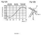
- Fig. 1 illustrates explanatory views of a sensor output when a uniaxial acceleration sensor is arranged horizontally.
- Fig. 1(A) is an explanatory view of an output waveform and
- Fig. 1(B) is an explanatory view of a state of inclining a vehicle body by an angle ⁇ to the right.
- a motor cycle is regarded to be in a turnover state when the vehicle body is inclined to exceed a bank angle (about 65 through 70°) and with 70° as a criterion, turnover can be determined when the criterion is exceeded. Therefore, the sensor output in the case of 70° constituting the criterion becomes as follows when a determining output is designated by notation Vc.
- an error of the angle in the case of constituting an A/D conversion error as ⁇ 10mV ( ⁇ 0.03g) becomes as shown below. (0.94-0.03)g ⁇ g ⁇ sin65° (0.94+0.03)g ⁇ g ⁇ sin75°
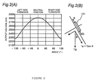
- Fig. 2 illustrates explanatory views of a sensor output when a uniaxial acceleration sensor is arranged vertically.
- Fig. 2(A) is an explanatory view of an output waveform and
- Fig. 2(B) is an explanatory view of a state of inclining a vehicle body by an angle ⁇ to the left.
- the motor cycle is regarded to be in the turnover state when the vehicle body is inclined to exceed the bank angle (about 65 through 70°) and with 70° as the criterion, turnover can be determined when the criterion is exceeded. Therefore, the sensor output in the case of 70° constituting the criterion becomes as follows when the determining output is designated by notation Vc.
- an error of angle in the case of constituting the A/D conversion error by ⁇ 10mV ( ⁇ 0.03g) is as shown below. (0.34-0.03)g ⁇ g ⁇ cos72° (0.34+0.03)g ⁇ g ⁇ cos68° Therefore, the angle error based on A/D conversion becomes 70 ⁇ 2°.
- the angle error based on A/D conversion in the case of vertical arrangement shown in Fig. 2 is smaller than that in the case of horizontal arrangement shown in Fig. 1. Therefore, according to an embodiment, in the case of using a uniaxial acceleration sensor, by vertically arranging (Z direction) the sensor, the A/D conversion error can be reduced and the detection accuracy can be increased.
- one detecting direction is necessarily arranged vertically (Z direction) and a second detecting direction is constituted by a horizontal vehicle width direction (Y direction) or a front and rear direction (X direction).
- the detecting directions of a biaxial acceleration sensor are determined as Z and X directions and the detection output in X direction is changed (when inclination in the front and rear direction is detected), it is also possible to determine that running is steep slope running or willing running and not to regard the change as turnover.
- Fig. 3 is a flowchart of a control example of a turnover detecting apparatus according to an embodiment.
- turnover is determined only by detection by a uniaxial (Z axis direction) sensor.
- Step a1 Output voltage is detected from a turnover sensor vertically arranging a uniaxial acceleration sensor, or a sensor in Z-axis direction which is a first detecting direction of vertical arrangement of a biaxial or triaxial acceleration sensor.
- Step a2 Turnover or not is determined by detecting output voltage of a Z-axis direction sensor. That is, it is determined whether there is constituted a state in which the detecting output voltage is smaller than an output voltage value (g ⁇ cos( ⁇ 70°)) in correspondence with ⁇ 70° constituting a turnover determining reference angle in the above-described cosine curve of Fig. 2(A). When the state continues for 2 seconds or more, turnover is determined. Further, the required condition is constituted by continuation of the state of 2 seconds or more to promote reliability in determining turnover by detecting the voltage.
- Step a3 When turnover is determined, a fuel pump is stopped and fuel injection and ignition are stopped to thereby stop the engine. At this occasion, it is preferable to gradually reduce an engine output. For example, application of a drive pulse signal to an ignition coil in an ignition cycle by normal control, is stopped at a pertinent interval to thereby control ignition by thinning control and the number of times of ignition by normal control is reduced to thereby reduce the output. At this occasion, according to a thinning interval of stopping ignition, ignition is cut firstly at a long interval and ignition is thinned to gradually shorten the interval. Therefore, the vehicle body is prevented from being unstable by rapidly reducing the output in the case of erroneous operation or the like.
- thinning of fuel injection may similarly be carried out.
- application of a drive pulse signal to a solenoid of an injector is gradually reduced to thereby reduce the output.
- the output may be reduced by controlling the electronic throttle.
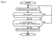
- Fig. 4 is flowchart of other control example of a turnover control apparatus according to a further embodiment.
- a turnover determining condition based on a Y-axis sensor is added.
- Step b1 A biaxial acceleration sensor is vertically arranged and detecting directions are constituted by Z-axis (up and down direction) and Y-axis (left and right direction). Output voltage of the acceleration sensor is detected with respect to Z-axis and Y-axis directions.
- Step b2 Turnover or not is determined by detecting output voltage of the Z-axis direction sensor. That is, it is determined whether there is constituted the state in which the detecting output voltage is smaller than the output voltage value (g ⁇ cos( ⁇ 70°)) in correspondence with ⁇ 70° constituting the turnover determining reference angle in the above-described cosine curve of Fig. 2(A). Turnover is determined when the state continues for 2 seconds or more. Further, as described above, the required condition is constituted by continuation of the state for 2 seconds or more to promote reliability in determining turnover by detecting the voltage.
- Step b3 In the case of determining turnover by the sensor in the Z-axis direction at the above-described step b2, turnover or not is determined further by detecting output voltage of the Y-axis direction sensor. That is, it is determined whether there is constituted a state in which the output voltage is larger than the output voltage value (g ⁇ sin(70°)) or a state in which the detecting output voltage is smaller than g ⁇ sin(-70°)) in correspondence with ⁇ 70° constituting turnover determining reference angles in the above-described sine curve of Fig. 1(A). Turnover is determined when the state continues for 2 seconds or more.
- Step b4 When turnover is determined, the fuel pump is stopped and fuel injection and ignition are stopped to thereby stop the engine. At this occasion, as described above, it is preferable to gradually reduce the engine output.
- Fig. 5 is a block diagram of another embodiment.
- input to CPU for determining turnover is divided into two routes of DC input and AC input.
- Z-axis output from a Z-axis sensor of a biaxial acceleration sensor 2 is inputted to an A/D converter 4 via a noise removing filter 3, subjected to A/D conversion in the A/D converter 4 and inputted to CPU 7 in ECU to determine the turnover state by operation processing.
- the route is DC input route.
- Y-axis output from a Y-axis sensor of the biaxial acceleration sensor 2 is inputted to the A/D converter 4 via a smoothing capacitor 5 and a filter 6, subjected to A/D conversion at the A/D converter 4 and inputted to CPU 7 in ECU to determine the turnover state by operation processing.
- the route is an AC input route.
- the Y-axis sensor is an auxiliary sensor for preventing erroneous operation by determining willing running or the like as mentioned above. Therefore, it is sufficient when the Y-axis sensor determines whether the vehicle body is inclined from a straight state in running. Hence, the input from the Y-axis sensor to CPU determines willing running or the like by an amount of changing the output voltage as the AC input. Thereby, it is not necessary to compare the output voltage with the first reference value and calculate a difference therebetween and therefore, a correction of an offset error in the reference value is dispensed with.
- Fig. 6 is a flowchart showing operation of the above-described turnover detecting apparatus of Fig. 5.
- Step c1 The biaxial acceleration sensor is arranged vertically and detecting directions are constituted by Z-axis (up and down direction) and Y-axis (left and right direction). Output voltage of the acceleration sensor is detected with respect to Z-axis and Y-axis directions.
- Step c2 Turnover or not is determined by detecting output voltage of the Z-axis direction sensor. That is, it is determined whether there is constituted a state in which the detecting output voltage is smaller than the output voltage value (g ⁇ cos( ⁇ 70°)) in correspondence with ⁇ 70° constituting the turnover determining reference angles. When the state continues for 2 seconds or more, turnover is determined. Further, as described above, the required condition is constituted by continuation of the state for 2 seconds or more to promote reliability in determining turnover by detecting the voltage.
- Step c3 When turnover is determined by the sensor in the Z-axis direction at the above-described step c2, turnover or not is determined further by detecting output voltage of the Y-axis direction sensor. In this case, it is determined whether the output voltage of the horizontal Y-axis sensor is changed by a predetermined value (for example, 200mV) in the above-described sine curve of Fig. 1(A) and a difference from the neutral position is not calculated.
- a predetermined value for example, 200mV
- step c2 When there is not a change in inclination in the horizontal direction (vehicle left and right direction) (when the output voltage is equal to or smaller than 200mV), detection of turnover at the above-described step c2 is constituted by inclination of the vehicle body in the front and rear direction by willing running or the like, a turnover processing is not carried out and routine of normal control is repeated.
- Step c4 In the case of determining turnover, the fuel pump is stopped and fuel injection and ignition are stopped to thereby stop the engine. At this occasion, as described above, it is preferable to gradually reduce the engine output.
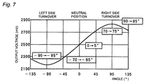
- Fig. 7 is an explanatory diagram of still other embodiment.
- a reduction in detection accuracy by an error in attaching the acceleration sensor is prevented by changing a threshold of detecting voltage of an accelerator sensor.
- an angle of the error in attaching the acceleration sensor is measured and the threshold is changed by an amount of the angle based thereon.
- the attaching error angle in the case of the horizontal sensor, sensor output is measured at three points of -90°, 0°, +90° and the attaching error angle is calculated by an operation processing from a result of the measurement.
- the sensor output is measured at three points of 0°, 90°, 180° and the attaching error angle is calculated by an operational processing from a result of the measurement.
- the threshold of determining turnover is changed based on the inclination angle b calculated in this way.
- the threshold values are changed from ⁇ 70° to -65° and +75°.
- the threshold can be changed in accordance with the left and right direction by determining the left and right inclination direction from the Y-axis sensor.
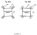
- Fig. 8 illustrates explanatory views of still other embodiment.
- a marking 108, 109 by silk is provided previously at a position for mounting the sensor on the printed board 111 and optical or automatic checking can be facilitated.
- the marking 108, 109 is formed at a position constituting a measure of an allowable range of inclination or an angle of attaching the acceleration sensor 110.
- the shape of the making is not limited to those in Figs. 8(A) and 8(B) but may be any shapes so far as an angle thereof can substantially be identified.
- the error of attaching the acceleration sensor relative to the printed board can be identified, the determination of turnover can be corrected based thereon and a failed product can easily be determined.
- the printed board constituting CPU by mounting the acceleration sensor in this way is contained in a case of ECU.
- Fig. 9 is a flowchart of still other embodiment.
- the detection accuracy is promoted by dealing with a problem in which the detection accuracy is deteriorated by a dispersion in offset, aging change, temperature characteristic or the like of a turnover sensor, which has been problematic conventionally and correcting the turnover sensor by using a speed sensor.
- Step d1 Vehicle speed is detected by a speed sensor and inclination of the vehicle body is detected by a turnover sensor (acceleration sensor).
- Step d2 It is determined whether a state in which a detecting value of the speed sensor exceeds a predetermined value (30km/h according to the example) and an output voltage change of a turnover sensor is less than a predetermined value (10mV according to the example), continues for 10 seconds or more. When the state continues for 10 seconds or more, it is determined that the vehicle body is running in a straight attitude.
- Step d3 When it is determined in the above-described step d3 that the vehicle body is running in the straight attitude, an output of the turnover sensor or an average value thereof is updated and held as a central value (output voltage value at the neutral position of Fig. 1 and Fig. 2).
- Step d4 It is determined whether turnover (inclination is 70° or more) or not is determined by detecting a change from the central value. Thereby, turnover can highly accurately be detected regardless of the temperature characteristic or the dispersion in the offset by the attaching error or the aging change or the like of the sensor.
- Step d5 When turnover is determined, the fuel pump is stopped and fuel injection and ignition are stopped to thereby stop the engine. At this occasion, as described above, it is preferable to gradually reduce the engine output.
- Fig. 10 is a flowchart of still other embodiment.
- the embodiment prevents such an erroneous determination and determines turnover regardless of the Y-axis sensor when inclination of ⁇ 90° or more is detected by the Z-axis sensor.
- Step e1 A biaxial acceleration sensor is vertically arranged and detecting directions are constituted by Z-axis (up and down direction) and Y-axis (left and right direction). Output voltage of the acceleration sensor is detected with regard to Z-axis and Y-axis directions.
- Step e2 Upside-down turnover (turnover of ⁇ 90° or more) or not is determined by detecting output voltage of the Z-axis direction sensor. That is, in the above-described cosine curve of Fig. 2(a), the turn determining angle is set to ⁇ 90° and it is determined whether there is a state in which the detecting output voltage is smaller than an output voltage value (g ⁇ cos( ⁇ 90°)) in correspondence therewith. When the state continues for 2 seconds or more, the upside-down turnover is determined. Further, the required condition is constituted by continuation of the state for 2 seconds or more to promote reliability in determining turnover by detecting the voltage.
- step e4 carries out turnover control of stopping the fuel pump or the like.
- Step e3 When it is determined that the turnover is not the upside-down turnover (not inclined by ⁇ 90° or more) by the sensor in the Z-axis direction at the above-described step e2, the turnover (turnover within ⁇ 90°) or not is determined by detecting output voltages of the Z-axis sensor and the Y-axis sensor.
- the turnover or not is determined by the detecting output voltage of the Z-axis direction sensor. According thereto, as described above, it is determined whether there is constituted a state in which the detecting output voltage is smaller than the output voltage value (g ⁇ cos( ⁇ 70°)) in correspondence with ⁇ 70° constituting the turnover determining reference angles in the cosine curve of Fig. 2(A). When the state continues for 2 seconds or more, turnover is determined. Further, as described above, the required condition is constituted by continuation of the state for 2 seconds or more to promote reliability in determining turnover by detecting the voltage.
- the turnover determining reference angle is set to ⁇ 50°.
- the detection accuracy of the horizontal Y-axis sensor is promoted more than that when the determining angle is set to ⁇ 70° as is known from the above-described graph of Fig. 1.
- the turnover determining reference angle is set to ⁇ 50° and turnover is determined by a state in which the output voltage value of the Y-axis sensor in correspondence therewith is larger than (g ⁇ sin(50°)) or a state in which the output voltage value is smaller than (g ⁇ sin(-50°)).
- turnover is determined.
- the Y-axis sensor detects that the vehicle body is not determined in the left and right direction, this is the state in which the vehicle body is inclined in the front and rear direction by willing running or the like and routine of normal control is repeated.
- Step e4 When turnover is determined, the fuel pump is stopped and fuel injection and ignition are stopped to thereby stop the engine. As described above, it is preferable to gradually reduce the engine output.
- a turnover detecting apparatus of a motor cycle characterized in that in a turnover detecting apparatus of a motor cycle having a turnover sensor for detecting turnover based on an inclination angle of an ECU for controlling to drive an engine and a vehicle body wherein the turnover sensor is constituted by an acceleration sensor, the acceleration sensor is integrated into the ECU, and a direction of detecting an acceleration when the vehicle body is brought into an uninclined state is arranged in a direction vertical to a ground.
- the turnover sensor by constituting the acceleration sensor and integrating the acceleration sensor in ECU to thereby integrally unitize, the detecting accuracy of turnover can be promoted and the constitution can be simplified, by constituting arrangement of the acceleration sensor by vertical arrangement, that is, arrangement in which a direction of detecting acceleration when the vehicle body is brought into the uninclined state, constitutes a direction vertical to the ground, when the vehicle body is turned over by exceeding a bank angle or brought into a turnover state, a change in a detecting output relative to a change in an inclination angle at a vicinity of the bank angle (65 through 70°) constituting an angle of determining the turnover state, is large and therefore, a change in the angle in a constant A/D conversion output width is reduced and therefore, the conversion error can be reduced and reliability can be promoted by increasing accuracy of determining turnover.
- vertical arrangement that is, arrangement in which a direction of detecting acceleration when the vehicle body is brought into the uninclined state, constitutes a direction vertical to the ground, when the vehicle body is turned over by exceeding a
- a preferable constitution example of said turnover detecting apparatus is characterized in that the acceleration sensor constitutes a first detecting direction by the detecting direction vertical to the ground and detects an acceleration in a second detecting direction along with the acceleration in the first detecting direction and in a direction orthogonal to the first detecting direction.
- a biaxial or triaxial acceleration sensor necessarily constituting the vertical detecting direction (first detecting direction) with regard to one axis and detecting the acceleration in the second detecting direction with regard to a vehicle width direction or a front and rear direction, when a turnover angle is exceeded by detecting the angle in the first detecting direction, based on a result of detection in the second detecting direction, inclination of the vehicle body by willing running or slope running can be prevented from being determined erroneously as turnover.
- a further preferable constitution example of said turnover detecting apparatus is characterized in that the acceleration in the first detecting direction is detected based on a difference from a previously set reference value in the uninclined state and the acceleration in the second detecting direction is detected based on an amount of changing the acceleration.
- the inclination angle of the vehicle body is determined based on the difference from the reference value with an offset error of detecting data based on an attaching error or the like corrected with regard to the first detecting direction and it is determined whether there is a change in the inclination with regard to the second detecting direction for determining the inclination other than that of turnover by willing running or the like, turnover or willing running or the like can be identified and therefore, it is not necessary to calculate the difference from the reference value and therefore, it is not necessary to correct the offset error of the reference value.
- a further preferable constitution example of the turnover detecting apparatus is characterized in that a threshold of determining the turnover in the first detecting direction is changed based on an angle of attaching the acceleration sensor.
- the threshold is changed in accordance with the left and right direction by determining the inclination direction in the left and right direction from the output in the second detecting direction.
- Further preferable constitution example of the turnover detecting apparatus is characterized in that when a running speed is equal to or larger than a constant value and the amount of changing a detecting output of the acceleration sensor is equal to or smaller than a constant value, a detected average value of the acceleration sensor is held as data of a central value and the turnover is determined with the central value as the reference value.
- the turnover sensor by constituting the acceleration sensor and assembling the acceleration sensor in ECU to thereby integrally unitize, the detection accuracy of turnover can be promoted and the constitution can be simplified, and also by constituting arrangement of the acceleration sensor by the vertical arrangement, that is, arranging the acceleration detecting direction in the uninclined state of the vehicle body to constitute the direction vertical to the ground, when the vehicle body is turned over by exceeding the bank angle or brought into the turnover state, a change in the detecting output relative to the change in the inclination angle at a vicinity of the bank angle (65 through 70°) constituting the determining angle in the turnover state, is large and therefore, the change in the angle within the constant A/D conversion output width is reduced and therefore, the conversion error can be reduced and reliability can be promoted by promoting the accuracy of determining turnover.
- the acceleration sensor in which the first detecting direction is constituted by the detecting direction vertical to the ground and the accelerations in the first detecting directions as well as the second detecting direction orthogonal thereto are detected, by using the biaxial or triaxial acceleration sensor, necessarily constituting the vertical detecting direction (first detecting direction) with respect to one axis and detecting the acceleration in the second detecting direction with regard to the vehicle width direction or the front and rear direction, when the turnover angle is exceeded by detecting the angle in the first detecting direction, based on the detection result in the second detecting direction, the inclination of the vehicle body by willing running or steep slope running can be prevented from being determined erroneously as turnover.
- the acceleration in the first detecting direction is detected based on the difference from the previously set reference value in an uninclined state and the acceleration in the second detecting direction is detected based on the amount of changing the acceleration
- the inclination angle of the vehicle body is determined based on the difference from the reference value with the offset error of the detection data based on the attaching error or the like corrected with regard to the first detecting direction and it is determined whether there is the change in the inclination with regard to the second detecting direction for determining the inclination other than turnover by willing running or the like, turnover or willing running or the like can be identified and therefore, it is not necessary to calculate the difference from the reference value and therefore, it is not necessary to correct the offset error of the reference value.
- the detection accuracy can be promoted by changing the threshold in determining turnover in correspondence with the inclined angle.
- the detected average value of the acceleration sensor in the case in which the running speed is equal to or larger than the constant value and the amount of changing the detecting output of the acceleration sensor is equal to or smaller than the constant value is held as the central value and turnover is determined with the central value as the reference value
- the running speed is equal to or larger than the constant value and the change in the output of the acceleration sensor is equal to or smaller than the constant value
- the vehicle body is determined to be running in the straight attitude in which the vehicle body is hardly inclined and the average value of the sensor output in this case is held at the central value.
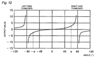
- Fig. 11 is a flowchart of still other embodiment of the invention. Further, Fig. 12 is a graph of output data of tan (tangent) used in the embodiment.
- Step f1 A biaxial acceleration sensor is vertically arranged and detecting directions are constituted by Z-axis (up and down direction) and Y-axis (left and right direction). Output voltage of the acceleration sensor is detected with respect to Z-axis and Y-axis directions.
- Step f2 Upside-down turnover (turnover of ⁇ 90° or more) is determined by detecting output voltage of a Z-axis direction sensor. That is, in the above-described cosine curve of Fig. 2(A), a turnover determining angle is set to ⁇ 90° and it is determined whether there is constituted a state in which the detecting output voltage is smaller than an output voltage value (g ⁇ cos( ⁇ 90°)) in correspondence therewith. When the state continues for 2 seconds or more, upside-down turnover is determined. Further, as described above, the required condition is constituted by continuation of the state for 2 seconds or more to promote reliability in determining turnover by detecting the voltage.
- step f4 When upside-down turnover is determined at this occasion, the operation immediately proceeds to step f4 and carries out turnover control of stopping the fuel pump or the like.
- Step f3 When it is determined that upside-down turnover is not constituted (no inclined by ⁇ 90° or more) by the Z-axis direction sensor at the above-described step f2, turnover (turnover within ⁇ 90°) or not is determined further by the detecting output voltages of the Z-axis sensor and a Y-axis direction sensor.
- a turnover angle is designated by notation ⁇
- turnover is determined.
- the required condition is constituted by continuation of the state for 2 seconds or more to promote reliability in determining turnover by the tangent output value.
- Fig. 12 shows a tangent curve output provided by the sine curve output from the horizontal Y-axis sensor of Fig. 1(A) and the cosine curve output from the vertical Z-axis sensor of Fig. 2(A).
- the vehicle body angle falls in a range of from -90° to +90° because it is not determined as upside-down turnover in the above-described step f2. It is determined whether the turnover angle ⁇ is exceeded on the left side (-side) or the right side (+side) of the vehicle body in the range.
- the turnover angle ⁇ is set in consideration of a vehicle kind of a scooter type or a normal autobicycle type, a vehicle dimension or a displacement or the like.
- the ⁇ may be made rewritable on a program in accordance with the vehicle kind or the like.
- Step f4 When turnover is determined, the fuel pump is stopped and fuel injection and ignition are stopped to thereby stop the engine. At this occasion, as described above, it is preferable to gradually reduce the engine output.
- a turnover detecting apparatus of a motor cycle characterized in that in a turnover detecting apparatus of a motor cycle having a turnover sensor for detecting turnover based on an inclination angle of an ECU for controlling to drive an engine and a vehicle body wherein the turnover sensor is constituted by an acceleration sensor, the acceleration sensor is integrated into the ECU, and a direction of detecting an acceleration when the vehicle body is brought into an uninclined state is arranged in a direction vertical to a ground.
- the turnover sensor by constituting the acceleration sensor and integrating the acceleration sensor in ECU to thereby integrally unitize, the detecting accuracy of turnover can be promoted and the constitution can be simplified, by constituting arrangement of the acceleration sensor by vertical arrangement, that is, arrangement in which a direction of detecting acceleration when the vehicle body is brought into the uninclined state, constitutes a direction vertical to the ground, when the vehicle body is turned over by exceeding a bank angle or brought into a turnover state, a change in a detecting output relative to a change in an inclination angle at a vicinity of the bank angle (65 through 70°) constituting an angle of determining the turnover state, is large and therefore, a change in the angle in a constant A/D conversion output width is reduced and therefore, the conversion error can be reduced and reliability can be promoted by increasing accuracy of determining turnover.
- vertical arrangement that is, arrangement in which a direction of detecting acceleration when the vehicle body is brought into the uninclined state, constitutes a direction vertical to the ground, when the vehicle body is turned over by exceeding a
- a preferable constitution example is characterized in that the acceleration sensor constitutes a first detecting direction by the detecting direction vertical to the ground and detects an acceleration in a second detecting direction along with the acceleration in the first detecting direction and in a direction orthogonal to the first detecting direction.
- a biaxial or triaxial acceleration sensor necessarily constituting the vertical detecting direction (first detecting direction) with regard to one axis and detecting the acceleration in the second detecting direction with regard to a vehicle width direction or a front and rear direction, when a turnover angle is exceeded by detecting the angle in the first detecting direction, based on a result of detection in the second detecting direction, inclination of the vehicle body by willing running or slope running can be prevented from being determined erroneously as turnover.
- a further preferable constitution example is characterized in that the acceleration in the first detecting direction is detected based on a difference from a previously set reference value in the uninclined state and the acceleration in the second detecting direction is detected based on an amount of changing the acceleration.
- the inclination angle of the vehicle body is determined based on the difference from the reference value with an offset error of detecting data based on an attaching error or the like corrected with regard to the first detecting direction and it is determined whether there is a change in the inclination with regard to the second detecting direction for determining the inclination other than that of turnover by willing running or the like, turnover or willing running or the like can be identified and therefore, it is not necessary to calculate the difference from the reference value and therefore, it is not necessary to correct the offset error of the reference value.
- a further preferable constitution example is characterized in that a threshold of determining the turnover in the first detecting direction is changed based on an angle of attaching the acceleration sensor.
- the threshold is changed in accordance with the left and right direction by determining the inclination direction in the left and right direction from the output in the second detecting direction.
- Further preferable constitution example is characterized in that when a running speed is equal to or larger than a constant value and the amount of changing a detecting output of the acceleration sensor is equal to or smaller than a constant value, a detected average value of the acceleration sensor is held as data of a central value and the turnover is determined with the central value as the reference value.
- a further preferable constitution example is characterized in further comprising a sensor in a vertical direction and a sensor in a horizontal direction, wherein the turnover is determined based on (horizontal sensor output) ⁇ (vertical sensor output).
- turnover can be detected highly reliably with no erroneous determination in a short period of time without using a noise removing filter or the like even when an output value of detecting turnover is varied by vibration of the vehicle body or the like.
- the acceleration sensor when used as a turnover sensor for a motor cycle, there is a case in which an angle of detecting turnover constituting a threshold of determining turnover is changed by vibration of the vehicle body or the like.
- the angle of detecting turnover can be maintained constant by removing a vibration component by providing a filter in a control circuit.
- the filter when the filter is provided, there is brought about a concern that a long response time period is taken, a detecting time period is prolonged and the turnover is dealt with retardedly.
- a turnover sensor capable of detecting turnover with no erroneous determination by eliminating a variation in the turnover detecting angle caused by vibration of a vehicle body or the like without prolonging a detection time period. Such a request is also met by the embodiment.
- the turnover sensor by constituting the acceleration sensor and assembling the acceleration sensor in ECU to thereby integrally unitize, the detection accuracy of turnover can be promoted and the constitution can be simplified, and also by constituting arrangement of the acceleration sensor by the vertical arrangement, that is, arranging the acceleration detecting direction in the uninclined state of the vehicle body to constitute the direction vertical to the ground, when the vehicle body is turned over by exceeding the bank angle or brought into the turnover state, a change in the detecting output relative to the change in the inclination angle at a vicinity of the bank angle (65 through 70°) constituting the determining angle in the turnover state, is large and therefore, the change in the angle within the constant A/D conversion output width is reduced and therefore, the conversion error can be reduced and reliability can be promoted by promoting the accuracy of determining turnover.
- the acceleration sensor in which the first detecting direction is constituted by the detecting direction vertical to the ground and the accelerations in the first detecting directions as well as the second detecting direction orthogonal thereto are detected, by using the biaxial or triaxial acceleration sensor, necessarily constituting the vertical detecting direction (first detecting direction) with respect to one axis and detecting the acceleration in the second detecting direction with regard to the vehicle width direction or the front and rear direction, when the turnover angle is exceeded by detecting the angle in the first detecting direction, based on the detection result in the second detecting direction, the inclination of the vehicle body by willing running or steep slope running can be prevented from being determined erroneously as turnover.
- the acceleration in the first detecting direction is detected based on the difference from the previously set reference value in an uninclined state and the acceleration in the second detecting direction is detected based on the amount of changing the acceleration
- the inclination angle of the vehicle body is determined based on the difference from the reference value with the offset error of the detection data based on the attaching error or the like corrected with regard to the first detecting direction and it is determined whether there is the change in the inclination with regard to the second detecting direction for determining the inclination other than turnover by willing running or the like, turnover or willing running or the like can be identified and therefore, it is not necessary to calculate the difference from the reference value and therefore, it is not necessary to correct the offset error of the reference value.
- the detection accuracy can be promoted by changing the threshold in determining turnover in correspondence with the inclined angle.
- the detected average value of the acceleration sensor in the case in which the running speed is equal to or larger than the constant value and the amount of changing the detecting output of the acceleration sensor is equal to or smaller than the constant value is held as the central value and turnover is determined with the central value as the reference value
- the running speed is equal to or larger than the constant value and the change in the output of the acceleration sensor is equal to or smaller than the constant value
- the vehicle body is determined to be running in the straight attitude in which the vehicle body is hardly inclined and the average value of the sensor output in this case is held at the central value.
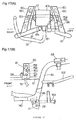
- Fig. 13 is an outlook view of a small-sized motor cycle to which the invention is applied.
- a vehicle body 1 has a handlebar 2 at its front portion, and the handlebar 2 is connected to a front wheel 5 via a steering shaft 4 through which a head pipe 3 is passed.
- a vehicle body frame 6 is joined to the head pipe 3.
- the vehicle body frame 6 forms a frame structure of the whole vehicle body.
- the front portion of the vehicle body is covered with a cowling 7.
- the vehicle body 1 is covered with a vehicle body cover 8 from the outside.
- a seat 9 is provided in the center of the vehicle body 1, a fuel tank 10 is provided under the seat 9 and a helmet box (container) 11 is provided in the back of the seat 9.
- the fuel tank 10 supplies fuel to an injector (not shown) via a fuel hose (not shown).
- a breather hose 12 is connected to the top of the fuel tank 10 and the other end is connected to a canister 13.
- the canister 13 is connected to an intake system (for example, throttle body) via a purge hose 14.
- a throttle wire 15 is fixed to a throttle grip (or lever) on a right side handlebar part (not shown) and is connected to the throttle valve of the intake system.
- a brake cable 16 is fixed to a brake lever (not shown) on the handlebar part and is connected to a brake camshaft 18 of a rear wheel 17.
- An engine unit 19 is installed on the vehicle body frame 6 in the center of the vehicle body 1.
- the engine unit 19 includes an engine (not shown) and a speed reduction unit 24 integrally combined with its crankcase (not shown).
- This engine unit 19 is hung on a bottom vehicle body frame member 21 constituting a part of the vehicle body frame 6 via an engine bracket 20 so that it can turn around a pivot 22.
- a rear wheel 17 is connected to the rear portion of the engine unit 19 and the bottom end of a damper 23 is connected thereto so as to be able to turn.
- the top end of the damper 23 is connected to a rear vehicle body frame (not shown) constituting a part of the vehicle body frame 6 so as to be able to turn. This enables the engine unit 19 to swing around the pivot 22 with the rear wheel 17. In this manner, a swing unit type engine is formed.
- An air cleaner 25 is mounted on the top side of the speed reduction unit 24.
- An outside air intake opening 25a is made in the front portion of the air cleaner 25 and a dust prevention cover 26 made of rubber or resin is provided inside the vehicle body cover 8 so as to cover the opening.
- a reference numeral 27 denotes a stand and 28 denotes a kick lever.
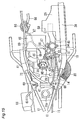
- Fig. 14 and Fig. 15 are a side view and a plan view to show a main portion of the motorcycle having a fuel injection engine in accordance with the invention, respectively.
- Fig. 16 is an enlarged view of its intake system portion.
- An engine 29 is provided under the fuel tank 10.
- the engine 29 is a four-cycle single cylinder engine having a fuel injector.
- the crankcase (not shown) of the engine 29 is integrally combined with the speed reduction unit 24 constructed of a V-belt type continuously variable speed reduction mechanism, for example, to constitute the engine unit 19 of the swing unit engine type as a whole.
- a duct 30 is connected to the front portion of the speed reduction unit 24 and the outside air is sucked from its opening end 30a and is supplied into the speed reduction unit 5 to cool its inside.
- a rear output shaft (not shown) of the speed reduction unit 24 is connected to the axle of the rear wheel 17.
- the engine bracket 20 is integrally combined with the front portion of the engine unit 19 of the swing unit engine type.
- a link plate 32 is rotatably mounted on the engine bracket 20 via a shaft 31.
- the link plate 32 is mounted on the bottom vehicle frame member 21 via the pivot 22 so as to turn.
- the damper (shock absorber) 23 is provided on the rear portion of the engine unit 19.
- the top end 33 of the damper 23 is rotatably mounted on a rear vehicle body frame member 34 and the bottom end 35 thereof is rotatably mounted on a bracket 36 on the rear end portion of the engine unit 19.
- the engine unit 19 is mounted on the vehicle body frame in such a way as to be able to swing around the pivot 22 on its front side.
- the cylinder 37 of the engine 29 is inclined forward nearly to a horizontal level.
- a crankshaft 38 swings with the shaft 31 of the engine bracket 20 (Fig. 14) around the above-mentioned pivot 22 in the manner shown by an arrow D.
- an intake manifold 39 communicating with an intake port (not shown) of a cylinder head and an intake pipe 40 (Fig. 15, Fig. 16) connected to the intake manifold 39, whereas to its exhaust side is connected an exhaust pipe 41 (Fig. 15).
- the intake pipe 40 is the intake pipe bent and shaped like an elbow and, as shown in Fig. 16, is fixed to the intake manifold 39 by means of two bolts 44 with its flange 43 made to abut on that of the intake manifold 39 via a heat insulating member 42 made of resin.
- a reference numeral 45 is a maintenance cover of a valve train cam.
- the engine 29 is mounted with a water temperature sensor 46 (Fig. 15, Fig. 16).
- the detection output signal of the water temperature sensor 46 is sent to an engine control unit 47 (Fig. 15) via a water temperature signal cable 89 (Fig. 15) and a wire harness 72.
- an engine control unit 47 Fig. 15
- a water temperature signal cable 89 Fig. 15
- a wire harness 72 To the engine control unit 47 via the wire harness 72 are further connected detection signal cables (not shown) of an intake air temperature and an intake pressure sensor, both of which will be described below.
- a throttle valve (not shown) is opened or closed based on these detection data.
- a throttle body 48 is connected to the intake manifold 39 via the above-mentioned intake pipe 40 that is bent and shaped like an elbow.
- the throttle body 48 is connected to the air cleaner 25 via a joint 49.
- On the intake pipe 40 is mounted an injector 50.
- the throttle valve (not shown) and on its upstream side is mounted a suction piston 51 of a diaphragm type.
- a suction piston 51 of a diaphragm type.
- its diaphragm chamber 52 is made in the top side of the throttle body 48 and an air intake port 54 (open to outside air) of an air passage 53 for introducing air into the diaphragm chamber 52 is made in the bottom side in the throttle body 48.
- the throttle wire 15 connected to the throttle lever or the throttle grip (both not shown) is connected to the valve shaft of the throttle valve via a link 55.
- the air intake opening 25a in the front portion of the air cleaner 25 is covered with the dust prevention cover 26 (shown by a single dot and dash line in Fig. 13) made of rubber or resin.
- Another vehicle body cover is further mounted on the outside of the dust prevention cover 26.
- the air intake port 54 of the suction piston 51 is made inside the dust prevention cover 26.
- An automatic choke 56 of a heater wax type and an intake pressure sensor 57 are provided next to the suction piston 51 on the throttle body 48 (Fig. 15).
- the automatic choke 56 opens or closes a bypass pipe (not shown) for making the upstream side of the throttle valve communicating with the downstream side thereof.
- the intake pressure sensor 57 communicates with the intake manifold 39 or the intake pipe 40 via a negative pressure hose 58 (Fig. 16).
- An intake air temperature sensor 59 (Fig. 15) is provided in the air cleaner 25.
- the intake pressure sensor 57 may be provided near the intake manifold. Moreover, a throttle position sensor (not shown) may be provided on the valve shaft of the throttle valve opposite to the link 55. In this case, the automatic choke 56 is provided on the upstream side of the throttle valve so that it does not interfere with the throttle position sensor.
- the front side bottom portion of the fuel tank 10 is fixed to left and right vehicle body frames 61 via brackets 60.
- a fuel hose 62 is pulled out of the rear side of the fuel tank 10 to supply the injector 50 with fuel.
- the fuel hose 62 is fixed to the rear vehicle body frame member 34 via a stay 63 (Fig. 14, Fig. 16).
- a reference numeral 64 (Fig. 14) denotes an overflow pipe
- 65 (Fig. 15) denotes a battery
- 66 (Fig. 15) denotes a recovery tank of coolant.
- This secondary air introduction system 86 communicates with the intake manifold via a negative pressure hose 87 and supplies outside air to a catalyst (not shown) via an air hose 88 in response to an intake negative pressure to burn the exhaust gas again.
- blowby gas hose 90 To the air cleaner 25, as shown in Fig. 14, is connected a blowby gas hose 90.
- This blowby gas hose 90 communicates with a cam chain chamber (not shown) communicating with the crankcase (not shown) of the engine 29 and prevents an oil seal from being dropped or a power from being lost by a pressure rise in the crankcase of the engine.
- the blowby gas hose 90 is connected to a clean side after passing of an element in the air cleanser and the blowby gas is again introduced into a combustion chamber.
- a rollover valve 124 At the middle of the breather hose 12 is provided a rollover valve 124. This rollover valve 124 is closed when the vehicle is turned over to prevent the fuel from flowing from the fuel tank 10.
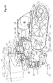
- Figs. 17(A), 17(B) are a front side view and a left side view of a portion where the engine control unit is installed.
- the engine control unit (ECU) 47 in this arrangement example, is substantially rectangular shape in which a bottom part 47b protruding to the front side is larger in thickness than a top part 47a to form a stepped shape, has a rectangular mounting plane 47c on the rear side, and has ear parts 158 extending to the left and right sides on the same plane of the mounting plane 47c.
- Each of the ear parts 158 is fixed to a stay 160 welded to the inside of the bracket 60 for supporting the fuel tank by a bolt 159.
- the wire harness 72 is connected to the bottom of the ECU 47 via a coupler 161.
- the bracket 60 is joined to the vehicle body frame member 61 joined to each of the left and right rear vehicle body frame members 34.
- Each of the left and right rear vehicle body frame members 34 is joined to a front vehicle body frame member 140 via an elbow frame 145.
- To the elbow frame 145 is joined the above-mentioned bottom vehicle frame member 21 described above and on the bottom vehicle frame member 21 is mounted the pivot 22 for supporting the above-mentioned engine unit 19 (Fig. 13, Fig. 14) so that the above-mentioned engine 19 can swing.
- a reference numeral 162 denotes a footrest pipe frame for a tandem rider and 163 denotes a side stand.
- the fuel tank (not shown) is supported by a support part (not shown) provided across the top portions of the left and right brackets 60 and the stay 63 provided on the top of the rear vehicle body frame 34.
- a circuit board (not shown) arranged in parallel to the mounting plane 47c and a two-dimensional (biaxial) acceleration sensor (not shown) is mounted on the circuit board with its detection surface in parallel to the surface of the circuit board. Therefore, the turnover sensor (which could also be utilized as a rollover sensor) including the two-dimensional acceleration sensor is mounted with its detection surface nearly vertical to the front and rear direction of the vehicle body at a position protected by the left and right brackets 60 nearly in the center in the left and right direction of the vehicle body.
- Figs. 18(A), 18(B) are a rear side front view and a left side view of a structure for installing an ECU in accordance with another embodiment, respectively.
- a reference numeral 169 denotes an electromagnetic pump for supplying fuel and 170 denotes a filter provided in the middle of a fuel hose (not shown) between the electromagnetic pump 169 and the fuel tank (not shown).
- the ECU 47 is mounted in a state where its mounting plane 47c parallel to the detection surface of the turnover sensor (rollover sensor) including the two-dimensional acceleration sensor provided therein is nearly vertical to the front and rear direction of the vehicle body at a position protected by the left and right pipe frames 165, 166 nearly in the center in the left and right direction of the vehicle body.
- a structure for installing an engine control unit for a motorcycle having a rollover sensor (a turnover sensor), characterized in that the above-mentioned rollover sensor includes a two-dimensional acceleration sensor and is received in the engine control unit and that the engine control unit is installed on a vehicle frame in such a way that the detection surface of the rollover sensor is nearly vertical to a front and rear direction of a vehicle body.
- the two-dimensional acceleration sensor is used as the rollover sensor (turnover sensor) and its two-dimensional detection surface is arranged nearly vertical to the front and rear direction of the vehicle body, so a state of rollover can be surely detected in which the vehicle body is inclined in the left and right direction and is rolled over, and further the engine control unit for receiving the rollover sensor can be mounted in a state slightly inclined in the front and rear direction, so the parts can be easily arranged.
- the rollover sensor is integrally combined with the engine control unit (ECU), the constitution of the parts can be made simple and thus the parts can be arranged efficiently in a narrow space without limiting the arrangement of the other parts.
- a preferable example of constitution is characterized in that the above-mentioned engine control unit is mounted in the center in a left and right direction of the vehicle body.
- this constitution it is possible to detect a vehicle being inclined or rolled over either in the left direction or in the right direction with high accuracy and thus to improve reliability in the detection of rollover, and the engine control unit can be protected by the vehicle body frames on both sides and thus can be prevented being damaged when the vehicle is rolled over or inclined.
- Brackets for mounting a fuel tank are fixed to vehicle body frame members arranged on left and right sides in the center of the vehicle body, and that the engine control unit is arranged between these left and right brackets, and that the engine control unit is fixed to the respective brackets via stays.
- the ECU can be arranged efficiently in a space between the left and right brackets for mounting a fuel tank in the center of the vehicle body and thus the distances from the ECU to various kinds of sensors around an engine such as a water temperature sensor and an intake air temperature sensor and engine driving components such as an injector, a throttle valve, and an ignition coil can be made shorter to shorten a wire harness made of signal cables and the like to thereby simplify a layout around the engine.
- an engine such as a water temperature sensor and an intake air temperature sensor and engine driving components such as an injector, a throttle valve, and an ignition coil can be made shorter to shorten a wire harness made of signal cables and the like to thereby simplify a layout around the engine.
- said two-dimensional acceleration sensor is used as the rollover sensor (turnover sensor) and its two-dimensional detection surface is arranged nearly vertical to the front and rear direction of the vehicle body, so a state of rollover can be surely detected where the vehicle body is inclined and rolled over in the left and right direction, and further the engine control unit for receiving the rollover sensor can be mounted in a state slightly inclined in the front and rear direction, so the parts can be easily arranged.
- the rollover sensor is integrally combined with the engine control unit (ECU), the constitution of these parts can be made simple and thus these parts can be arranged efficiently in a narrow space without limiting the arrangement of the other parts.
- the engine control unit is provided in the center in the left and right direction of the vehicle body, it is possible to detect the vehicle being inclined or rolled over either in the left direction or in the right direction with high accuracy and thus to improve reliability in the detection of rollover, and the engine control unit is mechanically protected by the vehicle body frames on both sides and thus is prevented from being damaged when the vehicle is rolled over.
- the rollover sensor includes a two-dimensional acceleration sensor and is received in an engine control unit 47 and the engine control unit is mounted on a vehicle body frame so that the detection surface of the rollover sensor is nearly vertical to the front and rear direction of the vehicle body.
- the above-mentioned engine control unit 47 is mounted in the center in the left and right direction of the vehicle body.
- a turnover detecting apparatus of a motor cycle including a turnover sensor for detecting turnover based on an inclination angle of an ECU for controlling to drive an engine and a vehicle body, constituting the turnover sensor by an acceleration sensor and integrating the acceleration sensor at inside of the ECU, wherein the acceleration sensor is arranged with a direction of detecting an acceleration when the vehicle body is brought into an uninclined state in a direction vertical to a ground to constitute a first detecting direction and an acceleration in a second detecting direction along with the first detecting direction and in a direction orthogonal thereto is detected.
- the turnover sensor by constituting the turnover sensor by the acceleration sensor and integrating the acceleration sensor to inside of ECU to thereby integrally unitize, promotion of turnover detection accuracy and simplification of the constitution are achieved and the turnover sensor can be laid out efficiently in a narrow space without restricting arrangement of other parts.
- the acceleration sensor in vertical arrangement, that is, arrangement by which the direction of detecting the acceleration when the vehicle body is brought into the uninclined state, becomes a direction orthogonal to the ground, when a bank angle is exceeded and the vehicle body is turned over or brought into a turned over state, a change in a detected output relative to a change in the inclination angle at a vicinity of a bank angle (65 through 70°) constituting an angle of determining the turned over state, is large and therefore, the change in the angle within a constant A/D conversion output width becomes small and therefore, a conversion error can be reduced, accuracy of determining turnover can be promoted and reliability can be promoted.
- a biaxial or triaxial acceleration sensor necessarily constituting the vertical detecting direction (first detecting direction) with regard to one axis and detecting the acceleration in the second detecting direction with regard to a vehicle width direction or a front and rear direction, when a turnover angle is exceeded by detecting the angle in the first detecting direction, based on a result of detection in the second detecting direction, inclination of the vehicle body by willing running or slope running can be prevented from being determined erroneously as turnover.
- a preferable constitution example is characterized in that the acceleration in the first detecting direction is detected based on a difference from a previously set reference value in the uninclined state and the acceleration in the second detecting direction is detected based on an amount of changing the acceleration.
- the inclination angle of the vehicle body is determined based on the difference from the reference value with an offset error of detecting data based on an attaching error or the like corrected with regard to the first detecting direction and it is determined whether there is a change in the inclination with regard to the second detecting direction for determining the inclination other than that of turnover by willing running or the like, turnover or willing running or the like can be identified and therefore, it is not necessary to calculate the difference from the reference value and therefore, it is not necessary to correct the offset error of the reference value.
- a further preferable constitution example is characterized in that a threshold of determining the turnover in the first detecting direction is changed based on an angle of attaching the acceleration sensor.
- the threshold is changed in accordance with the left and right direction by determining the inclination direction in the left and right direction from the output in the second detecting direction.
- Further preferable constitution example is characterized in that when a running speed is equal to or larger than a constant value and the amount of changing a detecting output of the acceleration sensor is equal to or smaller than a constant value, a detected average value of the acceleration sensor is held as data of a central value and the turnover is determined with the central value as the reference value.
- a further preferable constitution example is characterized in further comprising a sensor in a vertical direction and a sensor in a horizontal direction, wherein the turnover is determined based on (horizontal sensor output) ⁇ (vertical sensor output).
- turnover can be detected highly reliably with no erroneous determination in a short period of time without using a noise removing filter or the like even when an output value of detecting turnover is varied by vibration of the vehicle body or the like.
- the acceleration sensor when used as a turnover sensor for a motor cycle, there is a case in which an angle of detecting turnover constituting a threshold of determining turnover is changed by vibration of the vehicle body or the like.
- the angle of detecting turnover can be maintained constant by removing a vibration component by providing a filter in a control circuit.
- the filter when the filter is provided, there arises a concern that a long response time period is taken, a detecting time period is prolonged and the turnover is dealt with retardedly.
- a turnover sensor capable of detecting turnover with no erroneous determination by eliminating a variation in the turnover detecting angle caused by vibration of a vehicle body or the like without prolonging a detection time period. Such a request is also met by the embodiment.
- a further preferable constitution example is characterized in that the turnover sensor comprises a two-dimensional acceleration sensor, the turnover sensor is contained at inside of the ECU and the ECU is attached to a vehicle body frame such that a detecting face of the turnover sensor becomes substantially vertical to a front and rear direction of the vehicle body.
- the two-dimensional (biaxial) acceleration sensor is used as the turnover sensor integrated to inside of ECU, the two-dimensional detecting face is arranged substantially orthogonally to the front and rear direction of the vehicle body, the ECU is attached to the vehicle body frame and therefore, the turnover sensor is firmly fixed to and held by the vehicle body and reliability of attachment and detection is promoted. Further, a degree of freedom of attachment can be promoted and arrangement of parts can be facilitated by attaching ECU containing the turnover sensor to the vehicle body frame with a slight inclination in the front and rear direction in correspondence with a space of arranging surrounding parts or the like.
- a further preferable constitution example is characterized in that the ECU is provided at a central portion in a left and right direction of the vehicle body.
- this constitution it is possible to detect a vehicle being inclined or turned over either in the left direction or in the right direction with high accuracy and thus to improve reliability in the detection of turnover, and the engine control unit can be protected by the vehicle body frames on both sides and thus can be prevented being damaged when the vehicle is turned over.
- Brackets for mounting a fuel tank are fixed to vehicle body frame members arranged on left and right sides in the center of the vehicle body, and that the ECU is arranged between these left and right brackets, and that the ECU is fixed to the respective brackets via stays.
- the ECU can be arranged efficiently in a space between the left and right brackets for mounting a fuel tank in the center of the vehicle body and thus the distances from the ECU to various kinds of sensors around an engine such as a water temperature sensor and an intake air temperature sensor and engine driving components such as an injector, a throttle valve, and an ignition coil can be made shorter to shorten a wire harness made of signal cables and the like to thereby simplify a layout around the engine.
- an engine such as a water temperature sensor and an intake air temperature sensor and engine driving components such as an injector, a throttle valve, and an ignition coil can be made shorter to shorten a wire harness made of signal cables and the like to thereby simplify a layout around the engine.
- the turnover sensor by constituting the turnover sensor by the acceleration sensor and integrating the turnover sensor to inside of ECU to thereby integrally unitize, promotion of turnover detection accuracy and simplification of the constitution are achieved and the turnover sensor can be laid out efficiently in a narrow space without restricting arrangement of other parts.
- the acceleration sensor in vertical arrangement, that is, arrangement by which the direction of detecting the acceleration when the vehicle body is brought into the uninclined state, is in the direction vertical to the ground, when the vehicle body is turned over by exceeding the bank angle or brought into the turndown state, the change in the detected output relative to the change in the inclination angle at a vicinity of the bank angle (65 through 70°) constituting the back angle of determining the turned over state, is large and therefore, the change in the angle within the constant A/D conversion output width is reduced and accordingly, the conversion error can be reduced, the accuracy of determining turndown can be promoted and reliability can be promoted.
- the biaxial or the triaxial acceleration sensor necessarily constituting the direction in vertical arrangement (first detecting direction) with regard to one axis and detecting the acceleration in the second detecting direction with regard to the vehicle width direction or the front and rear direction, when the turnover angle is exceeded by detecting the angle in the first detecting direction, based on a detection result in the second detecting direction, the inclination of the vehicle body by willing running or slope running can be prevented from being determined erroneously as turnover.
- the acceleration in the first detecting direction is detected based on the difference from the previously set reference value in an uninclined state and the acceleration in the second detecting direction is detected based on the amount of changing the acceleration
- the inclination angle of the vehicle body is determined based on the difference from the reference value with the offset error of the detection data based on the attaching error or the like corrected with regard to the first detecting direction and it is determined whether there is the change in the inclination with regard to the second detecting direction for determining the inclination other than turnover by willing running or the like, turnover or willing running or the like can be identified and therefore, it is not necessary to calculate the difference from the reference value and therefore, it is not necessary to correct the offset error of the reference value.
- the detection accuracy can be promoted by changing the threshold in determining turnover in correspondence with the inclined angle.
- the detected average value of the acceleration sensor in the case in which the running speed is equal to or larger than the constant value and the amount of changing the detecting output of the acceleration sensor is equal to or smaller than the constant value is held as the central value and turnover is determined with the central value as the reference value
- the running speed is equal to or larger than the constant value and the change in the output of the acceleration sensor is equal to or smaller than the constant value
- the vehicle body is determined to be running in the straight attitude in which the vehicle body is hardly inclined and the average value of the sensor output in this case is held at the central value.
- the turnover sensor comprises the two dimensional acceleration sensor
- the turnover sensor is contained at inside of the ECU and the ECU is attached to the vehicle body frame such that the detecting face of the turnover sensor becomes substantially orthogonal to the front and rear direction of the vehicle body
- the two-dimensional (biaxial) acceleration sensor is used as the turnover sensor integrated to inside of ECU
- the two-dimensional detecting face is arranged substantially orthogonally to the front and rear direction of the vehicle body
- the ECU is attached to the vehicle body frame and therefore, the turnover sensor is firmly fixed to and held by the vehicle body and reliability of attachment and detection is promoted.
- the degree of freedom of attachment can be promoted and arrangement of parts can be facilitated by attaching ECU containing the turnover sensor to the vehicle body frame with a slight inclination in the front and rear direction in correspondence with a space of arranging surrounding parts.
- ECU can be arranged spatially efficiently between the brackets by utilizing the left and right brackets for attaching the fuel tank, distances to various sensors of a water temperature sensor, an intake temperature sensor and the like and engine drive parts of an injector, a throttle valve, an ignition coil and the like around the engine are shortened, a wire harness comprising a signal cable or the like can be shortened and layout around the engine is simplified.
- a turnover detecting apparatus of a motor cycle reducing an A/D conversion error of a turnover sensor comprising an acceleration sensor and promoting accuracy of determining turnover
Landscapes
- Engineering & Computer Science (AREA)
- Mechanical Engineering (AREA)
- Chemical & Material Sciences (AREA)
- Combustion & Propulsion (AREA)
- General Engineering & Computer Science (AREA)
- Physics & Mathematics (AREA)
- General Physics & Mathematics (AREA)
- Radar, Positioning & Navigation (AREA)
- Remote Sensing (AREA)
- Combined Controls Of Internal Combustion Engines (AREA)
- Output Control And Ontrol Of Special Type Engine (AREA)
Applications Claiming Priority (8)
| Application Number | Priority Date | Filing Date | Title |
|---|---|---|---|
| JP2001321497 | 2001-10-19 | ||
| JP2001321497 | 2001-10-19 | ||
| JP2001330158 | 2001-10-29 | ||
| JP2001330158 | 2001-10-29 | ||
| JP2002204267 | 2002-07-12 | ||
| JP2002204267 | 2002-07-12 | ||
| JP2002273003A JP4290950B2 (ja) | 2001-10-19 | 2002-09-19 | 自動二輪車の転倒検出装置 |
| JP2002273003 | 2002-09-19 |
Publications (3)
| Publication Number | Publication Date |
|---|---|
| EP1304544A2 true EP1304544A2 (de) | 2003-04-23 |
| EP1304544A3 EP1304544A3 (de) | 2005-07-20 |
| EP1304544B1 EP1304544B1 (de) | 2008-12-17 |
Family
ID=27482632
Family Applications (1)
| Application Number | Title | Priority Date | Filing Date |
|---|---|---|---|
| EP02023603A Expired - Lifetime EP1304544B1 (de) | 2001-10-19 | 2002-10-17 | Zweirad |
Country Status (6)
| Country | Link |
|---|---|
| US (1) | US6941206B2 (de) |
| EP (1) | EP1304544B1 (de) |
| CN (1) | CN1227119C (de) |
| DE (1) | DE60230376D1 (de) |
| ES (1) | ES2317974T3 (de) |
| TW (1) | TW561262B (de) |
Cited By (7)
| Publication number | Priority date | Publication date | Assignee | Title |
|---|---|---|---|---|
| EP1619066A1 (de) * | 2004-07-21 | 2006-01-25 | HONDA MOTOR CO., Ltd. | Kontrolleinheit für einen Verbrennungsmotor mit Neigungssensor |
| EP1873050A1 (de) * | 2006-06-27 | 2008-01-02 | HONDA MOTOR CO., Ltd. | Scooterähnliches Motorrad |
| GB2459719A (en) * | 2008-07-11 | 2009-11-04 | Eddy Alick Bryan | Throttle response inhibitor device for a hand-throttle controlled machine, eg motor cycle |
| WO2011072942A1 (de) * | 2009-12-16 | 2011-06-23 | Robert Bosch Gmbh | Elektrisches zweirad |
| EP3364017A3 (de) * | 2017-02-20 | 2018-10-24 | Yamaha Hatsudoki Kabushiki Kaisha | Grätschsitzfahrzeug |
| US10364766B2 (en) | 2015-02-11 | 2019-07-30 | Continental Automotive France | Method for detecting an inclination of a wheel relative to the horizontal |
| EP4641134A1 (de) * | 2024-04-26 | 2025-10-29 | Honeywell International Inc. | Vorrichtung und verfahren zur erkennung einer fahrzeugneigung |
Families Citing this family (59)
| Publication number | Priority date | Publication date | Assignee | Title |
|---|---|---|---|---|
| US7370713B1 (en) * | 1993-02-24 | 2008-05-13 | Deka Products Limited Partnership | Personal mobility vehicles and methods |
| US7546889B2 (en) * | 1993-02-24 | 2009-06-16 | Deka Products Limited Partnership | Guided control of a transporter |
| US7559176B2 (en) * | 2002-10-18 | 2009-07-14 | Polyone Corporation | Concrete fillable formwork wall |
| JP4191499B2 (ja) * | 2003-02-03 | 2008-12-03 | パイオニア株式会社 | 車載装置 |
| JP4453303B2 (ja) * | 2003-08-28 | 2010-04-21 | スズキ株式会社 | スクーター型自動二輪車 |
| JP2005178420A (ja) * | 2003-12-16 | 2005-07-07 | Honda Motor Co Ltd | 不整地走行用鞍乗り型車両 |
| US7398141B2 (en) * | 2004-08-11 | 2008-07-08 | Stemco Lp | Gravity based brake stroke sensor methods and systems |
| JP4208804B2 (ja) * | 2004-09-13 | 2009-01-14 | 本田技研工業株式会社 | 傾斜センサを備えた車両におけるエンジン制御装置 |
| JP4431017B2 (ja) * | 2004-09-29 | 2010-03-10 | 本田技研工業株式会社 | 二次空気供給装置 |
| DE102005002239A1 (de) * | 2005-01-18 | 2006-07-20 | Robert Bosch Gmbh | Verfahren und Vorrichtung zur Erkennung der Seitenlage eines Motorrads |
| JP4475526B2 (ja) * | 2005-02-22 | 2010-06-09 | 本田技研工業株式会社 | 傾斜センサの取付け構造 |
| JP2006307782A (ja) * | 2005-04-28 | 2006-11-09 | Yamaha Motor Co Ltd | 車両用エンジンの制御装置、制御法及びそのプログラム |
| JP2006315500A (ja) * | 2005-05-11 | 2006-11-24 | Yamaha Motor Co Ltd | 鞍乗型車両 |
| JP4767603B2 (ja) * | 2005-07-04 | 2011-09-07 | ヤマハ発動機株式会社 | パワーユニット及び該パワーユニットを備えた鞍乗型車両 |
| JP2007237883A (ja) * | 2006-03-08 | 2007-09-20 | Yamaha Motor Co Ltd | 自動二輪車 |
| ATE458160T1 (de) * | 2006-11-29 | 2010-03-15 | Yamaha Motor Co Ltd | Motorrad |
| JP5089972B2 (ja) * | 2006-12-11 | 2012-12-05 | ヤマハ発動機株式会社 | エンジン制御装置、及び鞍乗型車両 |
| US7956721B2 (en) * | 2007-01-09 | 2011-06-07 | Homerun Holdings Corporation | Power conserving mobile transmitter |
| JP4879081B2 (ja) * | 2007-04-27 | 2012-02-15 | 川崎重工業株式会社 | 乗り物 |
| GB2454224B (en) * | 2007-11-01 | 2013-01-23 | Haldex Brake Products Ltd | Vehicle stability control apparatus |
| JP2009257974A (ja) * | 2008-04-17 | 2009-11-05 | Yamaha Motor Co Ltd | 車両用傾斜角検出装置、ならびにそれを備えた動力源制御装置および車両 |
| JP5204555B2 (ja) * | 2008-05-29 | 2013-06-05 | ヤマハ発動機株式会社 | 鞍乗型車両 |
| US20100079266A1 (en) * | 2008-09-30 | 2010-04-01 | Holt Richard K | Motorcycle accident warning alarm |
| CN101758776B (zh) * | 2008-12-26 | 2013-07-31 | 光阳工业股份有限公司 | 车辆倾斜感测装置 |
| JP4890532B2 (ja) * | 2008-12-26 | 2012-03-07 | 本田技研工業株式会社 | 鞍乗型車両 |
| JP5312134B2 (ja) * | 2009-03-26 | 2013-10-09 | 本田技研工業株式会社 | 自動二輪車における蒸発燃料処理装置 |
| JP2011031837A (ja) * | 2009-08-05 | 2011-02-17 | Kokusan Denki Co Ltd | 自動二輪車 |
| JP5287587B2 (ja) * | 2009-08-07 | 2013-09-11 | 本田技研工業株式会社 | 盗難防止装置及び盗難防止方法 |
| JP5371669B2 (ja) * | 2009-09-30 | 2013-12-18 | 本田技研工業株式会社 | スクータ型車両 |
| KR101097248B1 (ko) * | 2009-10-26 | 2011-12-21 | 삼성에스디아이 주식회사 | 배터리 팩 보호회로, 배터리 팩 보호방법, 및 전기 자전거 |
| US8378803B1 (en) | 2009-11-25 | 2013-02-19 | Craig A. Keiser | Safety system for all-terrain vehicles |
| JP5375569B2 (ja) * | 2009-12-07 | 2013-12-25 | セイコーエプソン株式会社 | モーションセンサー |
| DE102010015859A1 (de) * | 2010-03-08 | 2011-09-08 | POLO EXPRESSVERSAND Gesellschaft für Motorradbekleidung und Sportswear mbH | Verfahren und Vorrichtung zu Schräglagenbestimmung von Einspurfahrzeugen |
| JP5602875B2 (ja) * | 2010-11-19 | 2014-10-08 | ヤマハ発動機株式会社 | 自動二輪車、及びその制御装置 |
| JP5715839B2 (ja) * | 2011-01-31 | 2015-05-13 | 本田技研工業株式会社 | 鞍乗り型車両 |
| JP5697183B2 (ja) * | 2012-01-31 | 2015-04-08 | ヤマハ発動機株式会社 | ブレーキ装置及び鞍乗型車両 |
| JP5836234B2 (ja) * | 2012-09-20 | 2015-12-24 | 本田技研工業株式会社 | ランマの転倒検出装置 |
| DE102013200485A1 (de) * | 2013-01-15 | 2014-07-17 | Robert Bosch Gmbh | Verfahren und Vorrichtung zur Detektion einer Wartungssituation bei einem Zweirad |
| US9235937B1 (en) | 2013-06-05 | 2016-01-12 | Analog Devices, Inc. | Mounting method for satellite crash sensors |
| US20140372074A1 (en) * | 2013-06-14 | 2014-12-18 | Memsic, Inc. | Tip-over sensor |
| US10023103B2 (en) | 2013-09-13 | 2018-07-17 | J.W. Speaker, Corporation | Systems and methods for illumination control and distribution during a vehicle bank |
| JP6212387B2 (ja) * | 2013-12-27 | 2017-10-11 | 株式会社ケーヒン | 鞍乗り型車両の傾斜角検出装置 |
| BR112018069479B1 (pt) * | 2016-03-09 | 2023-01-17 | Honda Motor Co., Ltd | Motocicleta |
| JP6691242B2 (ja) | 2017-02-10 | 2020-04-28 | アルプスアルパイン株式会社 | 車両の転倒検出装置 |
| JP6835652B2 (ja) * | 2017-03-31 | 2021-02-24 | 株式会社ミクニ | 自動二輪車の転倒検出装置 |
| CN108038842A (zh) * | 2017-05-22 | 2018-05-15 | 郑州游爱网络技术有限公司 | 共享单车智能化识别方法 |
| DE102017210500A1 (de) * | 2017-06-22 | 2018-12-27 | Robert Bosch Gmbh | Verfahren und Vorrichtung zum Betreiben eines Fahrerassistenzsystems für ein Zweirad |
| CN107918350A (zh) * | 2017-11-30 | 2018-04-17 | 陕西华恒水务集团有限公司 | 一种农用机械安全监控方法 |
| CN108274994B (zh) * | 2018-01-25 | 2020-06-09 | 奇瑞汽车股份有限公司 | 翻车控制方法及装置 |
| US20210206262A1 (en) * | 2018-05-29 | 2021-07-08 | Padmini Vna Mechatronics Pvt. Ltd. | Bank angle sensor with failsafe system |
| FR3083758B1 (fr) * | 2018-07-13 | 2020-07-03 | Continental Automotive France | Apprentissage de la position angulaire d'un accelerometre a trois axes integre a une unite de commande electronique d'un moteur de vehicule |
| CN109100158A (zh) * | 2018-09-02 | 2018-12-28 | 上海悦骑智能科技有限公司 | 车辆跌倒检测方法及系统 |
| US10789436B1 (en) | 2019-07-19 | 2020-09-29 | Zebra Technologies Corporation | Data capture device |
| DE102019217396A1 (de) * | 2019-11-11 | 2021-05-12 | Robert Bosch Gmbh | Verfahren und Vorrichtung zur Steuerung eines Zweirads mit einem Elektromotor sowie ein Zweirad mit solch einer Vorrichtung |
| DE102020201224A1 (de) * | 2020-01-31 | 2021-08-05 | Robert Bosch Gesellschaft mit beschränkter Haftung | Verfahren und Vorrichtung zur Klassifizierung eines Unfallvorgangs mit einem Zweirad |
| FR3107954B1 (fr) * | 2020-03-09 | 2022-01-28 | Vitesco Technologies | Compensation de la dérive en température d’un accéléromètre embarqué dans un véhicule automobile à deux-roues pour mesurer l’inclinaison du véhicule |
| JP2022007245A (ja) * | 2020-06-26 | 2022-01-13 | ロベルト・ボッシュ・ゲゼルシャフト・ミト・ベシュレンクテル・ハフツング | ライダー支援システムの制御装置、ライダー支援システム、及び、ライダー支援システムの制御方法 |
| CN117449371B (zh) * | 2023-12-25 | 2024-03-19 | 山西太重数智科技股份有限公司 | 电铲姿态智能调节控制系统及方法 |
| JP2026036584A (ja) * | 2024-08-20 | 2026-03-05 | カワサキモータース株式会社 | 転倒判定方法及び乗物 |
Family Cites Families (49)
| Publication number | Priority date | Publication date | Assignee | Title |
|---|---|---|---|---|
| US3034097A (en) | 1959-10-08 | 1962-05-08 | English Jack Balline | Ignition switch |
| US3772643A (en) | 1972-03-06 | 1973-11-13 | E Dodd | Tilt-actuated safety device |
| US3840036A (en) | 1972-07-05 | 1974-10-08 | Gen Motors Corp | Safety device for vehicles, particularly motor vehicles, for automatically switching off the current supply or shutting off the fuel line |
| US3807423A (en) | 1972-09-05 | 1974-04-30 | Gen Motors Corp | Fuel line position-responsive shut-off valve |
| US3882957A (en) | 1974-06-20 | 1975-05-13 | Sgl Ind Inc | Vehicle roll-over protection device |
| US3915255A (en) | 1974-12-19 | 1975-10-28 | Ford Motor Co | Vehicle roll-over engine fuel line shut-off valve |
| US4005724A (en) | 1975-04-04 | 1977-02-01 | The Weatherhead Company | Tilt responsive valve |
| US4275753A (en) | 1979-10-24 | 1981-06-30 | Williams Robert J | Fuel line cut-off switch |
| US4453778A (en) | 1980-01-10 | 1984-06-12 | Ford Motor Company | Proportioning hydraulic brake mechanism |
| FR2483122A1 (fr) | 1980-05-21 | 1981-11-27 | Scieur Roger | Dispositif coupe-circuit pour vehicules automobiles |
| JPS5751539A (en) | 1980-09-06 | 1982-03-26 | Yamaha Motor Co Ltd | Trouble shooting method for automobile |
| US4322714A (en) | 1980-11-17 | 1982-03-30 | Martek Products, Inc. | Vehicle anti-theft alarm |
| DE3103354A1 (de) | 1981-01-31 | 1982-11-04 | Helmut Dipl.-Ing.(FH) 6720 Speyer Kappner | Beschleunigungs- und neigungswinkelsensor |
| JPS6050035A (ja) | 1983-08-31 | 1985-03-19 | Yamaha Motor Co Ltd | 自動二輪車の自動調速装置 |
| US4583612A (en) | 1984-07-19 | 1986-04-22 | Parker James G | Anti-pitch system for a motorcycle |
| US4624140C1 (en) | 1984-07-30 | 2001-01-30 | Jack A Ekchian | Liquid medium capacitive displacement sensor |
| JPS61132737A (ja) | 1984-11-30 | 1986-06-20 | Fuji Heavy Ind Ltd | 減速時燃料停止装置 |
| FR2583704A1 (fr) * | 1985-06-21 | 1986-12-26 | Eb Bernard | Motocycle de competition comportant un cadre basculant par rapport au plan des roues |
| US4664080A (en) | 1985-10-28 | 1987-05-12 | Minks Floyd M | Selective speed limiting apparatus for internal combustion engine |
| DE3542353A1 (de) | 1985-11-29 | 1987-06-04 | Bayerische Motoren Werke Ag | Motorrad |
| US4848502A (en) | 1986-12-05 | 1989-07-18 | Honda Giken Kogyo Kabushiki Kaisha | Constant vehicle speed retaining device for motorcycle |
| US4856613A (en) | 1987-08-10 | 1989-08-15 | General Safety Research, Inc. | Safety engine load sensing system |
| JPH0321544U (de) | 1989-07-14 | 1991-03-04 | ||
| JP3189975B2 (ja) | 1991-04-02 | 2001-07-16 | 本田技研工業株式会社 | 二輪車の車速保持装置 |
| JPH05221280A (ja) | 1992-02-10 | 1993-08-31 | Toyoda Gosei Co Ltd | エアバッグ制御装置 |
| DE4244112C2 (de) * | 1992-12-24 | 2000-10-12 | Bayerische Motoren Werke Ag | Antiblockierregelsystem für Motorräder |
| JP3329080B2 (ja) | 1994-07-29 | 2002-09-30 | 日本電気株式会社 | 車両の衝突判定方法及び衝突判定装置 |
| DE19526903B4 (de) * | 1995-07-22 | 2005-03-10 | Bosch Gmbh Robert | Drehratensensor |
| DE19532521C2 (de) | 1995-09-02 | 2002-11-28 | Henry Tunger | Anti-Wheelie-System |
| US5613571A (en) | 1995-09-26 | 1997-03-25 | Harley-Davidson, Inc. | Rotational speed/tip sensor |
| US5602371A (en) | 1995-10-10 | 1997-02-11 | Kerns; Joe | Motor vehicle electrical system deactivating switch |
| JPH09207706A (ja) | 1996-02-01 | 1997-08-12 | Hitachi Ltd | 衝突検知装置 |
| US5825098A (en) | 1997-02-21 | 1998-10-20 | Breed Automotive Technologies, Inc. | Vehicle safety device controller |
| US5835873A (en) | 1997-02-21 | 1998-11-10 | Breed Automotive Technology, Inc. | Vehicle safety system with safety device controllers |
| DE19723069C1 (de) | 1997-06-02 | 1998-10-22 | Siemens Ag | Neigungswinkelsensor, insbesondere zur Verwendung in einem Kraftfahrzeug |
| US6038495A (en) | 1998-02-06 | 2000-03-14 | Delco Electronics Corporation | Vehicle rollover sensing using short-term integration |
| US6002974A (en) | 1998-02-06 | 1999-12-14 | Delco Electronics Corporation | Vehicle rollover sensing using extended kalman filter |
| DE19821134B4 (de) | 1998-05-12 | 2009-04-09 | Henry Tunger | Sicherheitsvorrichtung zum Wegkatapultieren der Besatzung eines motorisierten Zweiradfahrzeugs vor deren Zusammenstoß mit einem Hindernis |
| US5955714A (en) | 1998-05-20 | 1999-09-21 | Breed Technologies, Inc. | Roll-over shunt sensor |
| DE19844540A1 (de) | 1998-09-29 | 2000-03-30 | Bosch Gmbh Robert | Anordnungen und Verfahren zur Vermeidung von Überschlägen bei Bremsvorgängen oder Beschleunigungsvorgängen für Kraftfahrzeuge |
| DE19951195C2 (de) * | 1999-10-22 | 2001-09-27 | Dietrich Braeuer | Einrichtung zur Erfassung der Richtungsänderung bei Zweiradfahrzeugen |
| US6417767B1 (en) | 2000-03-27 | 2002-07-09 | Craig D. Carlson | Device and system for indicating rapid deceleration in vehicles |
| DE60118980T2 (de) | 2000-07-05 | 2007-01-04 | Denso Corp., Kariya | Diebstahlsicherung für Fahrzeuge mit ferngesteuerter Motorstartfunktion |
| US6483201B1 (en) | 2000-07-17 | 2002-11-19 | John Klarer | Motorcycle safety switch |
| US6536401B2 (en) | 2000-08-09 | 2003-03-25 | Siemens Vdo Automotive Corporation | Fuel cutoff switch system |
| JP2002071703A (ja) | 2000-09-01 | 2002-03-12 | Yamaha Motor Co Ltd | 自動二輪車の加速度センサー |
| US7124852B2 (en) | 2000-09-01 | 2006-10-24 | Yamaha Hatsudoki Kabushiki Kaisha | Acceleration sensor and engine control for motorcycle |
| US6584388B2 (en) * | 2001-11-08 | 2003-06-24 | Delphi Technologies, Inc. | Adaptive rollover detection apparatus and method |
| US6631317B2 (en) * | 2001-10-01 | 2003-10-07 | Ford Global Technologies, Inc. | Attitude sensing system for an automotive vehicle |
-
2002
- 2002-10-03 TW TW091122847A patent/TW561262B/zh not_active IP Right Cessation
- 2002-10-17 CN CNB021465088A patent/CN1227119C/zh not_active Expired - Lifetime
- 2002-10-17 EP EP02023603A patent/EP1304544B1/de not_active Expired - Lifetime
- 2002-10-17 DE DE60230376T patent/DE60230376D1/de not_active Expired - Lifetime
- 2002-10-17 ES ES02023603T patent/ES2317974T3/es not_active Expired - Lifetime
- 2002-10-21 US US10/278,764 patent/US6941206B2/en not_active Expired - Lifetime
Non-Patent Citations (1)
| Title |
|---|
| None |
Cited By (8)
| Publication number | Priority date | Publication date | Assignee | Title |
|---|---|---|---|---|
| EP1619066A1 (de) * | 2004-07-21 | 2006-01-25 | HONDA MOTOR CO., Ltd. | Kontrolleinheit für einen Verbrennungsmotor mit Neigungssensor |
| US7124016B2 (en) | 2004-07-21 | 2006-10-17 | Honda Motor Co., Ltd. | Vehicle-mounted control system and method for an internal combustion engine |
| EP1873050A1 (de) * | 2006-06-27 | 2008-01-02 | HONDA MOTOR CO., Ltd. | Scooterähnliches Motorrad |
| GB2459719A (en) * | 2008-07-11 | 2009-11-04 | Eddy Alick Bryan | Throttle response inhibitor device for a hand-throttle controlled machine, eg motor cycle |
| WO2011072942A1 (de) * | 2009-12-16 | 2011-06-23 | Robert Bosch Gmbh | Elektrisches zweirad |
| US10364766B2 (en) | 2015-02-11 | 2019-07-30 | Continental Automotive France | Method for detecting an inclination of a wheel relative to the horizontal |
| EP3364017A3 (de) * | 2017-02-20 | 2018-10-24 | Yamaha Hatsudoki Kabushiki Kaisha | Grätschsitzfahrzeug |
| EP4641134A1 (de) * | 2024-04-26 | 2025-10-29 | Honeywell International Inc. | Vorrichtung und verfahren zur erkennung einer fahrzeugneigung |
Also Published As
| Publication number | Publication date |
|---|---|
| EP1304544A3 (de) | 2005-07-20 |
| EP1304544B1 (de) | 2008-12-17 |
| TW561262B (en) | 2003-11-11 |
| US20030132837A1 (en) | 2003-07-17 |
| US6941206B2 (en) | 2005-09-06 |
| CN1227119C (zh) | 2005-11-16 |
| DE60230376D1 (de) | 2009-01-29 |
| ES2317974T3 (es) | 2009-05-01 |
| CN1412523A (zh) | 2003-04-23 |
Similar Documents
| Publication | Publication Date | Title |
|---|---|---|
| EP1304544B1 (de) | Zweirad | |
| JP4290950B2 (ja) | 自動二輪車の転倒検出装置 | |
| US20040050609A1 (en) | Engine control apparatus for motorcycles | |
| US8205707B2 (en) | Arrangement structure of inclination angle sensor | |
| US20090265058A1 (en) | Vehicle inclination angle detector, power source control apparatus having the vehicle inclination angle detector and vehicle comprising the same | |
| JP6613092B2 (ja) | 鞍乗型車両 | |
| TWI429822B (zh) | Evaporative fuel control device for straddle type vehicles | |
| WO2011083514A1 (ja) | 鞍乗り型車両の蒸発燃料制御装置 | |
| US7389592B2 (en) | Lean detector of vehicle | |
| AU2004237879B2 (en) | Saddle ride type all-terrain vehicle | |
| CN102168633A (zh) | 机动二轮车的进气温度传感器配置结构 | |
| BR102013001159B1 (pt) | Estrutura de montagem de sensor de temperatura de óleo para motor de combustão interna | |
| JP4773504B2 (ja) | 自動二輪車の転倒検出装置および自動二輪車 | |
| CN110552824A (zh) | 鞍乘型车辆的进气结构 | |
| JP5319357B2 (ja) | ジャイロセンサを備えた鞍乗り型車両 | |
| CN112351935A (zh) | 机动二轮车的氧气传感器配置结构 | |
| CN100497074C (zh) | 燃料供应装置 | |
| US12552488B2 (en) | Saddle-ride type vehicle | |
| JP2008082855A (ja) | 鞍乗り型の車両の転倒検出装置 | |
| US20050150707A1 (en) | Oxygen concentration sensor for a saddle ride type all-terrain vehicle | |
| US20250050962A1 (en) | Installation structure of intake air temperature sensor | |
| EP1695858B1 (de) | Geländefahrzeug mit Sattel | |
| JP6771359B2 (ja) | 自動二輪車のノックセンサ配置構造 | |
| JP2010012914A (ja) | オフロードビークル | |
| CN102822457A (zh) | 发动机的进气系统通路构造 |
Legal Events
| Date | Code | Title | Description |
|---|---|---|---|
| PUAI | Public reference made under article 153(3) epc to a published international application that has entered the european phase |
Free format text: ORIGINAL CODE: 0009012 |
|
| AK | Designated contracting states |
Designated state(s): AT BE BG CH CY CZ DE DK EE ES FI FR GB GR IE IT LI LU MC NL PT SE SK TR |
|
| AX | Request for extension of the european patent |
Extension state: AL LT LV MK RO SI |
|
| PUAL | Search report despatched |
Free format text: ORIGINAL CODE: 0009013 |
|
| AK | Designated contracting states |
Kind code of ref document: A3 Designated state(s): AT BE BG CH CY CZ DE DK EE ES FI FR GB GR IE IT LI LU MC NL PT SE SK TR |
|
| AX | Request for extension of the european patent |
Extension state: AL LT LV MK RO SI |
|
| RIC1 | Information provided on ipc code assigned before grant |
Ipc: 7B 62K 11/00 B Ipc: 7B 60K 28/10 B Ipc: 7G 01C 9/06 B Ipc: 7G 01C 19/56 A |
|
| 17P | Request for examination filed |
Effective date: 20050621 |
|
| AKX | Designation fees paid |
Designated state(s): DE ES FR GB IT |
|
| 17Q | First examination report despatched |
Effective date: 20051031 |
|
| GRAP | Despatch of communication of intention to grant a patent |
Free format text: ORIGINAL CODE: EPIDOSNIGR1 |
|
| RIN1 | Information on inventor provided before grant (corrected) |
Inventor name: KATAOKA, MASASHI Inventor name: HASEGAWA, TAKAHIKO |
|
| GRAS | Grant fee paid |
Free format text: ORIGINAL CODE: EPIDOSNIGR3 |
|
| GRAA | (expected) grant |
Free format text: ORIGINAL CODE: 0009210 |
|
| AK | Designated contracting states |
Kind code of ref document: B1 Designated state(s): DE ES FR GB IT |
|
| REG | Reference to a national code |
Ref country code: GB Ref legal event code: FG4D |
|
| REF | Corresponds to: |
Ref document number: 60230376 Country of ref document: DE Date of ref document: 20090129 Kind code of ref document: P |
|
| REG | Reference to a national code |
Ref country code: ES Ref legal event code: FG2A Ref document number: 2317974 Country of ref document: ES Kind code of ref document: T3 |
|
| PLBE | No opposition filed within time limit |
Free format text: ORIGINAL CODE: 0009261 |
|
| STAA | Information on the status of an ep patent application or granted ep patent |
Free format text: STATUS: NO OPPOSITION FILED WITHIN TIME LIMIT |
|
| 26N | No opposition filed |
Effective date: 20090918 |
|
| REG | Reference to a national code |
Ref country code: FR Ref legal event code: PLFP Year of fee payment: 14 |
|
| REG | Reference to a national code |
Ref country code: FR Ref legal event code: PLFP Year of fee payment: 15 |
|
| REG | Reference to a national code |
Ref country code: FR Ref legal event code: PLFP Year of fee payment: 16 |
|
| REG | Reference to a national code |
Ref country code: FR Ref legal event code: PLFP Year of fee payment: 17 |
|
| PGFP | Annual fee paid to national office [announced via postgrant information from national office to epo] |
Ref country code: GB Payment date: 20211022 Year of fee payment: 20 Ref country code: ES Payment date: 20211223 Year of fee payment: 20 Ref country code: DE Payment date: 20211020 Year of fee payment: 20 |
|
| PGFP | Annual fee paid to national office [announced via postgrant information from national office to epo] |
Ref country code: IT Payment date: 20211028 Year of fee payment: 20 Ref country code: FR Payment date: 20211021 Year of fee payment: 20 |
|
| REG | Reference to a national code |
Ref country code: DE Ref legal event code: R071 Ref document number: 60230376 Country of ref document: DE |
|
| REG | Reference to a national code |
Ref country code: ES Ref legal event code: FD2A Effective date: 20221028 |
|
| REG | Reference to a national code |
Ref country code: GB Ref legal event code: PE20 Expiry date: 20221016 |
|
| PG25 | Lapsed in a contracting state [announced via postgrant information from national office to epo] |
Ref country code: GB Free format text: LAPSE BECAUSE OF EXPIRATION OF PROTECTION Effective date: 20221016 Ref country code: ES Free format text: LAPSE BECAUSE OF EXPIRATION OF PROTECTION Effective date: 20221018 |