EP1304699B1 - Plattenkassette - Google Patents
Plattenkassette Download PDFInfo
- Publication number
- EP1304699B1 EP1304699B1 EP02257086A EP02257086A EP1304699B1 EP 1304699 B1 EP1304699 B1 EP 1304699B1 EP 02257086 A EP02257086 A EP 02257086A EP 02257086 A EP02257086 A EP 02257086A EP 1304699 B1 EP1304699 B1 EP 1304699B1
- Authority
- EP
- European Patent Office
- Prior art keywords
- shutter
- disk
- support
- information area
- case
- Prior art date
- Legal status (The legal status is an assumption and is not a legal conclusion. Google has not performed a legal analysis and makes no representation as to the accuracy of the status listed.)
- Expired - Lifetime
Links
Images



Classifications
-
- G—PHYSICS
- G11—INFORMATION STORAGE
- G11B—INFORMATION STORAGE BASED ON RELATIVE MOVEMENT BETWEEN RECORD CARRIER AND TRANSDUCER
- G11B23/00—Record carriers not specific to the method of recording or reproducing; Accessories, e.g. containers, specially adapted for co-operation with the recording or reproducing apparatus ; Intermediate mediums; Apparatus or processes specially adapted for their manufacture
- G11B23/02—Containers; Storing means both adapted to cooperate with the recording or reproducing means
- G11B23/03—Containers for flat record carriers
- G11B23/0301—Details
- G11B23/0307—Positioning or centering features
-
- G—PHYSICS
- G11—INFORMATION STORAGE
- G11B—INFORMATION STORAGE BASED ON RELATIVE MOVEMENT BETWEEN RECORD CARRIER AND TRANSDUCER
- G11B23/00—Record carriers not specific to the method of recording or reproducing; Accessories, e.g. containers, specially adapted for co-operation with the recording or reproducing apparatus ; Intermediate mediums; Apparatus or processes specially adapted for their manufacture
- G11B23/02—Containers; Storing means both adapted to cooperate with the recording or reproducing means
- G11B23/03—Containers for flat record carriers
- G11B23/0301—Details
- G11B23/0306—Means for locking the record carriers
-
- G—PHYSICS
- G11—INFORMATION STORAGE
- G11B—INFORMATION STORAGE BASED ON RELATIVE MOVEMENT BETWEEN RECORD CARRIER AND TRANSDUCER
- G11B23/00—Record carriers not specific to the method of recording or reproducing; Accessories, e.g. containers, specially adapted for co-operation with the recording or reproducing apparatus ; Intermediate mediums; Apparatus or processes specially adapted for their manufacture
- G11B23/02—Containers; Storing means both adapted to cooperate with the recording or reproducing means
- G11B23/03—Containers for flat record carriers
- G11B23/0301—Details
- G11B23/0308—Shutters
-
- G—PHYSICS
- G11—INFORMATION STORAGE
- G11B—INFORMATION STORAGE BASED ON RELATIVE MOVEMENT BETWEEN RECORD CARRIER AND TRANSDUCER
- G11B23/00—Record carriers not specific to the method of recording or reproducing; Accessories, e.g. containers, specially adapted for co-operation with the recording or reproducing apparatus ; Intermediate mediums; Apparatus or processes specially adapted for their manufacture
- G11B23/02—Containers; Storing means both adapted to cooperate with the recording or reproducing means
- G11B23/03—Containers for flat record carriers
- G11B23/0301—Details
- G11B23/0313—Container cases
- G11B23/0316—Constructional details, e.g. shape
Definitions
- the present invention relates to a disk cartridge for accommodating a disk that is an information recording/reproducing medium and protecting a recording surface thereof from a contaminant such as dust or finger prints.
- a disk cartridge accommodates a disk that is an information recording/reproducing medium and is loaded into a disk drive apparatus.
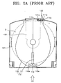
- a disk cartridge 100 includes a case 101 for accommodating a disk D, and a shutter 110 installed inside the case 101 to be capable of rotating and selectively open and shut an access aperture 102 formed in the case 101 so that a pickup (not shown) of a disk drive apparatus can access the disk D.
- a cover 103 seals a disk accommodating space to prevent contamination of the disk D by dust.
- the cover 103 is frequently omitted, because dust contamination has negligible effect on reading of the disk D, particularly following recent software developments.
- an opening lever 120 installed in the disk drive apparatus first presses a locking piece 111a to unlock a protrusion 111c of the shutter 110 from a groove 101a of the case 101.
- the opening lever 120 completely pushes an interference piece 111b to rotate the shutter 110.
- the shutter 110 includes first and second shutter portions 111 and 112 installed to be capable of rotating around each of left and right rotation shafts 110a and engaged with each other via an engagement gear portion 113.
- the second shutter portion 112 rotates counterclockwise, so that the first and second shutter portions 111 and 112 are separated widely, thus opening the aperture 102.
- a pickup (not shown) of the disk drive apparatus accesses the recording surface of the disk D through the opened aperture 102 to perform recording and/or reproduction of information.
- a torsion spring for elastically biasing the first shutter portion 111 counterclockwise that is, in a direction to close the aperture 102, is installed at the rotation shaft 110a between the first shutter portion 111 and the bottom surface of the case 101.
- the shutter 110 since the shutter 110 is installed inside the case 101 and the disk D is placed on the shutter 110, during opening and shutting operations of the shutter 110, the recording surface of the disk D (a lower surface of the disk) and the shutter 110 make a surface contact which may damage the disk recording surface, for example, a scratch.
- the scratch may act as a considerable external interference factor compared to the dust adhering to the recording surface. Therefore, a structure which can protect the recording surface of a disk during the opening and shutting operations of the shutter 110 is needed.
- EP 1 103 971, EP 0 358 442, EP 0 273 983, and Patent Abstracts of Japan, vol 1998, no. 01, 30 January 1998 & JP 09 251748A, 22 September 1997 disclose disk cartridges for accommodating a disc in which the disk is supported on a non-information area of the disk.
- a disk cartridge comprising: a case for accommodating a disk and including an access aperture; and a shutter installed inside the case for selectively opening and shutting the access aperture; a support portion arranged in use to support a non-information area of the disk characterised in that the support portion comprises:
- the support portion includes a flat portion arranged to support the outer circumferential non-information area of the disk when the shutter is in a closed state, and an inclined portion arranged to support the outer circumferential non-information area when the shutter is in an open state.
- a disk cartridge including a case for accommodating a disk and a shutter installed in the case to be capable of moving under a disk, for selectively opening/shutting an aperture formed in the case, the disk cartridge comprising a support portion protruding from the shutter to support a non-information area of the disk.
- FIGS 3 through 5 show a disk cartridge according to a first preferred embodiment of the present invention.
- a disk cartridge 200 includes a case 201 for accommodating a disk D, a shutter 210 for opening and shutting an aperture 202 formed in the case 201 under the disk D, and a cover 203 for covering the upper surface of the case 201 which is optional.
- the shutter 210 includes first and second shutter portions 211 and 212 symmetrically installed inside the case 201 to be capable of rotating.
- the aperture 202 is opened.
- Reference numeral 213 is an engagement gear portion for connecting the first and second shutter portions 211 and 212 to be capable of interacting. Accordingly, as the first shutter portion 211 rotates, the second shutter portion 212 is rotated by the engagement gear portion 213 in the opposite direction.
- a torsion spring for elastically biasing the first shutter portion 211 counterclockwise, that is, in a direction to close the aperture 202 is installed at a rotation shaft 210a between the first shutter portion 211 and the bottom surface of the case 201.
- Support portions 220 and 230 contacting the outermost edge of the disk D protrude from the first and second shutter portions 211 and 212. That is, the disk D includes a clamping area D1 at the inner circumferential side of the disk D, an information area D2 where information is recorded, and an edge portion D3 at the outer circumferential side of the information area D2.
- the support portions 220 and 230 support the edge portion D3 that is one of non-information areas to avoid contact between the information area D2 and the shutter 210.
- the support portion 220 at the upper side on the drawing, as shown in Figure 4, includes a flat portion 221 formed along the circumference of the disk D and an inclined portion 222 inclined toward the center of the disk D.
- the inclined portion 222 appears to contact the information area D2 of the disk D in Figure 5, in fact, the inclined portion 222 that is inclined does not contact the disk D. Instead, the inclined portion 222 supports the edge portion D3 of the disk D when the shutter 210 is in an open state. That is, since the rotation shaft 210a of the shutter 210 does not match the center of the disk D, when the shutter 210 is opened, the flat portion 221 is slightly deviated from the position for supporting the edge portion D3 of the disk D. Here, the inclined portion 222 supports the edge portion D3 instead of the flat portion 221.
- the opening lever 120 installed at the disk drive apparatus presses a locking piece 211a to unlock a protrusion 211c from a groove 201a and then pushes an interference piece 211b to rotate the first shutter portion 211 clockwise. Then, the second shutter portion 212 rotates counterclockwise by the engagement gear portion 213 and the aperture 202 is open between the first and second shutter portions 211 and 212.
- a support portion 240 for supporting the edge portion D3 of the disk D is directly formed on the bottom surface of the case 201, not on the shutter 210. That is, by forming the support portion 240 on the bottom surface of the case 201 that is fixed, not on the shutter 201 that is moving, to support the disk D, the contact between the shutter 210 and the disk D are fundamentally prevented.
- the support portion 240 is preferably formed at the position that does not interfere with a rotation area of the shutter 210.
- the opening lever 120 installed in the disk drive apparatus presses the locking piece 211a to unlock the protrusion 211c from the groove 201a and pushes the interference piece 211b to rotate the first shutter portion 211 clockwise. Then, the second shutter portion 212 rotates counterclockwise by the engagement gear portion 213 so that the aperture 202 is opened between the first and second shutter portions 211 and 212.
- the danger of the information area D2 of the recording surface being damaged is removed.
- the shutter 210 installed inside the case 201 is opened or shut, the information area D2 of the disk D can be prevented from being damaged.
- Figure 8 is an exploded perspective view of a disk cartridge not in accordance with the present invention.
- Figure 9 is a magnified view showing a portion indicated by reference letter B of Figure 8.
- Figure 10 is a magnified view showing a portion indicated by reference letter C of Figure 8.
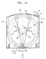
- Figure 11 is a plan view showing the state in which the shutter of the disk cartridge of Figure 8 is open.
- the disk cartridge 200 includes the case 201 for accommodating the disk D and the shutter 210 for opening or shutting the aperture 202 formed in the case 201 under the disk D.
- a plurality of support portions 250 contacting the clamping area D1 that is a non-information area disposed at the inner circumference of the disk D are provided at the case 201 to protrude therefrom.
- Guide channels 215 and 216 are formed in the shutter 201 to prevent contact and interference with the support portion 250 when the shutter 210 is opened and shut.
- the support portion 250 includes a protruding portion 251 extending from the case 201 and protruding above the upper surface of the shutter 210 and a contact portion 252 provided on the top of the protruding portion 251 to support the clamping area D1 of the disk D.
- the guide channel 215 is a lengthy channel having an arc-shape end portion formed in the shutter 210 so that, when the shutter 210 is opened or shut, the shutter 210 does not contact and interfere with the protruding portion 251.
- the guide channel 216 is a hole so that, when the shutter 210 is opened or shut, the shutter 210 does not contact and interfere with the protruding portion 251.
- the contact portion 252 is disposed above the upper surface of the shutter 210 and the length 1 of one side of the contact portion 252 is preferably formed to be greater than the width w of each of the guide channels 215 and 216. Accordingly, in the state in which the shutter 210 is closed, when a force applied from the outside to the shutter 210, that is, the shutter 210 is pressed toward the disk D, the shutter 210 is caught by the contact portion 252 so that a further pressing to the shutter 210 is prevented. Thus, since the shutter 210 does not contact the information area D2 of the disk D, the information area D2 of the disk D is prevented from being damaged.
- the shutter 210 When a user incidentally presses the shutter 210 during handling of the disk cartridge 200, the shutter 210 is caught by the support portion 252 and does not contact the information area D2 of the disk D.
- the information area D2 In the disk D having the clamping area D1, the information area D2 where information is recorded, and the edge portion D3 located outside the information area D2, since the clamping area D1 that is one of the non information areas is supported by the support portion 250, the information area D2 can avoid contacting the shutter 210. Also, when the shutter 210 is closed, the contact between the information area D2 and the shutter 210 can be prevented by the support portion 252.
- the support portion 252 has a rectangular shape various shapes such as cylinder having the same function can be used.
- the opening lever installed at the disk drive apparatus presses the locking piece 211a to unlock the protrusion 211c from the groove 201a. Then, the opening lever 120 pushes the interference piece 211b to rotate the first shutter portion 211 clockwise. Accordingly, the second shutter portion 212 is rotated counterclockwise by the engagement gear portion 213 so that the aperture 202 is opened between the first and second shutters 211 and 212.
- the support portion 252 contacts only the clamping area D1 of the disk D
- the information area D2 of the recording surface is hardly scratched during the opening and shutting operations of the shutter 210.
- the shutter 210 closes the aperture 202 to return to the state of Figure 8 since the closing operation is performed in the state in which the support portion 252 contacts only the clamping area D1 of the disk D, the information area D2 of the disk D can be stably kept.
- the disk cartridge described herein has many advantages.
- the support portion formed on the shutter or the case contacts only the non-information area of the disk, the information area of the disk can be stably kept during the operation of the shutter to open and shut the aperture.
- the information area of the disk can be kept free of damage.
Landscapes
- Feeding And Guiding Record Carriers (AREA)
- Packaging For Recording Disks (AREA)
Claims (2)
- Eine Diskette, umfassend:ein Gehäuse (201) zum Aufnehmen einer Disk (D) und eine Zugriffsöffnung (202) einschließend; undeinen Verschluss (219), der innerhalb des Gehäuses zum wahlweisen Öffnen und Schließen der Zugriffsöffnung (202) angebracht ist;ein Trägerteil (220, 230), das im Gebrauch so angeordnet ist, dass es einen Nichtinformationsbereich (D3) der Disk (D) stützt;dadurch gekennzeichnet, dassdas Trägerteil erste und zweite Trägerteile (220, 230) umfasst, die auf ersten und zweiten Verschlussteilen (211, 212) ausgebildet sind und von diesen hervorragen, die jeweils so angeordnet sind, dass sie einen äußeren peripheren Nichtinformationsbereich (D3) der Disk (D) stützen.
- Die Diskette von Anspruch 1, in der das Trägerteil (220) ein flaches Teil (221) einschließt, das so angeordnet ist, dass es den äußeren peripheren Nichtinformationsbereich (D3) der Disk (D) stützt, wenn sich der Verschluss in einem geschlossenen Zustand befindet, und ein geneigtes Teil (222), das so angeordnet ist, dass es den äußeren peripheren Nichtinformationsbereich (D3) stützt, wenn sich der Verschluss (210) in einem geöffneten Zustand befindet, einschließt.
Applications Claiming Priority (4)
| Application Number | Priority Date | Filing Date | Title |
|---|---|---|---|
| KR1020010064366A KR100823249B1 (ko) | 2001-10-18 | 2001-10-18 | 디스크 카트리지 |
| KR2001064366 | 2001-10-18 | ||
| KR1020010066020A KR100823251B1 (ko) | 2001-10-25 | 2001-10-25 | 디스크 카트리지 |
| KR2001066020 | 2001-10-25 |
Publications (3)
| Publication Number | Publication Date |
|---|---|
| EP1304699A2 EP1304699A2 (de) | 2003-04-23 |
| EP1304699A3 EP1304699A3 (de) | 2003-08-27 |
| EP1304699B1 true EP1304699B1 (de) | 2007-05-09 |
Family
ID=26639407
Family Applications (1)
| Application Number | Title | Priority Date | Filing Date |
|---|---|---|---|
| EP02257086A Expired - Lifetime EP1304699B1 (de) | 2001-10-18 | 2002-10-11 | Plattenkassette |
Country Status (6)
| Country | Link |
|---|---|
| US (1) | US7143427B2 (de) |
| EP (1) | EP1304699B1 (de) |
| JP (1) | JP3818950B2 (de) |
| CN (1) | CN100339904C (de) |
| DE (1) | DE60220005T2 (de) |
| TW (1) | TWI241562B (de) |
Families Citing this family (7)
| Publication number | Priority date | Publication date | Assignee | Title |
|---|---|---|---|---|
| WO2002056313A1 (en) | 2001-01-12 | 2002-07-18 | Matsushita Electric Industrial Co., Ltd. | Disc cartridge |
| US6910219B2 (en) | 2001-07-06 | 2005-06-21 | Matsushita Electric Industrial Co., Ltd. | Disc cartridge |
| US7124423B2 (en) * | 2002-02-20 | 2006-10-17 | Samsung Electronics Co., Ltd. | Disk cartridge to protect an information area of a disk from being contaminated |
| KR100699644B1 (ko) | 2003-04-09 | 2007-03-23 | 마츠시타 덴끼 산교 가부시키가이샤 | 디스크 카트리지, 데이터 저장 매체 및 디스크 드라이브 |
| DE602004022341D1 (de) * | 2003-06-23 | 2009-09-10 | Sony Corp | Aufzeichnungsmediumgehäuse |
| JP2005267826A (ja) * | 2004-02-18 | 2005-09-29 | Sony Corp | 記録媒体ドライブ装置、これを備えた電子機器及び記録媒体カートリッジ |
| EP2011119B1 (de) * | 2006-04-27 | 2011-12-14 | Panasonic Corporation | Datenträgerkassette |
Family Cites Families (21)
| Publication number | Priority date | Publication date | Assignee | Title |
|---|---|---|---|---|
| JPS60159575A (ja) | 1984-01-27 | 1985-08-21 | 三菱電機株式会社 | 冷蔵庫 |
| EP0273983B1 (de) * | 1986-07-04 | 1992-03-11 | Sony Corporation | Plattenkassette |
| JPS6355269A (ja) | 1986-08-23 | 1988-03-09 | 株式会社長谷工コーポレーション | 鉄筋継手の仮設保持具 |
| DE68921270T2 (de) * | 1988-09-09 | 1995-07-13 | Canon Kk | Plattenkassette. |
| JPH03134860A (ja) | 1989-10-20 | 1991-06-07 | Clarion Co Ltd | ディスクローディング機構 |
| US5717684A (en) * | 1990-01-29 | 1998-02-10 | Dai Nippon Insatsu Kabushiki Kaisha | Disk cartridge having chamfered wall portion |
| JP2618790B2 (ja) | 1992-07-27 | 1997-06-11 | 大日本スクリーン製造株式会社 | 金属薄板搬送装置 |
| EP0665549B1 (de) * | 1994-01-28 | 1999-04-28 | Sony Corporation | Plattenkassette |
| CN1088893C (zh) * | 1994-12-29 | 2002-08-07 | 索尼公司 | 磁盘盒 |
| JPH09245452A (ja) * | 1996-03-07 | 1997-09-19 | Sony Corp | ディスクカートリッジ |
| JPH09251748A (ja) * | 1996-03-13 | 1997-09-22 | Sony Corp | ディスクカートリッジ |
| US5898664A (en) * | 1996-03-19 | 1999-04-27 | Sony Corporation | Position controlling mechanism for a disc cartridge |
| JPH1064224A (ja) | 1996-08-26 | 1998-03-06 | Sony Corp | リムーバブルディスクカートリッジ |
| JP3480220B2 (ja) | 1997-02-17 | 2003-12-15 | 三菱化学株式会社 | ディスク収納用カートリッジ |
| US5974026A (en) * | 1997-11-14 | 1999-10-26 | Castlewood Systems, Inc. | Anti-rattle mechanism for a removable video disk cartridge |
| JP4103257B2 (ja) * | 1998-07-13 | 2008-06-18 | ソニー株式会社 | ディスクカートリッジ |
| JP2001148175A (ja) * | 1999-11-24 | 2001-05-29 | Sony Corp | ディスクカートリッジ |
| JP2001229643A (ja) * | 2000-02-14 | 2001-08-24 | Sony Corp | ディスクカートリッジ |
| JP2002056313A (ja) | 2000-08-09 | 2002-02-20 | Nec Corp | 電子データ提供システムおよび方法 |
| WO2002056313A1 (en) * | 2001-01-12 | 2002-07-18 | Matsushita Electric Industrial Co., Ltd. | Disc cartridge |
| KR100788651B1 (ko) * | 2002-01-10 | 2007-12-26 | 삼성전자주식회사 | 디스크 카트리지 |
-
2002
- 2002-09-05 TW TW091120251A patent/TWI241562B/zh not_active IP Right Cessation
- 2002-09-27 CN CNB021444226A patent/CN100339904C/zh not_active Expired - Fee Related
- 2002-10-07 JP JP2002294092A patent/JP3818950B2/ja not_active Expired - Fee Related
- 2002-10-11 DE DE60220005T patent/DE60220005T2/de not_active Expired - Lifetime
- 2002-10-11 EP EP02257086A patent/EP1304699B1/de not_active Expired - Lifetime
- 2002-10-18 US US10/273,366 patent/US7143427B2/en not_active Expired - Fee Related
Also Published As
| Publication number | Publication date |
|---|---|
| JP3818950B2 (ja) | 2006-09-06 |
| CN1412768A (zh) | 2003-04-23 |
| DE60220005D1 (de) | 2007-06-21 |
| DE60220005T2 (de) | 2008-01-10 |
| EP1304699A2 (de) | 2003-04-23 |
| US7143427B2 (en) | 2006-11-28 |
| US20030128653A1 (en) | 2003-07-10 |
| EP1304699A3 (de) | 2003-08-27 |
| JP2003178544A (ja) | 2003-06-27 |
| TWI241562B (en) | 2005-10-11 |
| CN100339904C (zh) | 2007-09-26 |
Similar Documents
| Publication | Publication Date | Title |
|---|---|---|
| US20030053409A1 (en) | Disc cartridge | |
| EP0245457B1 (de) | Aufnahmeplattenanordnung | |
| EP1304699B1 (de) | Plattenkassette | |
| CA2438299A1 (en) | Disc cartridge | |
| AU2002359081B2 (en) | Disk cartridge | |
| US7124423B2 (en) | Disk cartridge to protect an information area of a disk from being contaminated | |
| US7263706B2 (en) | Disk cartridge and disk player using the same | |
| AU2002359081A1 (en) | Disk cartridge | |
| EP1476868B1 (de) | Datenträgerkassette | |
| US7089574B2 (en) | Disk cartridge | |
| KR100823251B1 (ko) | 디스크 카트리지 | |
| KR100823249B1 (ko) | 디스크 카트리지 | |
| KR20000068722A (ko) | 디스크 카트리지 | |
| EP1476867A1 (de) | Datenträgerkassette | |
| KR100823250B1 (ko) | 디스크 카트리지 | |
| HK1072653B (en) | Disk cartridge |
Legal Events
| Date | Code | Title | Description |
|---|---|---|---|
| PUAI | Public reference made under article 153(3) epc to a published international application that has entered the european phase |
Free format text: ORIGINAL CODE: 0009012 |
|
| 17P | Request for examination filed |
Effective date: 20021025 |
|
| AK | Designated contracting states |
Designated state(s): AT BE BG CH CY CZ DE DK EE ES FI FR GB GR IE IT LI LU MC NL PT SE SK TR |
|
| AX | Request for extension of the european patent |
Extension state: AL LT LV MK RO SI |
|
| PUAL | Search report despatched |
Free format text: ORIGINAL CODE: 0009013 |
|
| RIN1 | Information on inventor provided before grant (corrected) |
Inventor name: CHUNG, CHONG-SAM Inventor name: EUM, JAE-YONG Inventor name: KANG, HEUI-JONG Inventor name: LEE, YONG-HOON Inventor name: CHOI, HAN-KOOK Inventor name: YIM, HONG-KYUN |
|
| AK | Designated contracting states |
Designated state(s): AT BE BG CH CY CZ DE DK EE ES FI FR GB GR IE IT LI LU MC NL PT SE SK TR |
|
| AX | Request for extension of the european patent |
Extension state: AL LT LV MK RO SI |
|
| AKX | Designation fees paid |
Designated state(s): DE FR GB NL |
|
| 17Q | First examination report despatched |
Effective date: 20050216 |
|
| GRAP | Despatch of communication of intention to grant a patent |
Free format text: ORIGINAL CODE: EPIDOSNIGR1 |
|
| GRAS | Grant fee paid |
Free format text: ORIGINAL CODE: EPIDOSNIGR3 |
|
| GRAA | (expected) grant |
Free format text: ORIGINAL CODE: 0009210 |
|
| AK | Designated contracting states |
Kind code of ref document: B1 Designated state(s): DE FR GB NL |
|
| REG | Reference to a national code |
Ref country code: GB Ref legal event code: FG4D |
|
| REF | Corresponds to: |
Ref document number: 60220005 Country of ref document: DE Date of ref document: 20070621 Kind code of ref document: P |
|
| ET | Fr: translation filed | ||
| PLBE | No opposition filed within time limit |
Free format text: ORIGINAL CODE: 0009261 |
|
| STAA | Information on the status of an ep patent application or granted ep patent |
Free format text: STATUS: NO OPPOSITION FILED WITHIN TIME LIMIT |
|
| 26N | No opposition filed |
Effective date: 20080212 |
|
| PGFP | Annual fee paid to national office [announced via postgrant information from national office to epo] |
Ref country code: NL Payment date: 20140924 Year of fee payment: 13 |
|
| PGFP | Annual fee paid to national office [announced via postgrant information from national office to epo] |
Ref country code: GB Payment date: 20140924 Year of fee payment: 13 |
|
| PGFP | Annual fee paid to national office [announced via postgrant information from national office to epo] |
Ref country code: DE Payment date: 20140924 Year of fee payment: 13 Ref country code: FR Payment date: 20140925 Year of fee payment: 13 |
|
| REG | Reference to a national code |
Ref country code: DE Ref legal event code: R119 Ref document number: 60220005 Country of ref document: DE |
|
| GBPC | Gb: european patent ceased through non-payment of renewal fee |
Effective date: 20151011 |
|
| REG | Reference to a national code |
Ref country code: NL Ref legal event code: MM Effective date: 20151101 |
|
| PG25 | Lapsed in a contracting state [announced via postgrant information from national office to epo] |
Ref country code: DE Free format text: LAPSE BECAUSE OF NON-PAYMENT OF DUE FEES Effective date: 20160503 Ref country code: GB Free format text: LAPSE BECAUSE OF NON-PAYMENT OF DUE FEES Effective date: 20151011 |
|
| REG | Reference to a national code |
Ref country code: FR Ref legal event code: ST Effective date: 20160630 |
|
| PG25 | Lapsed in a contracting state [announced via postgrant information from national office to epo] |
Ref country code: FR Free format text: LAPSE BECAUSE OF NON-PAYMENT OF DUE FEES Effective date: 20151102 Ref country code: NL Free format text: LAPSE BECAUSE OF NON-PAYMENT OF DUE FEES Effective date: 20151101 |