EP1304706B1 - Atténuateur rotatif compact - Google Patents
Atténuateur rotatif compact Download PDFInfo
- Publication number
- EP1304706B1 EP1304706B1 EP02023547A EP02023547A EP1304706B1 EP 1304706 B1 EP1304706 B1 EP 1304706B1 EP 02023547 A EP02023547 A EP 02023547A EP 02023547 A EP02023547 A EP 02023547A EP 1304706 B1 EP1304706 B1 EP 1304706B1
- Authority
- EP
- European Patent Office
- Prior art keywords
- input
- output
- housing
- terminal board
- terminal
- Prior art date
- Legal status (The legal status is an assumption and is not a legal conclusion. Google has not performed a legal analysis and makes no representation as to the accuracy of the status listed.)
- Expired - Lifetime
Links
Images


Classifications
-
- H—ELECTRICITY
- H01—ELECTRIC ELEMENTS
- H01H—ELECTRIC SWITCHES; RELAYS; SELECTORS; EMERGENCY PROTECTIVE DEVICES
- H01H19/00—Switches operated by an operating part which is rotatable about a longitudinal axis thereof and which is acted upon directly by a solid body external to the switch, e.g. by a hand
-
- H—ELECTRICITY
- H01—ELECTRIC ELEMENTS
- H01P—WAVEGUIDES; RESONATORS, LINES, OR OTHER DEVICES OF THE WAVEGUIDE TYPE
- H01P1/00—Auxiliary devices
- H01P1/22—Attenuating devices
- H01P1/225—Coaxial attenuators
Definitions
- the present invention relates to a rotary attenuator device.
- Each rotary attenuator device 50 has a disk-shaped terminal board 52 which can rotate in a housing 51.
- the disk-shaped terminal board is driven by stepwise rotational movement for a specified angle through operating a dial (not illustrated) mounted at a driving shaft 53 which protrudes outside of the housing 51.
- Plural pairs of input and output terminals are locally arranged on one side of the terminal board 52.
- an input coaxial connector 54 and an output coaxial connector 55 are provided on a side of the housing 52, which is opposite to the side where the driving shaft 53 is provided.
- contact shoes 56 and 57 respectively contact with input terminal 58 and output terminals 59 of a pair in the housing, and come to respectively contact with input terminals 58' and output terminals 59' of another pair once the terminal board rotates stepwise in one direction or another direction.
- the contact shoes 56 and 57 are respectively connected to the central conductor of the connectors 54 and 55.
- the contact shoes 56 and 57 of the input and output coaxial connectors 54 and 55 are made similar each other.
- the contact shoe 56 for example, is made by bending a metal sheet band, such that the sheet surface of the bent part is parallel to the surface of the non-bent part. Therefore, it looks like a U-shape skid for the shaft 56A, which is connected to the central conductor.
- the contact shoe 54 extends along circumferential direction on the terminal board, e.g. a direction towards its adjacent input terminal 58'.
- the contact shoe 54 elastically contacts with the input terminal by its elasticity, and comes to contact with the adjacent input terminal with its rounded end, e.g. the rounded bottom part of the U-shape.
- Such contact shoe is also provided to the output coaxial connector.
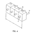
- the pair of input and output terminals 58 and 59 respectively contact with the contact shoes 56 and 57 at one side of the terminal board, e.g. on the same side of the terminal board 52, the pair of the input and output terminals 58 and 59 cannot be provided too close to each other. Therefore, the input and output coaxial connectors 54 and 55 need to be arranged in more distant positions. Accordingly, the distance between the input terminal and the output terminal needs to be set relatively large. If plural pairs of both terminals are arranged along the circumference on the terminal board 52, the terminal board 52 becomes large. Consequently, if a plurality of the rotary attenuator devices 50 are arranged as illustrated in Fig. 5, the total width L becomes extremely large. That is, it is not avoidable that the electronic device, in which this rotary attenuator device is used, becomes even larger.
- the contact shoe of Fig. 7 since the possible elastic displacement of the conventional contact shoe of Fig. 7 is small, the allowable amount for errors in the displacement is small. In other words, it is hard to stabilize the contact. Furthermore, because of its shape, the contact shoe smoothly contacts with the terminal when the terminal board rotates in one rotational direction, but when the terminal board rotates in the opposite direction, the contact shoe is often caught by the terminal and also, the contact tends to be unstable.
- the rotary attenuator has a disk-type terminal board 3 in a hollow chamber 2 of a housing 1 which is a block-shaped metal. It is not illustrated in the figure, but the housing 1 itself can be disassembled into several parts, so that the attenuator device can be assembled by first, placing the terminal board 3 in the hollow chamber 2, as illustrated in Fig. 1, and then covering the terminal board.
- the housing 1 has outer surfaces 4, 5, and 6, which are respectively vertical to axes 4A, 5A, and 6A.
- the axes 4A, 5A, and 6A are vertical or parallel each other in a paper surface of Fig. 1.
- the housing 1 has a pair of flat outer surfaces 7, 8, which are parallel to the paper surface of Fig. 1 (In Fig.
- the housing 1 has substantially rectangular parallelepiped block shape.
- the outer surface does not have to be flat, and can be optionally any shape.
- Coaxial connectors 9 and 10 are respectively attached to the outer surfaces 4 and 5 of the housing 1. As for those coaxial connectors 9 and 10, one is used as input coaxial connector, and the other is used as the output coaxial connector.
- the coaxial connectors 9 and 10 respectively have screw portions 9A and 10A, respectively, to connect with the coaxial cable outside the housing.
- the coaxial connectors 9, 10 have central conductors 9B, 10B protruding into the housing.
- the central conductors 9B, 10B hold the contact shoes 11, 12.
- the contact shoes are described below in detail.
- the driving shaft 13 extends outward from the outer surface 6 of the housing 1, and the dial (not illustrated) can be attached outside the housing to rotationally drive the driving shaft 13 around the axis 6A.
- the driving shaft 13 also protrudes into the housing 1, and supports the terminal board 3 at its center position.
- the mutual positioning and attachment of the terminal board 3 and the driving shaft 13 are done by the spacer 14, the nut 15, and so on.
- the driving shaft 13 and the housing 1 are electrically connected by a spring washer 16 and a sliding member 17.
- the terminal board 3 is disk-shaped, and has a D-shaped shaft, hole 3A at its center, in which the driving shaft 13 goes through.
- the driving shaft 13 is stopped in the circumferential direction by the straight inner area 3A1 of the D-shaped shaft hole.
- a plurality of holes 18 is provided along the circumference of the shaft hole 3A, and used for putting wiring through from both sides of the terminal board if required.
- a plurality of pairs of terminal holes 19A and 19B are provided along the outer circumference of the terminal board 3.
- the terminal 20A is provided at one terminal hole 19A, extruding outward from one side of the terminal hoard, while the terminal 20B is provided at the other terminal hole 19B, extruding outward from the other side of the terminal board.
- Conductive surface areas 22, 23, as illustrated by slanting lines in Fig. 2, are printed in areas on the terminal board, where the terminals 20A, 20B are to be attached.
- the conductive surface area 23 on a surface where the terminal 20B is attached has an extension part 24, which extends inward in a radial direction.
- Electronic part 29 required for an attenuator, such as resistance, is arranged and connects between the extension part 24 on the side of the terminal 20B and the extension part 24 on the side of the terminal 20A, and between the extension part 24 and the central conductive surface area 25.
- Electrical properties, such as resistance, of the electronic parts arranged to each pair of terminals are different among the electronic devices, and the properties of the input/output terminals gradually change by stepwise rotation of the driving shaft 13 for every contact of the contact shoes with the pair of terminals.
- the contact shoes 11, 12 held by the central conductors 9B, 10B of the coaxial connectors 9, 10 are attached to one end of the elastic arm 27, 28, which extends in a radial direction of the terminal board, being angled from the surface of the terminal board.
- the other ends of the elastic arms 27, 28 are connected and retained to the central conductors 9B, 10B.
- the elastic arm 27 is positioned inward in the radial direction, and bent at its middle position such that one end is vertical to the other end (here, the elastic arm can be located outward in the radial direction).
- the elastic arm 28 is positioned outward in the radial direclion, and slightly bent, but extends in the radial direction of the terminal board 3.
- the contact shoes 11, 12 attached to one end of the elastic arms 27, 28 are the same each other. As illustrated in Fig. 3, the contact shoe 11 contacts with the terminal 20A, and is shaped like a wave along the circumferential direction with its ends up in the circumferential direction. Because of this shape, the contact shoe can easily move onto the adjacent terminal at the time of moving towards the adjacent terminal. Accordingly, the contact shoe 11 surely contact with terminal even when the terminal to contact is changed by the stepwise rotational movement of the terminal board 3, and stop at the normal contact position so as to maintain its contacting condition.
- the width of the contact length in the circumferential direction is larger than the diameter of the head part of the terminal, but is designed not to contact with the adjacent terminal when the lower surface of the dent 11B contacts with one terminal at normal position.
- the amount of attenuation can be selecbed by changing the resistance between the input/output terminals or the like through stepwise rotation of the driving shaft 13 under the condition where the input and output coaxial connectors 9, 10 are connected to coaxial cables.
- the distance between those terminals is smaller than before, so that the radius of the terminal board can be smaller. That is, the width of the attenuator device can be smaller. Also, the width of the contact shoe in circumferental direction can by smaller by contacting the contact shoe with the terminal in the radial direction of the terminal board, so that device can be smaller even on this point. Furthermore, since the axes of the coaxial connectors and the driving shaft are supposed to be all located in one surface (hypothetical surface), the size in the above-described width direction can be smaller also in this point.
- the attenuator device of the present invention can be used alone, but it can be used combining several of them. In this case, the features of the present invention can be fully used.
- the total width L is extremely small due to the narrow width of each attenuator, so that the electronic device, in which those attenuators are used, can be made small in the direction of arranging the attenuators.
- the distance between the input terminal and the output terminal of the pair can be shorter.
- the contact shoe is designed to contact by extending in the radial direction of the terminal board, there is no space required for holding the contact shoe in the circumferential direction.
- the distance between the pairs of the input terminal and the output terminal can be short when plural pairs of terminals are arranged on the terminal board, as well as the distance between the input terminal and the output terminal of the pair is maintained small.
- the size in the radial direction of the terminal board can be extremely small; therefore, the attenuator device can be made small.
- the size of the device can be even smaller.
- plural attenuators are arranged, a large effect can be expected if they are arranged by contacting each other by their outer surfaces.
Landscapes
- Coupling Device And Connection With Printed Circuit (AREA)
- Adjustable Resistors (AREA)
Claims (6)
- Dispositif atténuateur rotatif comprenant:un corps (1) ;une plaque à bornes en forme de disque (3) prévue dans le dit corps (1) ;au moins une paire constituée d'une borne d'entrée et d'une borne de sortie (20A, 20B) qui est située le long de la région circonférentielle de la dite plaque à bornes (3) ;au moins un composant électronique (29) qui est placé entre la dite borne d'entrée et la dite borne de sortie (20A, 20B) et qui est relié à la dite plaque à bornes (3) ;un arbre d'entraînement (13) accouplé à un centre de la dite plaque à bornes (3) dans le dit corps (1), le dit arbre d'entraînement (13) étant perpendiculaire à une surface de la dite plaque à bornes (3) et faisant saillie à l'extérieur par rapport au dit corps (1) à l'autre extrémité, et étant tenu de manière à tourner librement ;des patins de contact d'entrée et de sortie (11, 12) élastiquement en contact avec les dites bornes d'entrée et de sortie (20A, 20B), respectivement, les dits patins de contact d'entrée et de sortie (11, 12) étant prévus de manière à glisser librement ; etdes connecteurs coaxiaux d'entrée et de sortie (9, 10) supportés par le dit corps (1) et ayant un conducteur central (9B, 10B) qui s'étend à l'intérieur du dit corps (1), dans lequelles dits patins de contact d'entrée et de sortie (11, 12) sont attachés de façon à venir en contact avec les bornes d'entrée et de sortie (20A, 20B) correspondantes sur des côtés différents de la dite plaque à bornes (3).
- Dispositif atténuateur rotatif selon la revendication 1, comprenant en outre des bras élastiques (27, 28) pour supporter les dits patins de contact d'entrée et de sortie (11, 12) à des premières extrémités, dans lequel les dits bras élastiques (27, 28) sont des éléments en porte-à-faux s'étendant dans une direction radiale de la dite plaque à bornes (3), et ils sont connectés et maintenus aux dits conducteurs centraux (9B, 10B) des dits connecteurs coaxiaux d'entrée et de sortie (9, 10), aux autres extrémités.
- Dispositif atténuateur rotatif selon la revendication 1, dans lequel le dit corps (1) présente deux surfaces extérieures planes (7, 8) qui sont mutuellement parallèles et opposées, et chaque axe du dit arbre d'entraînement (13), du dit connecteur coaxial d'entrée et du dit connecteur coaxial de sortie (9, 10) est dans une surface parallèle aux dites deux surfaces extérieures (7, 8).
- Dispositif atténuateur rotatif selon la revendication 1, dans lequel les dits patins de contact d'entrée et de sortie (11, 12) sont prévus à une extrémité de chaque dit bras élastique (27, 28) qui est en porte-à-faux s'étendant dans une direction radiale de la dite plaque à bornes (3), le dit bras élastique (27, 28) étant en contact et en connexion avec le dit conducteur central (9B, 10B) des dits connecteurs coaxiaux d'entrée et de sortie (9, 10) à l'autre extrémité, le dit corps (1) présente deux surfaces extérieures planes (7, 8), chaque axe du dit arbre d'entraînement (13), du dit connecteur coaxial d'entrée et du dit connecteur coaxial de sortie (9, 10) est dans une surface parallèle aux dites deux surfaces extérieures (7, 8).
- Dispositif atténuateur rotatif selon la revendication 1, 3 et 4, dans lequel le dit arbre d'entraînement (13), qui est accouplé à un centre de la dite plaque à bornes à sa première extrémité, de façon à être perpendiculaire à une surface de la dite plaque à bornes, fait saillie vers l'extérieur par rapport au dit corps (1) à l'autre extrémité, et il est maintenu de façon à tourner librement.
- Dispositif atténuateur rotatif selon la revendication 3, dans lequel le dit corps (1) est un bloc sensiblement en forme de parallélépipède rectangle, il présente des surfaces extérieures (4, 6) qui sont mutuellement perpendiculaires, et il présente deux surfaces extérieures optionnelles parallèles à la dite surface extérieure du dit corps (7, 8), et les dits connecteurs coaxiaux sont respectivement situés à l'endroit des dites surfaces extérieures du dit corps (1).
Applications Claiming Priority (2)
| Application Number | Priority Date | Filing Date | Title |
|---|---|---|---|
| JP2001323773 | 2001-10-22 | ||
| JP2001323773A JP3696540B2 (ja) | 2001-10-22 | 2001-10-22 | ロータリアッテネータ装置 |
Publications (3)
| Publication Number | Publication Date |
|---|---|
| EP1304706A2 EP1304706A2 (fr) | 2003-04-23 |
| EP1304706A3 EP1304706A3 (fr) | 2005-06-29 |
| EP1304706B1 true EP1304706B1 (fr) | 2007-09-12 |
Family
ID=19140613
Family Applications (1)
| Application Number | Title | Priority Date | Filing Date |
|---|---|---|---|
| EP02023547A Expired - Lifetime EP1304706B1 (fr) | 2001-10-22 | 2002-10-22 | Atténuateur rotatif compact |
Country Status (6)
| Country | Link |
|---|---|
| US (1) | US6762373B2 (fr) |
| EP (1) | EP1304706B1 (fr) |
| JP (1) | JP3696540B2 (fr) |
| KR (1) | KR100573552B1 (fr) |
| CN (1) | CN1244114C (fr) |
| DE (1) | DE60222359T2 (fr) |
Families Citing this family (2)
| Publication number | Priority date | Publication date | Assignee | Title |
|---|---|---|---|---|
| JP2005243687A (ja) * | 2004-02-24 | 2005-09-08 | Alps Electric Co Ltd | 回転型可変抵抗器 |
| CN115706382A (zh) * | 2021-08-10 | 2023-02-17 | 罗森伯格亚太电子有限公司 | 一种可切换式射频连接器组件 |
Family Cites Families (9)
| Publication number | Priority date | Publication date | Assignee | Title |
|---|---|---|---|---|
| US2481649A (en) * | 1945-04-25 | 1949-09-13 | Daven Company | Attenuator assembly |
| US2484126A (en) * | 1948-05-04 | 1949-10-11 | Daven Company | Attenuator assembly |
| US2601372A (en) * | 1948-08-11 | 1952-06-24 | Gabriel Co | Rotary coaxial switch |
| US3303296A (en) * | 1964-12-08 | 1967-02-07 | Mc Graw Edison Co | Attenuator with improved housing structure |
| US3652812A (en) * | 1970-09-28 | 1972-03-28 | Westinghouse Electric Corp | Tap changer switch with radial pressurized movable contact structure |
| US3940584A (en) * | 1974-06-19 | 1976-02-24 | Arvin Industries, Inc. | Coaxial switch for high frequency signals |
| DE2650018C2 (de) * | 1976-01-28 | 1983-12-08 | Alps Electric Co., Ltd., Tokyo | Elektrische Abschwächereinrichtung für Tonwiedergabesysteme |
| JP3337999B2 (ja) | 1999-04-07 | 2002-10-28 | 日本アンテナ株式会社 | ロータリー式アッテネータ |
| US6353195B1 (en) * | 1999-11-04 | 2002-03-05 | Spencer G. Stanfield | Mechanism for interrupting current flow through two electrical cables |
-
2001
- 2001-10-22 JP JP2001323773A patent/JP3696540B2/ja not_active Expired - Fee Related
-
2002
- 2002-10-19 KR KR1020020064033A patent/KR100573552B1/ko not_active Expired - Fee Related
- 2002-10-21 US US10/273,920 patent/US6762373B2/en not_active Expired - Fee Related
- 2002-10-22 CN CNB021469202A patent/CN1244114C/zh not_active Expired - Fee Related
- 2002-10-22 EP EP02023547A patent/EP1304706B1/fr not_active Expired - Lifetime
- 2002-10-22 DE DE60222359T patent/DE60222359T2/de not_active Expired - Fee Related
Non-Patent Citations (1)
| Title |
|---|
| None * |
Also Published As
| Publication number | Publication date |
|---|---|
| KR100573552B1 (ko) | 2006-04-25 |
| CN1244114C (zh) | 2006-03-01 |
| US20030075421A1 (en) | 2003-04-24 |
| EP1304706A2 (fr) | 2003-04-23 |
| CN1414574A (zh) | 2003-04-30 |
| DE60222359T2 (de) | 2008-06-12 |
| DE60222359D1 (de) | 2007-10-25 |
| KR20030033940A (ko) | 2003-05-01 |
| JP2003133106A (ja) | 2003-05-09 |
| JP3696540B2 (ja) | 2005-09-21 |
| US6762373B2 (en) | 2004-07-13 |
| EP1304706A3 (fr) | 2005-06-29 |
Similar Documents
| Publication | Publication Date | Title |
|---|---|---|
| EP2885843B1 (fr) | Contact électrique | |
| CN1126212C (zh) | 可以构形的接地面 | |
| US7802995B2 (en) | Rotatable connector connecting two flexible printed circuit boards | |
| EP0225400B1 (fr) | Broche de contact | |
| JP6290391B2 (ja) | プラグインコネクタ | |
| EP2665128A1 (fr) | Élément de contact IDC destiné à une fiche électrique | |
| EP3469660B1 (fr) | Connecteur avec section de base asymétrique | |
| EP1304706B1 (fr) | Atténuateur rotatif compact | |
| EP1420489B1 (fr) | Connecteur à charnière et carte à circuit imprimé connectée à celui-ci | |
| JP4428765B2 (ja) | モジュラジャック | |
| US5997339A (en) | Cable connection | |
| US7371094B1 (en) | Aligned contact group and electrical connector for flexible substrate | |
| US20240072464A1 (en) | Electrical plug-in connection and printed circuit board arrangement | |
| JP2019012701A (ja) | コネクタ | |
| JP2017204487A (ja) | コネクタ | |
| JPS586099Y2 (ja) | 高周波切換スイッチ | |
| KR20050080645A (ko) | 가변형 커넥터 | |
| JP2003133106A5 (fr) | ||
| CN101111975A (zh) | 带有可旋转的连接器承载件的电路连接装置 | |
| JP2004259543A (ja) | コネクタ | |
| JP2006004802A (ja) | 小型回転コネクタ | |
| JP2000149692A (ja) | 接片機構 |
Legal Events
| Date | Code | Title | Description |
|---|---|---|---|
| PUAI | Public reference made under article 153(3) epc to a published international application that has entered the european phase |
Free format text: ORIGINAL CODE: 0009012 |
|
| AK | Designated contracting states |
Designated state(s): AT BE BG CH CY CZ DE DK EE ES FI FR GB GR IE IT LI LU MC NL PT SE SK TR |
|
| AX | Request for extension of the european patent |
Extension state: AL LT LV MK RO SI |
|
| RIC1 | Information provided on ipc code assigned before grant |
Ipc: 7H 01H 19/04 B Ipc: 7H 01C 10/48 B Ipc: 7H 01P 1/22 B Ipc: 7H 01C 10/32 A |
|
| PUAL | Search report despatched |
Free format text: ORIGINAL CODE: 0009013 |
|
| AK | Designated contracting states |
Kind code of ref document: A3 Designated state(s): AT BE BG CH CY CZ DE DK EE ES FI FR GB GR IE IT LI LU MC NL PT SE SK TR |
|
| AX | Request for extension of the european patent |
Extension state: AL LT LV MK RO SI |
|
| 17P | Request for examination filed |
Effective date: 20050915 |
|
| AKX | Designation fees paid |
Designated state(s): DE FR GB |
|
| GRAP | Despatch of communication of intention to grant a patent |
Free format text: ORIGINAL CODE: EPIDOSNIGR1 |
|
| GRAS | Grant fee paid |
Free format text: ORIGINAL CODE: EPIDOSNIGR3 |
|
| GRAA | (expected) grant |
Free format text: ORIGINAL CODE: 0009210 |
|
| AK | Designated contracting states |
Kind code of ref document: B1 Designated state(s): DE FR GB |
|
| REG | Reference to a national code |
Ref country code: GB Ref legal event code: FG4D |
|
| REF | Corresponds to: |
Ref document number: 60222359 Country of ref document: DE Date of ref document: 20071025 Kind code of ref document: P |
|
| PGFP | Annual fee paid to national office [announced via postgrant information from national office to epo] |
Ref country code: DE Payment date: 20071130 Year of fee payment: 6 |
|
| ET | Fr: translation filed | ||
| PGFP | Annual fee paid to national office [announced via postgrant information from national office to epo] |
Ref country code: GB Payment date: 20071109 Year of fee payment: 6 Ref country code: FR Payment date: 20071107 Year of fee payment: 6 |
|
| PLBE | No opposition filed within time limit |
Free format text: ORIGINAL CODE: 0009261 |
|
| STAA | Information on the status of an ep patent application or granted ep patent |
Free format text: STATUS: NO OPPOSITION FILED WITHIN TIME LIMIT |
|
| 26N | No opposition filed |
Effective date: 20080613 |
|
| GBPC | Gb: european patent ceased through non-payment of renewal fee |
Effective date: 20081022 |
|
| REG | Reference to a national code |
Ref country code: FR Ref legal event code: ST Effective date: 20090630 |
|
| PG25 | Lapsed in a contracting state [announced via postgrant information from national office to epo] |
Ref country code: DE Free format text: LAPSE BECAUSE OF NON-PAYMENT OF DUE FEES Effective date: 20090501 |
|
| PG25 | Lapsed in a contracting state [announced via postgrant information from national office to epo] |
Ref country code: FR Free format text: LAPSE BECAUSE OF NON-PAYMENT OF DUE FEES Effective date: 20081031 |
|
| PG25 | Lapsed in a contracting state [announced via postgrant information from national office to epo] |
Ref country code: GB Free format text: LAPSE BECAUSE OF NON-PAYMENT OF DUE FEES Effective date: 20081022 |