EP1304896A2 - Procédé pour calibrer un champ radio dans un système radio multicellulaire et contrôleur - Google Patents
Procédé pour calibrer un champ radio dans un système radio multicellulaire et contrôleur Download PDFInfo
- Publication number
- EP1304896A2 EP1304896A2 EP02022354A EP02022354A EP1304896A2 EP 1304896 A2 EP1304896 A2 EP 1304896A2 EP 02022354 A EP02022354 A EP 02022354A EP 02022354 A EP02022354 A EP 02022354A EP 1304896 A2 EP1304896 A2 EP 1304896A2
- Authority
- EP
- European Patent Office
- Prior art keywords
- base station
- base stations
- control unit
- neighboring
- stations
- Prior art date
- Legal status (The legal status is an assumption and is not a legal conclusion. Google has not performed a legal analysis and makes no representation as to the accuracy of the status listed.)
- Withdrawn
Links
Images
Classifications
-
- H—ELECTRICITY
- H04—ELECTRIC COMMUNICATION TECHNIQUE
- H04W—WIRELESS COMMUNICATION NETWORKS
- H04W16/00—Network planning, e.g. coverage or traffic planning tools; Network deployment, e.g. resource partitioning or cells structures
- H04W16/18—Network planning tools
Definitions
- the invention is based on a method for measuring a Radio field in a multi-cell radio system, at least two base stations at a spatially predetermined distance are arranged to each other, their radio fields at least partially overlap and from a mobile device are received, or from a control unit according to the genus of the independent claims 1, 11, 14 and 16.
- a multi-cell radio system for example according to DECT (Digital Enhanced Cordless Telecommunication), Bluetooth standard or the like are constructed, the topology of the multi-cell radio system - the location and Arrangement of the individual base stations - not automatically calibrated.
- a single mobile device that is in a telecommunications network, actively a suitable, neighboring base station to which for example in the so-called 'handover', i.e. at the Change the radio cell during an active connection, switch over can.
- 'Roaming' when changing the radio cell without active Connection.
- the mobile device must be used for handover or roaming first the field strengths of the receivable neighboring base stations measure and evaluate. Only then can it decide whether and if so to which base station it will switch got to. The time spent measuring and evaluating each individual received radio signal depends on the used Radio standard and can be relatively time consuming.
- the method according to the invention for measuring a radio field in a multi-cell radio system or the control unit with the characteristic features of the siblings Claims 1, 11, 14 and 16 has the advantage that the mobile device the existing topology of the multi-cell radio system does not have to measure itself. Rather, it can Data with the relevant topology of the neighboring base stations a table that the mobile device in stored in its memory or from the current base station gets transmitted. This will not only make it through the measurement required time saved in an advantageous manner.
- the advantage is that for the field strength measurement of the neighboring base stations required energy no longer needs to be applied, so the mobile End device with one battery charge ready for operation for longer remains.
- each one base station as a transmitter and all other base stations are switched as receivers. That way you can the base stations switched as receivers the radio field strength Measure and save the base station currently transmitting. After cyclical exchange between the individual base stations there is a distribution for each base station about the individual measured field strengths of the neighboring ones Base stations that are saved in the list.
- the mobile terminal for example a cell phone or the like, the data stored in the list after a Use the specified algorithm to establish a connection.
- the assigned base station can also be used this data the connection to the mobile terminal advantageous Taxes.
- each base station the data to its neighboring base stations saved. This results in an overall topology for all relevant base stations of the multi-cell radio system, to the control unit and / or the mobile terminal is transmitted.
- the table can be used for planning radio fields.
- the table can, for example, radio shadowing, strong unwanted Overlaps or other errors in the radio network easily identified become.
- the duration of the measurement depends on the used one Radio standard and can be several seconds. Measuring the entire system can take several minutes to take. Therefore, the full calibration of the Radio field to be the exception and only be performed when, for example, the multi-cell radio system is put into operation or a new base station is added.
- the table to automatically at predetermined times renew is also provided the table to automatically at predetermined times renew. This could be the case, for example, in under-used companies Times like at night, on holidays or the like.
- the application of the method is particularly suitable for Radio networks based on the DECT, Bluetooth standard or similar Standards or networks work.
- the control of the individual base stations by a common one Control unit has the advantage that the individual transmit and Receiving phases of the base stations are timed expire. Furthermore, the data obtained can be viewed transferred the control unit and here to an overall table be summarized.
- the control unit is in an alternative embodiment of the invention in an existing multi-cell radio system controller integrated. This allows the various functions, such as for example switching from transmit to receive mode, advantageously coordinated and the installation be simplified.
- the invention has for its object in a multi-cell radio system to simplify the measurement of the radio field. This task is accomplished with the characteristics of the independent claims 1 and 11 solved.
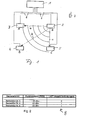
- FIG. 1 shows a multi-cell radio system.
- it has four base stations 2 to 5, preferably via electrical connection lines 6 are connected to a central control unit 1.
- the central control unit 1 essentially controls the transmission and reception operation of the individual base stations 2 to 5 according to a predetermined algorithm, measuring the field strengths, creating a table with a neighborhood list and the transmission of the data to the individual participants.
- the central control unit 1 can be a separate unit be placed in a suitable place.
- the central Control unit 1 in a multi-cell radio system controller integrate that into the telecommunications system anyway is available. This allows, for example, the installation simplify the telecommunications system.
- the base stations 2 to 5 are spatially distributed in one Room or in a site with locations A, B, C and D arranged.
- the base station 2 has in this embodiment the distances to their neighboring base stations 3 to 5 a, b and c respectively. According to the distances a, b and c the base stations receive 3 to 5 different values for radio field strength (RSSI, Receiver Signal Strength Indicator) the sending base station 2.
- RSSI Radio field strength
- the base stations 2 to 5 are, for example, a telecommunications system interconnected and work after one the well-known standards such as the DECT, Bluetooth standard or similar. These standards are known per se and therefore need not be explained in more detail.
- the individual base stations 2 to 5 are preferably so set up that their radio fields at least partially overlap. This ensures that a mobile Terminal 7, for example a radio receiver such as a cell phone, can be a data receiver or similar device, always with one of the base stations 2 to 5 via the radio network communicates if it is in the area in question is stationary or moved in the area.
- a mobile Terminal 7 for example a radio receiver such as a cell phone
- a data receiver or similar device always with one of the base stations 2 to 5 via the radio network communicates if it is in the area in question is stationary or moved in the area.
- both in the mobile Terminal 7 and in base stations 2 to 5 must be one active or passive connection (handover or roaming) when changing a radio cell (base station) to the corresponding one new base station 2 to 5 can be switched.
- the radio field When starting up or when, for example, a new base station to be inserted into the multi-cell radio system, the radio field must be measured again. Furthermore there are the measurement of the radio field when planning a new one Multi-cell radio system Notes on possible sources of error, that would otherwise be difficult to track down.
- the calibration of the radio field controlled by the central control unit 1. For example at system start, i.e. when starting up of the multi-cell radio system first demands the central one Control unit 1 all connected base stations 2 to 5 on looking for their neighboring stations.
- This will be a Base station, in Figure 1, the base station 2, in their Transmission mode switched.
- the base station 2 preferably transmits with their full transmission power. All other base stations, here the base stations 3 to 5 are in one suitable reception mode switched.
- All base stations 3 to 5 that transmit the signals from the Base station 2 received first save this information.
- the se base stations 3 to 5 a corresponding message to the Send central control unit 1 (direct message).
- alternative can also send an indirect message to the central control unit 1 can be sent. That means the received Base stations 3 to 5 send the message to the sending base station 2 and send the answer to the central control unit 1 forwards.
- the transmission and reception operating states differ for the individual radio standards.
- the response message must then be adjusted accordingly.
- the central control unit 1 In the response message to the central control unit 1 preferably the value for the received radio field strength as RSSI value specified with which the sending base station 2 received has been. During later operation, other parameters, such as the load factor, malfunctions or the like be included in the reply message.
- the central control unit 1 After the topology values are recorded for base station 2 the central control unit 1 now switches the next one Base station, for example base station 3 on one Transmission mode and base stations 2, 4 and 5 on reception. This cycle repeats itself until all radio field strengths as well their relevant parameters from all base stations 2 to 5 are recorded.
- the duration of measuring the radio field of a base station can take several seconds depending on the radio standard used lie. The measurement of the entire system can therefore be several Take minutes. Hence the full calibration of the radio field of a multi-cell radio system State of emergency, which only applies to important circumstances such as a system start, in the event of an error or service or changes the operating characteristics of the multi-cell radio system should be done.
- Table 8 is designed as a neighborhood list and contains for example for base station 2 in its first Column the names of base stations 3 to 5. In the second The RSSI values for the radio field strength are entered in the column. A low RSSI value means that the base station is further away than with a larger RSSI value. The RSSI values thus give the relative distances of the individual Base stations 2 to 5, not their absolute locations.
- Load information is entered in the third column correspond to the number of current connections. This Numbers are constantly changing and are controlled by the central control unit 1 correspondingly frequently during operation updated. Of course, other parameters can also be in further columns of table 8 can be saved.
- the table values are preferably based on the radio field strength and / or the load information sorted.
- the sorting is done according to a predetermined algorithm, for example in the Way that the most suitable base station 2 to 5 at the top Job stands. When handover or roaming, you can then use this Base station to be switched first.
- the multi-cell radio system can operate take up. During the operating phase, table 8 if necessary, transmitted to the mobile terminal 7.
- the mobile terminal 7 receives from the central Control unit 1 transmits the finished table 8 and can then according to Table 8 by an intelligent one Switch the selection algorithm to the most suitable base station. It is no longer necessary to measure the radio field yourself.
- the measurement of the radio field can be updated regularly (automatically) at times of low activity or under certain, prevailing conditions. For example when installing an additional base station does not have to re-measure the entire multi-cell radio system become. It is sufficient if the new base station is in transmission mode goes and all other base stations on reception are switched. The prerequisite is that all base stations ready for operation with devices 7 stay.
Landscapes
- Engineering & Computer Science (AREA)
- Computer Networks & Wireless Communication (AREA)
- Signal Processing (AREA)
- Mobile Radio Communication Systems (AREA)
Applications Claiming Priority (2)
| Application Number | Priority Date | Filing Date | Title |
|---|---|---|---|
| DE2001149571 DE10149571A1 (de) | 2001-10-08 | 2001-10-08 | Verfahren zum Einmessen eines Funkfeldes bei einem Mehrzellen-Funksystem sowie Steuereinheit |
| DE10149571 | 2001-10-08 |
Publications (2)
| Publication Number | Publication Date |
|---|---|
| EP1304896A2 true EP1304896A2 (fr) | 2003-04-23 |
| EP1304896A3 EP1304896A3 (fr) | 2003-05-02 |
Family
ID=7701782
Family Applications (1)
| Application Number | Title | Priority Date | Filing Date |
|---|---|---|---|
| EP02022354A Withdrawn EP1304896A3 (fr) | 2001-10-08 | 2002-10-08 | Procédé pour calibrer un champ radio dans un système radio multicellulaire et contrôleur |
Country Status (2)
| Country | Link |
|---|---|
| EP (1) | EP1304896A3 (fr) |
| DE (1) | DE10149571A1 (fr) |
Cited By (3)
| Publication number | Priority date | Publication date | Assignee | Title |
|---|---|---|---|---|
| DE102004010182B3 (de) * | 2004-03-02 | 2005-07-21 | Siemens Ag | Verfahren und Anordnung zum Erfassen einer Funkabdeckung |
| EP1838119A1 (fr) * | 2006-03-22 | 2007-09-26 | Huawei Technologies Co., Ltd. | Procédé de planification et d'optimisation de réseau, réseau radio, station de base et contrôleur de station de base |
| EP2486746B1 (fr) * | 2009-10-09 | 2016-03-16 | Nokia Solutions and Networks Oy | Procédé et appareil permettant de déterminer un intervalle de temps pour un noeud d'accès pour des mesures radio |
Family Cites Families (7)
| Publication number | Priority date | Publication date | Assignee | Title |
|---|---|---|---|---|
| GB2290195B (en) * | 1994-06-10 | 1998-08-05 | Northern Telecom Ltd | Automatic determination and tuning of pico-cell topology for low-power wireless systems |
| JPH08293828A (ja) * | 1995-04-21 | 1996-11-05 | Nec Corp | 携帯無線通信システムにおけるセルサイト試験方式 |
| FI105876B (fi) * | 1997-06-18 | 2000-10-13 | Nokia Networks Oy | Naapurialisolujen määritys tukiasemassa |
| US6122505A (en) * | 1997-12-23 | 2000-09-19 | Telefonaktiebolaget Lm Ericsson | Communication system with base stations having test capabilities |
| DE19916688A1 (de) * | 1999-04-14 | 2000-10-26 | Motorola Inc | Verfahren zum Einbuchen einer Mobilstation in ein zellulares Netz und Mobilstation für ein zellulares Netz |
| SE514264C2 (sv) * | 1999-05-07 | 2001-01-29 | Ericsson Telefon Ab L M | Ett kommunikationssystem |
| US6430414B1 (en) * | 1999-12-29 | 2002-08-06 | Qualcomm Incorporated | Soft handoff algorithm and wireless communication system for third generation CDMA systems |
-
2001
- 2001-10-08 DE DE2001149571 patent/DE10149571A1/de not_active Ceased
-
2002
- 2002-10-08 EP EP02022354A patent/EP1304896A3/fr not_active Withdrawn
Cited By (7)
| Publication number | Priority date | Publication date | Assignee | Title |
|---|---|---|---|---|
| DE102004010182B3 (de) * | 2004-03-02 | 2005-07-21 | Siemens Ag | Verfahren und Anordnung zum Erfassen einer Funkabdeckung |
| WO2005086515A1 (fr) | 2004-03-02 | 2005-09-15 | Siemens Aktiengesellschaft | Procede et dispositif pour detecter une couverture radio |
| US7953403B2 (en) | 2004-03-02 | 2011-05-31 | Siemens Enterprise Communications Gmbh & Co. Kg | Method and arrangement for detecting a radio coverage |
| US8626150B2 (en) | 2004-03-02 | 2014-01-07 | Siemens Enterprise Communications Gmbh & Co. Kg | Method and arrangement for detecting a radio coverage |
| EP1838119A1 (fr) * | 2006-03-22 | 2007-09-26 | Huawei Technologies Co., Ltd. | Procédé de planification et d'optimisation de réseau, réseau radio, station de base et contrôleur de station de base |
| JP2009516947A (ja) * | 2006-03-22 | 2009-04-23 | 華為技術有限公司 | ネットワークの計画及び最適化方法、無線ネットワーク、基地局、及び基地局制御装置 |
| EP2486746B1 (fr) * | 2009-10-09 | 2016-03-16 | Nokia Solutions and Networks Oy | Procédé et appareil permettant de déterminer un intervalle de temps pour un noeud d'accès pour des mesures radio |
Also Published As
| Publication number | Publication date |
|---|---|
| EP1304896A3 (fr) | 2003-05-02 |
| DE10149571A1 (de) | 2003-04-17 |
Similar Documents
| Publication | Publication Date | Title |
|---|---|---|
| DE2702023C2 (de) | Funkkanal-Zuteilungsvorrichtung | |
| DE602004011201T2 (de) | Paketkommunikation zwischen einer sammeleinheit und einer vielzahl von steuervorrichtungen über die stromversorgung | |
| DE69029182T2 (de) | Zuteilungsverfahren von Funksteuerkanälen in Mobil-Kommunikationen | |
| DE3886967T2 (de) | Tragbares schnurloses Kommunikationssystem und Verfahren. | |
| DE60131120T2 (de) | Funkbasisstation, Funkbasisstationsauswahlverfahren, Multicast-Signalübertragungsverfahren und Funkendgerät | |
| EP1238551B1 (fr) | Procede d'affectation de canaux de transmission d'un reseau de telecommunication et poste de reseau | |
| DE10059564A1 (de) | Elektrotechnisches Gerät und Verfahren zur Ortsbestimmung eines solchen Geräts | |
| DE102009052955A1 (de) | Basisstation, Verfahren zum Betreiben einer Basisstation und Kommunikationssystem | |
| DE69822225T2 (de) | System und verfahren zur erfassung der system- und fähigkeitänderungen beim weiterreichen | |
| DE69321205T2 (de) | Anordnung zum Verbindungsaufbau von einem Endgerät zum Netz eines Funkkommunikationssystems mit mehreren Netzen | |
| DE60035083T2 (de) | Unterstützender Konzentrator in einer Umgebung mit mehreren Funkrufkanälen | |
| DE60008979T2 (de) | Verfahren zur Erhaltung einer Kommunikationsverbindung in drahtlosen Netzwerkgruppen | |
| EP1759537B1 (fr) | Procede d'etablissement d'un reseau de communication auto-organise sans fil et transfert de fonctionnalite de station de base | |
| EP0137943B1 (fr) | Réseau radio pour la transmission d'informations entre une paire parmi plusieurs paires de postes radio | |
| DE102008031407A1 (de) | Initialisierungsverfahren und Betriebsverfahren für ein Funknetzwerk | |
| EP1304896A2 (fr) | Procédé pour calibrer un champ radio dans un système radio multicellulaire et contrôleur | |
| EP0806879A2 (fr) | Appareil de teste pour examiner le routage et la taxation dans un réseau de communication mobile et procédé d'utilisation | |
| DE19958556A1 (de) | Mobilfunkgerät eines zellularen Netzwerkes zum Übertragen von Sprache und/oder Daten und Verfahren für ein solches | |
| DE102004062157B4 (de) | Vorrichtung zum Erfassen von Zählerständen | |
| EP1536600B1 (fr) | Méthode de mise en oeuvre d'une voie de communication entre au moins deux dispositifs de communication | |
| DE10045810C2 (de) | Datenübertragungseinrichtung für einen Wagenverbund | |
| EP0883969A1 (fr) | Procede permettant de faire fonctionner des terminaux de telecommunications par l'intermediaire d'au moins deux systemes de communication | |
| DE2634080C3 (de) | Ver fahren zum Weiterschalten einer Funkverbindung | |
| DE60005626T2 (de) | Zweiband-Telefon und Betriebsverfahren | |
| EP1371046B1 (fr) | Procede pour produire des informations de circulation |
Legal Events
| Date | Code | Title | Description |
|---|---|---|---|
| PUAI | Public reference made under article 153(3) epc to a published international application that has entered the european phase |
Free format text: ORIGINAL CODE: 0009012 |
|
| PUAL | Search report despatched |
Free format text: ORIGINAL CODE: 0009013 |
|
| AK | Designated contracting states |
Designated state(s): AT BE BG CH CY CZ DE DK EE ES FI FR GB GR IE IT LI LU MC NL PT SE SK TR |
|
| AX | Request for extension of the european patent |
Extension state: AL LT LV MK RO SI |
|
| AK | Designated contracting states |
Designated state(s): AT BE BG CH CY CZ DE DK EE ES FI FR GB GR IE IT LI LU MC NL PT SE SK TR |
|
| AX | Request for extension of the european patent |
Extension state: AL LT LV MK RO SI |
|
| AKX | Designation fees paid | ||
| REG | Reference to a national code |
Ref country code: DE Ref legal event code: 8566 |
|
| STAA | Information on the status of an ep patent application or granted ep patent |
Free format text: STATUS: THE APPLICATION IS DEEMED TO BE WITHDRAWN |
|
| 18D | Application deemed to be withdrawn |
Effective date: 20031104 |