EP1306064A1 - Instrument destiné à implanter une prothèse intervertébrale - Google Patents
Instrument destiné à implanter une prothèse intervertébrale Download PDFInfo
- Publication number
- EP1306064A1 EP1306064A1 EP01125793A EP01125793A EP1306064A1 EP 1306064 A1 EP1306064 A1 EP 1306064A1 EP 01125793 A EP01125793 A EP 01125793A EP 01125793 A EP01125793 A EP 01125793A EP 1306064 A1 EP1306064 A1 EP 1306064A1
- Authority
- EP
- European Patent Office
- Prior art keywords
- prosthesis
- instrument
- instrument body
- longitudinal direction
- holder
- Prior art date
- Legal status (The legal status is an assumption and is not a legal conclusion. Google has not performed a legal analysis and makes no representation as to the accuracy of the status listed.)
- Withdrawn
Links
Images


Classifications
-
- A—HUMAN NECESSITIES
- A61—MEDICAL OR VETERINARY SCIENCE; HYGIENE
- A61F—FILTERS IMPLANTABLE INTO BLOOD VESSELS; PROSTHESES; DEVICES PROVIDING PATENCY TO, OR PREVENTING COLLAPSING OF, TUBULAR STRUCTURES OF THE BODY, e.g. STENTS; ORTHOPAEDIC, NURSING OR CONTRACEPTIVE DEVICES; FOMENTATION; TREATMENT OR PROTECTION OF EYES OR EARS; BANDAGES, DRESSINGS OR ABSORBENT PADS; FIRST-AID KITS
- A61F2/00—Filters implantable into blood vessels; Prostheses, i.e. artificial substitutes or replacements for parts of the body; Appliances for connecting them with the body; Devices providing patency to, or preventing collapsing of, tubular structures of the body, e.g. stents
- A61F2/02—Prostheses implantable into the body
- A61F2/30—Joints
- A61F2/46—Special tools for implanting artificial joints
- A61F2/4603—Special tools for implanting artificial joints for insertion or extraction of endoprosthetic joints or of accessories thereof
- A61F2/4611—Special tools for implanting artificial joints for insertion or extraction of endoprosthetic joints or of accessories thereof of spinal prostheses
-
- A—HUMAN NECESSITIES
- A61—MEDICAL OR VETERINARY SCIENCE; HYGIENE
- A61B—DIAGNOSIS; SURGERY; IDENTIFICATION
- A61B17/00—Surgical instruments, devices or methods
- A61B17/02—Surgical instruments, devices or methods for holding wounds open, e.g. retractors; Tractors
- A61B17/025—Joint distractors
-
- A—HUMAN NECESSITIES
- A61—MEDICAL OR VETERINARY SCIENCE; HYGIENE
- A61B—DIAGNOSIS; SURGERY; IDENTIFICATION
- A61B17/00—Surgical instruments, devices or methods
- A61B17/00234—Surgical instruments, devices or methods for minimally invasive surgery
- A61B2017/00238—Type of minimally invasive operation
- A61B2017/00261—Discectomy
-
- A—HUMAN NECESSITIES
- A61—MEDICAL OR VETERINARY SCIENCE; HYGIENE
- A61B—DIAGNOSIS; SURGERY; IDENTIFICATION
- A61B17/00—Surgical instruments, devices or methods
- A61B17/02—Surgical instruments, devices or methods for holding wounds open, e.g. retractors; Tractors
- A61B17/025—Joint distractors
- A61B2017/0256—Joint distractors for the spine
-
- A—HUMAN NECESSITIES
- A61—MEDICAL OR VETERINARY SCIENCE; HYGIENE
- A61F—FILTERS IMPLANTABLE INTO BLOOD VESSELS; PROSTHESES; DEVICES PROVIDING PATENCY TO, OR PREVENTING COLLAPSING OF, TUBULAR STRUCTURES OF THE BODY, e.g. STENTS; ORTHOPAEDIC, NURSING OR CONTRACEPTIVE DEVICES; FOMENTATION; TREATMENT OR PROTECTION OF EYES OR EARS; BANDAGES, DRESSINGS OR ABSORBENT PADS; FIRST-AID KITS
- A61F2/00—Filters implantable into blood vessels; Prostheses, i.e. artificial substitutes or replacements for parts of the body; Appliances for connecting them with the body; Devices providing patency to, or preventing collapsing of, tubular structures of the body, e.g. stents
- A61F2/02—Prostheses implantable into the body
- A61F2/30—Joints
- A61F2/46—Special tools for implanting artificial joints
- A61F2/4603—Special tools for implanting artificial joints for insertion or extraction of endoprosthetic joints or of accessories thereof
- A61F2002/4622—Special tools for implanting artificial joints for insertion or extraction of endoprosthetic joints or of accessories thereof having the shape of a forceps or a clamp
-
- A—HUMAN NECESSITIES
- A61—MEDICAL OR VETERINARY SCIENCE; HYGIENE
- A61F—FILTERS IMPLANTABLE INTO BLOOD VESSELS; PROSTHESES; DEVICES PROVIDING PATENCY TO, OR PREVENTING COLLAPSING OF, TUBULAR STRUCTURES OF THE BODY, e.g. STENTS; ORTHOPAEDIC, NURSING OR CONTRACEPTIVE DEVICES; FOMENTATION; TREATMENT OR PROTECTION OF EYES OR EARS; BANDAGES, DRESSINGS OR ABSORBENT PADS; FIRST-AID KITS
- A61F2/00—Filters implantable into blood vessels; Prostheses, i.e. artificial substitutes or replacements for parts of the body; Appliances for connecting them with the body; Devices providing patency to, or preventing collapsing of, tubular structures of the body, e.g. stents
- A61F2/02—Prostheses implantable into the body
- A61F2/30—Joints
- A61F2/46—Special tools for implanting artificial joints
- A61F2/4603—Special tools for implanting artificial joints for insertion or extraction of endoprosthetic joints or of accessories thereof
- A61F2002/4625—Special tools for implanting artificial joints for insertion or extraction of endoprosthetic joints or of accessories thereof with relative movement between parts of the instrument during use
- A61F2002/4627—Special tools for implanting artificial joints for insertion or extraction of endoprosthetic joints or of accessories thereof with relative movement between parts of the instrument during use with linear motion along or rotating motion about the instrument axis or the implantation direction, e.g. telescopic, along a guiding rod, screwing inside the instrument
-
- A—HUMAN NECESSITIES
- A61—MEDICAL OR VETERINARY SCIENCE; HYGIENE
- A61F—FILTERS IMPLANTABLE INTO BLOOD VESSELS; PROSTHESES; DEVICES PROVIDING PATENCY TO, OR PREVENTING COLLAPSING OF, TUBULAR STRUCTURES OF THE BODY, e.g. STENTS; ORTHOPAEDIC, NURSING OR CONTRACEPTIVE DEVICES; FOMENTATION; TREATMENT OR PROTECTION OF EYES OR EARS; BANDAGES, DRESSINGS OR ABSORBENT PADS; FIRST-AID KITS
- A61F2/00—Filters implantable into blood vessels; Prostheses, i.e. artificial substitutes or replacements for parts of the body; Appliances for connecting them with the body; Devices providing patency to, or preventing collapsing of, tubular structures of the body, e.g. stents
- A61F2/02—Prostheses implantable into the body
- A61F2/30—Joints
- A61F2/46—Special tools for implanting artificial joints
- A61F2/4603—Special tools for implanting artificial joints for insertion or extraction of endoprosthetic joints or of accessories thereof
- A61F2002/4625—Special tools for implanting artificial joints for insertion or extraction of endoprosthetic joints or of accessories thereof with relative movement between parts of the instrument during use
- A61F2002/4628—Special tools for implanting artificial joints for insertion or extraction of endoprosthetic joints or of accessories thereof with relative movement between parts of the instrument during use with linear motion along or rotating motion about an axis transverse to the instrument axis or to the implantation direction, e.g. clamping
-
- A—HUMAN NECESSITIES
- A61—MEDICAL OR VETERINARY SCIENCE; HYGIENE
- A61F—FILTERS IMPLANTABLE INTO BLOOD VESSELS; PROSTHESES; DEVICES PROVIDING PATENCY TO, OR PREVENTING COLLAPSING OF, TUBULAR STRUCTURES OF THE BODY, e.g. STENTS; ORTHOPAEDIC, NURSING OR CONTRACEPTIVE DEVICES; FOMENTATION; TREATMENT OR PROTECTION OF EYES OR EARS; BANDAGES, DRESSINGS OR ABSORBENT PADS; FIRST-AID KITS
- A61F2/00—Filters implantable into blood vessels; Prostheses, i.e. artificial substitutes or replacements for parts of the body; Appliances for connecting them with the body; Devices providing patency to, or preventing collapsing of, tubular structures of the body, e.g. stents
- A61F2/02—Prostheses implantable into the body
- A61F2/30—Joints
- A61F2/46—Special tools for implanting artificial joints
- A61F2002/4681—Special tools for implanting artificial joints by applying mechanical shocks, e.g. by hammering
Definitions
- intervertebral prostheses each consisting of two with one Vertebral body to be connected prosthesis plates and one arranged in between Insertion instruments are known (EP-A-333 990), which have two prosthesis holders at their front end, which each hold a prosthetic plate.
- the prosthesis holders are connected by a parallel guide, which allows the Prosthesis plates first closely approximate each other to make them easier in to be able to introduce the narrow intervertebral space, and then (with the adjacent vertebrae) to spread apart to the prosthesis core to be able to insert. Then the prosthesis holders are brought closer together again so that the prosthesis plates keep the prosthesis core in its functional position include and the instrument is removed.
- the known The instrument is designed as pliers that are opposite the direction of the prosthesis holders, that match the median direction of the body should be angled to prevent the insertion of the prosthesis core to be.
- This has several disadvantages.
- the force for Do not insert the prosthesis parts in the intervertebral space in the longitudinal direction of the instrument. Rather, it is something special Approach instrument required.
- An instrument for inserting such a prosthesis is also known (DE-U-299 16 078) by a lower pair of guide rods and an upper guide rod which is formed at the rear end are articulated and prosthesis holders at their front ends wear. They form a guideway for an expansion element. If this is propelled between them by means of a rack, spreads it pulls the rod ends apart and at the same time pushes the prosthesis core in front of him until he has reached the desired end position. Then the expansion element is withdrawn to the prosthesis plates Approaching the prosthesis core. The spreading movement is with the introduction of the prosthesis core inevitably coupled, so that the spreading process does not separately monitored and difficult to observe.
- the invention seeks to provide an instrument that introduces one of the of the prosthesis core allows independent expansion of the prosthesis plates and its longitudinal direction when inserting the prostheses with the median direction of the body matches.
- It relates to an instrument for inserting an intervertebral prosthesis, the two, which can be spread apart and are connected by a parallel guide
- Has prosthesis holders for a pair of prosthesis plates The first of these prosthesis holders is fixed to an elongated body of the instrument arranged in accordance with its longitudinal direction.
- the second prosthesis holder is by means of the parallel guide on the instrument body held.
- a semi-trailing arm is provided, the first end on the instrument body movable in the longitudinal direction is articulated. Its second end is on the second prosthesis holder articulated. Its first end is in the longitudinal direction of the Instrument body movable actuator connected.
- the semi-trailing arm can be part of a parallel scissor guide.
- the semi-trailing arm is symmetrical in pairs on both sides of the instrument body provided an asymmetrical and tending to tilt Avoid power transmission.
- the width at least the transverse dimensions of the between the Prosthesis core to be inserted and a prosthesis core provided therefor Corresponds to the prosthesis core holder.
- the prosthesis core can rely on this Easily through the instrument and through both sides Limbs are brought in guided. So that the surgeon when inserting of the prosthesis core slightly that position of the prosthesis core holder finds in which of the prosthesis core the desired position between has reached the prosthesis plates are the insertion instrument and the prosthesis core holder expediently with interacting stops provided that determine this end position.
- the actuating device expediently comprises a handle and a translation facility.
- the translation device can, for example be formed by a threaded spindle. It has more convenience have proven to be designed as a handle lever, which is connected to a shorter working lever, the translation device forms. It is conveniently arranged so that it at the same time the lateral movement of the handle lever converts to the in Operating direction running in the longitudinal direction of the instrument body.
- the semi-trailing arm can with its first end on one on the instrument body be articulated in its longitudinal direction. Instead of of which it is also possible that it is a member of a pair of toggle levers, the actuator directly or indirectly at the knee point of the Lever pairs attacks.
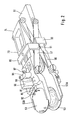
- the prosthesis holders 52 are fork-shaped and open at the end. Your side legs form guides for the edge of the prosthesis plates 53. They allow the prosthesis plates overcoming a frictional force in the longitudinal direction of the instrument in the Insert prosthesis holders 52 or let them slide out.
- the end of the prosthesis body 51 has a striking plate 54 Impacts on this plate can cause the prosthesis plates 53 to be held by the Prosthesis holders 52 are driven between two vertebral bodies.
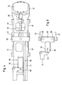
- the lower prosthesis holder 52A (Figs. 9 and 10) is with the instrument body 51 fixed and even connected in one piece in the example shown.
- the upper prosthesis holder 52B is by means of a scissor assembly, which consists of scissor members 56, 57 with the instrument body 51 connected.
- the scissor assembly 56, 57 is designed so that the upper Prosthesis holder 52B is only perpendicular to the lower prosthesis holder 52A and can move parallel to it.
- the prosthesis holders can be largely approximated to each other (Fig. 1) to make it easier to be driven into the intervertebral space. You can together be spread apart with the neighboring vertebral bodies (Figs. 2 and 3) to give space for the insertion of the prosthesis core 77 between the prosthesis plates 53. Then they are brought closer together again, to hold the prosthesis core in the desired position. The instrument can then be removed.
- the rear bolts 58, 59 of the scissor members 56, 57 slide in elongated holes of the instrument body 51 or the plate 73, which is the upper prosthesis holder 52B continues to the rear.
- the direction of the elongated holes corresponds to the longitudinal direction of the instrument.
- the front bolts 60 the scissor members 56, 57 are rigidly connected to the prosthesis holders 52.
- To spread the prosthesis holders is a device provided the rear bolt 58 of the scissor member 57 in the longitudinal direction of the instrument moves.
- the handle lever 61 is provided for this, which is pivotable on the instrument body about an axis 62 and a working lever 63, which on the rear end of a sliding block 64 acts, which is part of a T-shaped carriage 65 (Fig.
- the working lever 63, the slide 65 and the trailing arms 57 thus form an arrangement for adjusting the Distance of the prosthesis holders 52. It is understood that this arrangement can also be replaced by other versions. Also recognizes one that the spreading force is not necessarily over parts of the scissor assembly needs to be exercised.
- a separate link can be provided for the spread.
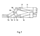
- This alternative is illustrated in Fig. 7.
- the plate 73 on its front End carries the upper prosthesis holder 52 is - as in that previously described Exemplary embodiment - by means of a scissor arrangement 56,57 carried by the instrument body 51. Deviating from that version the spreader is implemented independently of the scissor arrangement.
- the links 100, 101 form a toggle lever arrangement. An end this handlebar is connected to the instrument body 51 or the plate 73. Its other end forms the knee 103, at which the end of a handlebar 102 engages, the other end 104 with the actuator connected is.
- connection can be made as shown in Fig. 6 is shown.
- the one independent of the scissors arrangement 56.57 Spreading arrangement has the advantage that the angle at which the handlebars 100,101 and 102 are claimed, regardless of a parallel guidance function only with a view to cheap power transmission can be measured.
- the hand lever 61 is through a threaded spindle 71 with a toggle nut 72 supplements, which facilitates the process and allows the instrument temporarily set in the spread position.
- a device for ejecting the prosthesis plates 53 will now be made the prosthesis holders 52 or for pressing the instrument off the Prosthesis holders or the adjacent vertebrae described.
- the prosthetic guides 52 contained behind the receiving space for the prosthetic plates 53 a guide groove 80 which is in the longitudinal direction of the instrument and thus runs in the sliding direction of the prosthesis holders 52. It contains a slider 81, the front end 82 at the edge of the in the prosthesis holder located prosthesis plate and therefore as Prosthesis stop is called.
- the rear, in Fig. 2 and 3 not visible end of the slide 81 is also in the longitudinal direction of the instrument guided rod 83 rigidly connected.
- the rear end of the rod 83 mounted in the instrument body 51 is on, as shown in FIG.
- the stop element 84 is in turn rigidly connected to a push rod 86, which is mounted in the instrument body 51 so as to be longitudinally displaceable and into one Handle 87 leads.
- a push rod 86 which is mounted in the instrument body 51 so as to be longitudinally displaceable and into one Handle 87 leads.
- the movement of the handle 87 only affects the slide 81 made in the lower part of the instrument, namely in the instrument body, is arranged. So that the slide 81 of both prosthesis holders move synchronously, a movement transmission device is provided.
- the rod controlling the slide 81 of the upper prosthesis holder 83 is firmly connected at its rear end to a stop element 85, this as well as the stop element 84 of the lower prosthesis holder is movably guided in the longitudinal direction of the instrument.
- the lower stop element 84 has on both sides towering stop legs 90 behind and adjacent legs 91 that are from the upper stop member 85 protrude on both sides.
- the neighboring ones also lie End faces of the stop legs 90, 91 to each other. If through now Actuation of the handle 87, the lower stop element 84 with the stop legs 90 is pushed forward by their interaction with the stop legs 91 of the upper stop element also the Slide slide 81 of the upper prosthesis holder forward. The two Slider 81 thus move synchronously. Because the interacting Stop surfaces 90, 91 run perpendicular to the instrument's longitudinal direction, the synchronous movement of the slider 81 is independent of the respective one Distance between the prosthesis holders guaranteed.
- Each slide 81 carries a projection 95 rigidly connected to it and a in the longitudinal direction of the slide on this led block 96, the with its end face forms the vertebral stop. If the prosthesis holders with the prosthesis plates 53 located in the space two vertebrae are driven, the end faces of the Finally, vertebral stops 96 on the ventral edges of the vertebral bodies on. By the distance of the end faces of the vertebral stops 96 from the The depth at which the prosthesis plates are determined is thus determined get into the intervertebral space. By adjusting the vertebral stops 96 on the slides 81 this depth can be changed.
Landscapes
- Health & Medical Sciences (AREA)
- Engineering & Computer Science (AREA)
- Biomedical Technology (AREA)
- Life Sciences & Earth Sciences (AREA)
- Animal Behavior & Ethology (AREA)
- Surgery (AREA)
- Orthopedic Medicine & Surgery (AREA)
- Transplantation (AREA)
- Veterinary Medicine (AREA)
- Public Health (AREA)
- Heart & Thoracic Surgery (AREA)
- General Health & Medical Sciences (AREA)
- Physical Education & Sports Medicine (AREA)
- Vascular Medicine (AREA)
- Oral & Maxillofacial Surgery (AREA)
- Cardiology (AREA)
- Nuclear Medicine, Radiotherapy & Molecular Imaging (AREA)
- Neurology (AREA)
- Medical Informatics (AREA)
- Molecular Biology (AREA)
- Prostheses (AREA)
Priority Applications (5)
| Application Number | Priority Date | Filing Date | Title |
|---|---|---|---|
| EP01125793A EP1306064A1 (fr) | 2001-10-29 | 2001-10-29 | Instrument destiné à implanter une prothèse intervertébrale |
| DE2002125703 DE10225703A1 (de) | 2001-10-29 | 2002-06-10 | Instrumentarium zum Einsetzen einer Zwischenwirbelprothese |
| PCT/EP2002/012025 WO2003037230A2 (fr) | 2001-10-29 | 2002-10-28 | Instrument permettant d'implanter une prothese intervertebrale |
| ARP020104089 AR037055A1 (es) | 2001-10-29 | 2002-10-28 | Instrumental para colocar una protesis intervertebral |
| US10/493,888 US7963971B2 (en) | 2001-10-29 | 2002-10-28 | Instrumentation for insertion of an inter-vertebral prosthesis |
Applications Claiming Priority (1)
| Application Number | Priority Date | Filing Date | Title |
|---|---|---|---|
| EP01125793A EP1306064A1 (fr) | 2001-10-29 | 2001-10-29 | Instrument destiné à implanter une prothèse intervertébrale |
Publications (1)
| Publication Number | Publication Date |
|---|---|
| EP1306064A1 true EP1306064A1 (fr) | 2003-05-02 |
Family
ID=8179109
Family Applications (1)
| Application Number | Title | Priority Date | Filing Date |
|---|---|---|---|
| EP01125793A Withdrawn EP1306064A1 (fr) | 2001-10-29 | 2001-10-29 | Instrument destiné à implanter une prothèse intervertébrale |
Country Status (3)
| Country | Link |
|---|---|
| EP (1) | EP1306064A1 (fr) |
| AR (1) | AR037055A1 (fr) |
| DE (1) | DE10225703A1 (fr) |
Cited By (23)
| Publication number | Priority date | Publication date | Assignee | Title |
|---|---|---|---|---|
| WO2007053364A1 (fr) * | 2005-10-31 | 2007-05-10 | Depuy Spine, Inc. | Dispositif de revision d'arthroplastie et procede associe |
| EP1482877B1 (fr) * | 2002-03-11 | 2007-05-30 | Spinal Concepts Inc. | Equipement pour l'installation d'implants vertebraux |
| WO2007121320A2 (fr) | 2006-04-12 | 2007-10-25 | Spinalmotion, Inc. | Dispositif vertébral postérieur et procédé associé |
| US7320689B2 (en) | 2003-07-15 | 2008-01-22 | Cervitech, Inc. | Multi-part cervical endoprosthesis with insertion instrument |
| WO2008014453A2 (fr) | 2006-07-28 | 2008-01-31 | Spinalmotion, Inc. | Prothèse vertébrale munie de plusieurs piliers d'ancrage |
| US7442211B2 (en) | 2003-05-27 | 2008-10-28 | Spinalmotion, Inc. | Intervertebral prosthetic disc |
| US7531001B2 (en) | 2002-09-19 | 2009-05-12 | Spinalmotion, Inc. | Intervertebral prosthesis |
| US7569067B2 (en) | 2003-07-15 | 2009-08-04 | Cervitech, Inc. | Insertion instrument for cervical prostheses |
| US7575599B2 (en) | 2004-07-30 | 2009-08-18 | Spinalmotion, Inc. | Intervertebral prosthetic disc with metallic core |
| US7585326B2 (en) | 2004-08-06 | 2009-09-08 | Spinalmotion, Inc. | Methods and apparatus for intervertebral disc prosthesis insertion |
| US7637913B2 (en) | 2003-01-31 | 2009-12-29 | Spinalmotion, Inc. | Spinal midline indicator |
| US8083797B2 (en) | 2005-02-04 | 2011-12-27 | Spinalmotion, Inc. | Intervertebral prosthetic disc with shock absorption |
| US8206449B2 (en) | 2008-07-17 | 2012-06-26 | Spinalmotion, Inc. | Artificial intervertebral disc placement system |
| US8506631B2 (en) | 2007-08-09 | 2013-08-13 | Spinalmotion, Inc. | Customized intervertebral prosthetic disc with shock absorption |
| US8685035B2 (en) | 2003-01-31 | 2014-04-01 | Spinalmotion, Inc. | Intervertebral prosthesis placement instrument |
| US8758441B2 (en) | 2007-10-22 | 2014-06-24 | Spinalmotion, Inc. | Vertebral body replacement and method for spanning a space formed upon removal of a vertebral body |
| US8764833B2 (en) | 2008-03-11 | 2014-07-01 | Spinalmotion, Inc. | Artificial intervertebral disc with lower height |
| US8845730B2 (en) | 2008-07-18 | 2014-09-30 | Simplify Medical, Inc. | Posterior prosthetic intervertebral disc |
| US9011544B2 (en) | 2008-05-05 | 2015-04-21 | Simplify Medical, Inc. | Polyaryletherketone artificial intervertebral disc |
| US9034038B2 (en) | 2008-04-11 | 2015-05-19 | Spinalmotion, Inc. | Motion limiting insert for an artificial intervertebral disc |
| US9220603B2 (en) | 2008-07-02 | 2015-12-29 | Simplify Medical, Inc. | Limited motion prosthetic intervertebral disc |
| US9655741B2 (en) | 2003-05-27 | 2017-05-23 | Simplify Medical Pty Ltd | Prosthetic disc for intervertebral insertion |
| US11266449B2 (en) | 2017-12-19 | 2022-03-08 | Orthopediatrics Corp | Osteotomy device and methods |
Families Citing this family (1)
| Publication number | Priority date | Publication date | Assignee | Title |
|---|---|---|---|---|
| US7294134B2 (en) | 2004-07-28 | 2007-11-13 | Weber Instrumente Gmbh | Surgical instrument for the introduction of a multi-component intervertebral prosthesis |
Citations (5)
| Publication number | Priority date | Publication date | Assignee | Title |
|---|---|---|---|---|
| EP0333990A2 (fr) * | 1988-03-23 | 1989-09-27 | Waldemar Link (GmbH & Co.) | Jeu d'instruments chirurgical |
| DE29916078U1 (de) * | 1999-09-14 | 1999-11-25 | Aesculap Ag & Co Kg | Einsetzinstrument für ein Zwischenwirbelimplantat |
| DE19836498A1 (de) * | 1998-08-12 | 2000-02-17 | Medinorm Ag | Spreizvorrichtung |
| DE20004812U1 (de) * | 2000-03-16 | 2000-09-28 | Knop, Christian, Dr., 30163 Hannover | Endoskopische Spreizzange |
| DE20116410U1 (de) * | 2001-09-26 | 2001-11-29 | Aesculap AG & Co. KG, 78532 Tuttlingen | Chirurgisches Instrument |
-
2001
- 2001-10-29 EP EP01125793A patent/EP1306064A1/fr not_active Withdrawn
-
2002
- 2002-06-10 DE DE2002125703 patent/DE10225703A1/de not_active Withdrawn
- 2002-10-28 AR ARP020104089 patent/AR037055A1/es not_active Application Discontinuation
Patent Citations (5)
| Publication number | Priority date | Publication date | Assignee | Title |
|---|---|---|---|---|
| EP0333990A2 (fr) * | 1988-03-23 | 1989-09-27 | Waldemar Link (GmbH & Co.) | Jeu d'instruments chirurgical |
| DE19836498A1 (de) * | 1998-08-12 | 2000-02-17 | Medinorm Ag | Spreizvorrichtung |
| DE29916078U1 (de) * | 1999-09-14 | 1999-11-25 | Aesculap Ag & Co Kg | Einsetzinstrument für ein Zwischenwirbelimplantat |
| DE20004812U1 (de) * | 2000-03-16 | 2000-09-28 | Knop, Christian, Dr., 30163 Hannover | Endoskopische Spreizzange |
| DE20116410U1 (de) * | 2001-09-26 | 2001-11-29 | Aesculap AG & Co. KG, 78532 Tuttlingen | Chirurgisches Instrument |
Cited By (93)
| Publication number | Priority date | Publication date | Assignee | Title |
|---|---|---|---|---|
| US7637952B2 (en) * | 2002-03-11 | 2009-12-29 | Zimmer Spine, Inc. | Instrumentation and procedure for implanting spinal implant devices |
| EP1482877B1 (fr) * | 2002-03-11 | 2007-05-30 | Spinal Concepts Inc. | Equipement pour l'installation d'implants vertebraux |
| US10517738B2 (en) | 2002-09-19 | 2019-12-31 | Simplify Medical Pty Ltd | Intervertebral prothesis |
| US10413420B2 (en) | 2002-09-19 | 2019-09-17 | Simplify Medical Pty Ltd | Intervertebral prosthesis |
| US8262732B2 (en) | 2002-09-19 | 2012-09-11 | Spinalmotion, Inc. | Intervertebral prosthesis |
| US9839525B2 (en) | 2002-09-19 | 2017-12-12 | Simplify Medical Pty Ltd | Intervertebral prosthesis |
| US7531001B2 (en) | 2002-09-19 | 2009-05-12 | Spinalmotion, Inc. | Intervertebral prosthesis |
| US10166113B2 (en) | 2002-09-19 | 2019-01-01 | Simplify Medical Pty Ltd | Intervertebral prosthesis |
| US11707360B2 (en) | 2002-09-19 | 2023-07-25 | Simplify Medical Pty Ltd | Intervertebral prosthesis |
| US11285013B2 (en) | 2002-09-19 | 2022-03-29 | Simplify Medical Pty Ltd | Intervertebral prosthesis |
| US11344427B2 (en) | 2002-09-19 | 2022-05-31 | Simplify Medical Pty Ltd | Intervertebral prosthesis |
| US7731754B2 (en) | 2002-09-19 | 2010-06-08 | Spinalmotion, Inc. | Intervertebral prosthesis |
| US8090428B2 (en) | 2003-01-31 | 2012-01-03 | Spinalmotion, Inc. | Spinal midline indicator |
| US10105131B2 (en) | 2003-01-31 | 2018-10-23 | Simplify Medical Pty Ltd | Intervertebral prosthesis placement instrument |
| US8685035B2 (en) | 2003-01-31 | 2014-04-01 | Spinalmotion, Inc. | Intervertebral prosthesis placement instrument |
| US9402745B2 (en) | 2003-01-31 | 2016-08-02 | Simplify Medical, Inc. | Intervertebral prosthesis placement instrument |
| US7637913B2 (en) | 2003-01-31 | 2009-12-29 | Spinalmotion, Inc. | Spinal midline indicator |
| US10342671B2 (en) | 2003-05-27 | 2019-07-09 | Simplify Medical Pty Ltd | Intervertebral prosthetic disc |
| USRE46802E1 (en) | 2003-05-27 | 2018-04-24 | Simplify Medical Pty Limited | Intervertebral prosthetic disc with metallic core |
| US11376130B2 (en) | 2003-05-27 | 2022-07-05 | Simplify Medical Pty Ltd | Intervertebral prosthetic disc |
| US9107762B2 (en) | 2003-05-27 | 2015-08-18 | Spinalmotion, Inc. | Intervertebral prosthetic disc with metallic core |
| US8092538B2 (en) | 2003-05-27 | 2012-01-10 | Spinalmotion, Inc. | Intervertebral prosthetic disc |
| US9439774B2 (en) | 2003-05-27 | 2016-09-13 | Simplify Medical Pty Ltd | Intervertebral prosthetic disc |
| EP2226038A1 (fr) | 2003-05-27 | 2010-09-08 | Spinalmotion, Inc. | Prothèse de disque pour insertion intervertébrale |
| US9655741B2 (en) | 2003-05-27 | 2017-05-23 | Simplify Medical Pty Ltd | Prosthetic disc for intervertebral insertion |
| US10357376B2 (en) | 2003-05-27 | 2019-07-23 | Simplify Medical Pty Ltd | Intervertebral prosthetic disc |
| US8444695B2 (en) | 2003-05-27 | 2013-05-21 | Spinalmotion, Inc. | Prosthetic disc for intervertebral insertion |
| EP2161008A2 (fr) | 2003-05-27 | 2010-03-10 | Spinalmotion, Inc. | Prothèse de disque pour insertion intervertébrale |
| US10342670B2 (en) | 2003-05-27 | 2019-07-09 | Simplify Medical Pty Ltd | Intervertebral prosthetic disc |
| US8454698B2 (en) | 2003-05-27 | 2013-06-04 | Spinalmotion, Inc. | Prosthetic disc for intervertebral insertion |
| US10219911B2 (en) | 2003-05-27 | 2019-03-05 | Simplify Medical Pty Ltd | Prosthetic disc for intervertebral insertion |
| US7753956B2 (en) | 2003-05-27 | 2010-07-13 | Spinalmotion, Inc. | Prosthetic disc for intervertebral insertion |
| US8974533B2 (en) | 2003-05-27 | 2015-03-10 | Simplify Medical, Inc. | Prosthetic disc for intervertebral insertion |
| US11771565B2 (en) | 2003-05-27 | 2023-10-03 | Simplify Medical Pty Ltd | Prosthetic disc for intervertebral insertion |
| US10052211B2 (en) | 2003-05-27 | 2018-08-21 | Simplify Medical Pty Ltd. | Prosthetic disc for intervertebral insertion |
| US8771356B2 (en) | 2003-05-27 | 2014-07-08 | Spinalmotion, Inc. | Intervertebral prosthetic disc |
| US9788965B2 (en) | 2003-05-27 | 2017-10-17 | Simplify Medical Pty Ltd | Prosthetic disc for intervertebral insertion |
| US8845729B2 (en) | 2003-05-27 | 2014-09-30 | Simplify Medical, Inc. | Prosthetic disc for intervertebral insertion |
| US7442211B2 (en) | 2003-05-27 | 2008-10-28 | Spinalmotion, Inc. | Intervertebral prosthetic disc |
| US7569067B2 (en) | 2003-07-15 | 2009-08-04 | Cervitech, Inc. | Insertion instrument for cervical prostheses |
| US7320689B2 (en) | 2003-07-15 | 2008-01-22 | Cervitech, Inc. | Multi-part cervical endoprosthesis with insertion instrument |
| US8062371B2 (en) | 2004-07-30 | 2011-11-22 | Spinalmotion, Inc. | Intervertebral prosthetic disc with metallic core |
| US7575599B2 (en) | 2004-07-30 | 2009-08-18 | Spinalmotion, Inc. | Intervertebral prosthetic disc with metallic core |
| US8002834B2 (en) | 2004-07-30 | 2011-08-23 | Spinalmotion, Inc. | Intervertebral prosthetic disc with metallic core |
| US8206447B2 (en) | 2004-08-06 | 2012-06-26 | Spinalmotion, Inc. | Methods and apparatus for intervertebral disc prosthesis insertion |
| US8974531B2 (en) | 2004-08-06 | 2015-03-10 | Simplify Medical, Inc. | Methods and apparatus for intervertebral disc prosthesis insertion |
| US10085853B2 (en) | 2004-08-06 | 2018-10-02 | Simplify Medical Pty Ltd | Methods and apparatus for intervertebral disc prosthesis insertion |
| US7585326B2 (en) | 2004-08-06 | 2009-09-08 | Spinalmotion, Inc. | Methods and apparatus for intervertebral disc prosthesis insertion |
| US9956091B2 (en) | 2004-08-06 | 2018-05-01 | Simplify Medical Pty Ltd | Methods and apparatus for intervertebral disc prosthesis insertion |
| US11857438B2 (en) | 2004-08-06 | 2024-01-02 | Simplify Medical Pty Ltd | Methods and apparatus for intervertebral disc prosthesis insertion |
| US9839532B2 (en) | 2004-08-06 | 2017-12-12 | Simplify Medical Pty Ltd | Methods and apparatus for intervertebral disc prosthesis insertion |
| US10888437B2 (en) | 2004-08-06 | 2021-01-12 | Simplify Medical Pty Ltd | Methods and apparatus for intervertebral disc prosthesis insertion |
| EP3241529A1 (fr) | 2004-08-06 | 2017-11-08 | Simplify Medical, Inc. | Procédés et appareil permettant d'insérer une prothèse de disque intervertébral |
| US10130494B2 (en) | 2004-08-06 | 2018-11-20 | Simplify Medical Pty Ltd. | Methods and apparatus for intervertebral disc prosthesis insertion |
| US8083797B2 (en) | 2005-02-04 | 2011-12-27 | Spinalmotion, Inc. | Intervertebral prosthetic disc with shock absorption |
| US8398712B2 (en) | 2005-02-04 | 2013-03-19 | Spinalmotion, Inc. | Intervertebral prosthetic disc with shock absorption |
| WO2007053364A1 (fr) * | 2005-10-31 | 2007-05-10 | Depuy Spine, Inc. | Dispositif de revision d'arthroplastie et procede associe |
| US7867237B2 (en) | 2005-10-31 | 2011-01-11 | Depuy Spine, Inc. | Arthroplasty revision device and method |
| USRE47796E1 (en) | 2006-04-12 | 2020-01-07 | Simplify Medical Pty Ltd | Posterior spinal device and method |
| US8801792B2 (en) | 2006-04-12 | 2014-08-12 | Spinalmotion, Inc. | Posterio spinal device and method |
| US8486147B2 (en) | 2006-04-12 | 2013-07-16 | Spinalmotion, Inc. | Posterior spinal device and method |
| WO2007121320A2 (fr) | 2006-04-12 | 2007-10-25 | Spinalmotion, Inc. | Dispositif vertébral postérieur et procédé associé |
| US8734519B2 (en) | 2006-04-12 | 2014-05-27 | Spinalmotion, Inc. | Posterior spinal device and method |
| WO2008014453A2 (fr) | 2006-07-28 | 2008-01-31 | Spinalmotion, Inc. | Prothèse vertébrale munie de plusieurs piliers d'ancrage |
| US9827108B2 (en) | 2007-08-09 | 2017-11-28 | Simplify Medical Pty Ltd | Customized intervertebral prosthetic disc with shock absorption |
| US9687355B2 (en) | 2007-08-09 | 2017-06-27 | Simplify Medical Pty Ltd | Customized intervertebral prosthetic disc with shock absorption |
| US8506631B2 (en) | 2007-08-09 | 2013-08-13 | Spinalmotion, Inc. | Customized intervertebral prosthetic disc with shock absorption |
| US9554917B2 (en) | 2007-08-09 | 2017-01-31 | Simplify Medical Pty Ltd | Customized intervertebral prosthetic disc with shock absorption |
| US12029656B2 (en) | 2007-08-09 | 2024-07-09 | Globus Medical Inc. | Customized intervertebral prosthetic disc with shock absorption |
| US11229526B2 (en) | 2007-08-09 | 2022-01-25 | Simplify Medical Pty Ltd. | Customized intervertebral prosthetic disc with shock absorption |
| US10548739B2 (en) | 2007-08-09 | 2020-02-04 | Simplify Medical Pty Ltd | Customized intervertebral prosthetic disc with shock absorption |
| US11364129B2 (en) | 2007-10-22 | 2022-06-21 | Simplify Medical Pty Ltd | Method and spacer device for spanning a space formed upon removal of an intervertebral disc |
| USRE47470E1 (en) | 2007-10-22 | 2019-07-02 | Simplify Medical Pty Ltd | Vertebral body placement and method for spanning a space formed upon removal of a vertebral body |
| US8758441B2 (en) | 2007-10-22 | 2014-06-24 | Spinalmotion, Inc. | Vertebral body replacement and method for spanning a space formed upon removal of a vertebral body |
| US9883945B2 (en) | 2008-03-11 | 2018-02-06 | Simplify Medical Pty Ltd | Artificial intervertebral disc with lower height |
| US12138171B2 (en) | 2008-03-11 | 2024-11-12 | Simplify Medical Pty Ltd. | Artificial intervertebral disc with lower height |
| US9668878B2 (en) | 2008-03-11 | 2017-06-06 | Simplify Medical Pty Ltd | Artificial intervertebral disc with lower height |
| US10517733B2 (en) | 2008-03-11 | 2019-12-31 | Simplify Medical Pty Ltd | Artificial intervertebral disc with lower height |
| US8764833B2 (en) | 2008-03-11 | 2014-07-01 | Spinalmotion, Inc. | Artificial intervertebral disc with lower height |
| US11357633B2 (en) | 2008-03-11 | 2022-06-14 | Simplify Medical Pty Ltd | Artificial intervertebral disc with lower height |
| US9439775B2 (en) | 2008-03-11 | 2016-09-13 | Simplify Medical Pty Ltd | Artificial intervertebral disc with lower height |
| US9034038B2 (en) | 2008-04-11 | 2015-05-19 | Spinalmotion, Inc. | Motion limiting insert for an artificial intervertebral disc |
| US11207190B2 (en) | 2008-05-05 | 2021-12-28 | Simplify Medical Pty Ltd | Polyaryletherketone artificial intervertebral disc |
| US9011544B2 (en) | 2008-05-05 | 2015-04-21 | Simplify Medical, Inc. | Polyaryletherketone artificial intervertebral disc |
| US9220603B2 (en) | 2008-07-02 | 2015-12-29 | Simplify Medical, Inc. | Limited motion prosthetic intervertebral disc |
| US8206449B2 (en) | 2008-07-17 | 2012-06-26 | Spinalmotion, Inc. | Artificial intervertebral disc placement system |
| US8636805B2 (en) | 2008-07-17 | 2014-01-28 | Spinalmotion, Inc. | Artificial intervertebral disc placement system |
| US8845730B2 (en) | 2008-07-18 | 2014-09-30 | Simplify Medical, Inc. | Posterior prosthetic intervertebral disc |
| US11413156B2 (en) | 2008-07-18 | 2022-08-16 | Simplify Medical Pty Ltd. | Posterior prosthetic intervertebral disc |
| US11324605B2 (en) | 2008-07-18 | 2022-05-10 | Simplify Medical Pty Ltd | Posterior prosthetic intervertebral disc |
| US11986395B2 (en) | 2008-07-18 | 2024-05-21 | Simplify Medical Pty Ltd | Posterior prosthetic intervertebral disc |
| US9351846B2 (en) | 2008-07-18 | 2016-05-31 | Simplify Medical, Inc. | Posterior prosthetic intervertebral disc |
| US11266449B2 (en) | 2017-12-19 | 2022-03-08 | Orthopediatrics Corp | Osteotomy device and methods |
Also Published As
| Publication number | Publication date |
|---|---|
| DE10225703A1 (de) | 2003-05-08 |
| AR037055A1 (es) | 2004-10-20 |
Similar Documents
| Publication | Publication Date | Title |
|---|---|---|
| EP1306064A1 (fr) | Instrument destiné à implanter une prothèse intervertébrale | |
| EP1222903B1 (fr) | Instrument chirurgical pour implanter une prothèse intervertébrale | |
| WO2003037230A2 (fr) | Instrument permettant d'implanter une prothese intervertebrale | |
| EP2056727B1 (fr) | Pince chirurgicale | |
| EP1996091B1 (fr) | Instrument chirurgical | |
| DE10102089C1 (de) | Chirurgisches Instrument | |
| EP0782412B1 (fr) | Instrument de chirurgie | |
| DE20012549U1 (de) | Einsetzinstrument für ein Zwischenwirbelimplantat | |
| EP0117894A2 (fr) | Endoscope avec instrument médical avec dispositif de préhension | |
| EP2702951B1 (fr) | Instrument médical, en particulier chirurgical, à tige coulissante | |
| DE4015562A1 (de) | Zange zum anlegen von blutstillenden clips | |
| EP0513471A2 (fr) | Instrument chirurgical | |
| DE29713150U1 (de) | Chirurgisches Instrument | |
| WO2007144172A1 (fr) | Pince à séquestre chirurgicale | |
| DE10060769C2 (de) | Medizinisches Instrument | |
| DE20103630U1 (de) | Chirurgisches Instrument | |
| EP0540721A1 (fr) | Appareil chirurgical | |
| DE102014207900A1 (de) | Maulteil für ein chirurgisches Rohrschaft-Instrument | |
| EP1699368B1 (fr) | Instrument medical de coupe et/ou de retenue | |
| DE4309569C1 (de) | Griff für ein chirurgisches Rohrschaftinstrument | |
| DE102004041515A1 (de) | Medizinische Zange | |
| DE19747043A1 (de) | Endoskopisches Instrument | |
| DE19738306C2 (de) | Gefäßklemme | |
| DE102011109721B4 (de) | Chirurgisches Instrumet | |
| WO1993005717A1 (fr) | Instrument chirurgical |
Legal Events
| Date | Code | Title | Description |
|---|---|---|---|
| PUAI | Public reference made under article 153(3) epc to a published international application that has entered the european phase |
Free format text: ORIGINAL CODE: 0009012 |
|
| AK | Designated contracting states |
Designated state(s): AT BE CH CY DE DK ES FI FR GB GR IE IT LI LU MC NL PT SE TR |
|
| AX | Request for extension of the european patent |
Extension state: AL LT LV MK RO SI |
|
| 17P | Request for examination filed |
Effective date: 20031031 |
|
| AKX | Designation fees paid |
Designated state(s): AT BE CH CY DE DK ES FI FR GB GR IE IT LI LU MC NL PT SE TR |
|
| STAA | Information on the status of an ep patent application or granted ep patent |
Free format text: STATUS: THE APPLICATION HAS BEEN WITHDRAWN |
|
| 18W | Application withdrawn |
Effective date: 20050912 |