EP1306103A1 - Ensemble d'électrodes - Google Patents
Ensemble d'électrodes Download PDFInfo
- Publication number
- EP1306103A1 EP1306103A1 EP02090354A EP02090354A EP1306103A1 EP 1306103 A1 EP1306103 A1 EP 1306103A1 EP 02090354 A EP02090354 A EP 02090354A EP 02090354 A EP02090354 A EP 02090354A EP 1306103 A1 EP1306103 A1 EP 1306103A1
- Authority
- EP
- European Patent Office
- Prior art keywords
- electrode line
- electrode
- longitudinal guides
- longitudinal
- guides
- Prior art date
- Legal status (The legal status is an assumption and is not a legal conclusion. Google has not performed a legal analysis and makes no representation as to the accuracy of the status listed.)
- Granted
Links
- 230000000638 stimulation Effects 0.000 claims abstract description 11
- 210000004204 blood vessel Anatomy 0.000 claims abstract description 6
- 210000003462 vein Anatomy 0.000 claims abstract description 6
- 210000001367 artery Anatomy 0.000 claims abstract description 5
- 230000001746 atrial effect Effects 0.000 claims description 43
- 230000002861 ventricular Effects 0.000 claims description 33
- 210000002105 tongue Anatomy 0.000 claims description 10
- 229910001000 nickel titanium Inorganic materials 0.000 claims description 6
- HLXZNVUGXRDIFK-UHFFFAOYSA-N nickel titanium Chemical compound [Ti].[Ti].[Ti].[Ti].[Ti].[Ti].[Ti].[Ti].[Ti].[Ti].[Ti].[Ni].[Ni].[Ni].[Ni].[Ni].[Ni].[Ni].[Ni].[Ni].[Ni].[Ni].[Ni].[Ni].[Ni] HLXZNVUGXRDIFK-UHFFFAOYSA-N 0.000 claims description 5
- 238000006073 displacement reaction Methods 0.000 claims 2
- 229910052751 metal Inorganic materials 0.000 description 9
- 239000002184 metal Substances 0.000 description 9
- 238000002513 implantation Methods 0.000 description 8
- 239000000463 material Substances 0.000 description 5
- 238000002788 crimping Methods 0.000 description 2
- 210000002837 heart atrium Anatomy 0.000 description 2
- 210000005246 left atrium Anatomy 0.000 description 2
- 210000005240 left ventricle Anatomy 0.000 description 2
- 229920001296 polysiloxane Polymers 0.000 description 2
- XUIMIQQOPSSXEZ-UHFFFAOYSA-N Silicon Chemical compound [Si] XUIMIQQOPSSXEZ-UHFFFAOYSA-N 0.000 description 1
- 210000003748 coronary sinus Anatomy 0.000 description 1
- 210000004351 coronary vessel Anatomy 0.000 description 1
- 230000000694 effects Effects 0.000 description 1
- 239000007943 implant Substances 0.000 description 1
- 238000003780 insertion Methods 0.000 description 1
- 230000037431 insertion Effects 0.000 description 1
- 230000000452 restraining effect Effects 0.000 description 1
- 229910052710 silicon Inorganic materials 0.000 description 1
- 239000010703 silicon Substances 0.000 description 1
- 239000003351 stiffener Substances 0.000 description 1
Images




Classifications
-
- A—HUMAN NECESSITIES
- A61—MEDICAL OR VETERINARY SCIENCE; HYGIENE
- A61N—ELECTROTHERAPY; MAGNETOTHERAPY; RADIATION THERAPY; ULTRASOUND THERAPY
- A61N1/00—Electrotherapy; Circuits therefor
- A61N1/02—Details
- A61N1/04—Electrodes
- A61N1/05—Electrodes for implantation or insertion into the body, e.g. heart electrode
- A61N1/056—Transvascular endocardial electrode systems
Definitions
- the invention relates to an intravascular electrode arrangement comprising a first and second, for placement in blood vessels such as veins or Electrode line adapted to arteries, each with a stimulation and / or Sensing electrode in the area of a distal end of the respective Electrode line.
- the stimulation represents of the left heart is a problem because of placement intracardiac electrodes in the left heart is extremely complex. Therefore are used to stimulate the left atrium or ventricle instead intravascular electrodes used, for example in Coronary arteries are introduced. This results in problem described in the previous paragraph.
- This solution is based on the idea for the left atrium and the left ventricle of a heart each has its own intravascular Provide electrode catheters, each with respect to the different implantation locations are optimally designed.
- To implant this Electrode lines become the ventricular electrode line introduced. This is easily possible in the usual way, since the ventricular Electrode line has no guides. Then the atrial Electrode lead with its guides over the ventricular Electrode line pushed that the ventricular electrode line runs within the longitudinal guides. The atrial lead with their guides can then be advanced, passing through the ventricular lead is guided.
- the longitudinal guides In order to guide the first electrode line as precisely as possible allow, the longitudinal guides have eyelets that over the second Slide electrode lead and accordingly with respect to your Inner diameter to the outer diameter of the second Electrode line are adapted and this essentially correspond.
- the diameter of the two electrode lines is preferred less than 2mm so they can be used as intravascular electrode leads can be used.
- Electrode line with the outside longitudinal guides attached to the electrode line, which preferably comprise eyelets.
- the longitudinal guides preferably contain nitinol, a nickel-titanium alloy.
- the longitudinal guides have two in the longitudinal direction of the electrode line Ends, of which preferably at least one of the ends is one Inclined, starting from the electrode line to each other end is inclined.
- a variant is particularly preferred which both ends of the longitudinal guides are bevelled accordingly. A such a slope facilitates the insertion of the electrode line or Electrode assembly.
- the slope is Longitudinal guides of an open lattice structure or a wire mesh educated. This lattice structure or the wire mesh is especially after Designed like a stent.
- An electrode line in which the longitudinal guides are also preferred are subsequently applied to a sheath of the electrode line.
- the An alternative to this is in longitudinal guides made of the casing material themselves are formed, so that longitudinal guides and the shell of the Electrode line are integrally formed together.
- the sheath of the electrode line and Longitudinal guides different material for example, the shell of the Electrode lead formed from silicon-containing material while the Longitudinal guides essentially of nitinol-containing material, i.e. one Metal.
- the longitudinal guides have friction-reducing tongues on between which to hold the second electrode line provided cavity of the longitudinal guides and the sheath of the first electrode line arranged and such are formed so that a sheath of the second electrode line the tongues is at a distance from the sheath of the first electrode line.
- the immediate friction can the shells of the two electrode lines to each other largely be avoided so that the two electrode lines are as possible can be easily moved longitudinally relative to each other.
- tongue is in In this connection, every type of distance - imparting component of the Longitudinal guides meant, especially metal-containing components of the Longitudinal guide that is within the longitudinal guides between the two Electrode lines are arranged.
- a short circuit or electrical contact of the sensing or Stimulation electrodes of the one electrode lead to the electrodes to prevent the second electrode line, it is provided in particular the electrodes of the first electrode line on that To electrically isolate the side of the circumference of the first electrode line, the is facing due to the longitudinal guides of the second electrode line.
- FIG. 1 shows an electrode arrangement 10 with an atrial Electrode catheter 12 and a second ventricular electrode catheter 14.
- the two electrode catheters 12 and 14 are due to their Diameter and flexibility for intravascular placement suitably trained. That means the two intravascular Electrode catheters 12 and 14 are thin and flexible enough to fit in one Blood vessel like a vein or artery to be placed.
- Both electrode catheters 12 and 14 have a sheath, of which the Sheath 16 of the atrial electrode catheter 12 with longitudinal guides 18 in Form of eyelets is equipped for longitudinally displaceable recording of the ventricular electrode catheter 14 are formed.
- a suitable one Material for the sheath of the electrode catheter as well as for the Longitudinal guides 18 is, for example, silicone, which is in the area of Longitudinal guides 18, for example by a stiffener made of wire or The like can be reinforced.
- Both electrode catheters 12 and 14 point to their respective distal ones End of stimulation and / or sensing electrodes.
- the stimulation and Sensing electrodes 20 and 22 of the ventricular electrode catheter 14 are in the usual way as a tip electrode 20 and as a ring electrode 22 trained.
- Corresponding electrodes optionally allow that unipolar or bipolar stimulation or sensing.
- both Electrode catheter with only one electrode in the form of a tip or Ring electrode be equipped.
- the atrial electrode catheter 12 also has a tip electrode 24 and a ring electrode 26, these two electrodes on their the ventricular electrode line 14 side electrically isolated are so that there is no short circuit between the electrodes 20 and 22 of the ventricular electrode catheter 14 and the corresponding Electrodes 24 and 26 of the atrial electrode catheter 12 come out if the distal ends of the two electrode catheters are moved longitudinally of the atrial electrode catheter with respect to the ventricular Electrode catheters 12 are at the same level.
- the ventricular lead is first inserted into a patient's blood vessels so that the distal end of the Electrode line 14 with its electrodes 20 and 22 the desired Destination, e.g. in the coronary sinus. Then the eyelets 18 the atrial electrode line 12 at the proximal end of the ventricular Electrode line 14 pushed onto the electrode line 14 so that the atrial electrode lead by means of its eyelets 18 from the one already implanted ventricular electrode line 14 is guided. Also has the distal end the atrial electrode line 12 the intended destination in The atrial electrode line 12 is reached by means of the atrium of the heart of their eyelets 18 with respect to the ventricular electrode line 14 Jammed fixed. Corresponding eyelets 18, which jam such enable are shown in Figure 7.
- FIG. 2 shows a section through the electrode arrangement from FIG Area of one of the longitudinal guides 18.
- Longitudinal guide 18 is a component of the sheath 16 of the atrial electrode line 12.
- Within this sheath 16 of the atrial electrode line 12 is one stiffening helical coil 30 made of metal.
- the ventricular electrode line 14 is constructed similarly to the atrial one Electron line 12, only that it has no longitudinal guides 18. Also the ventricular electrode line 14 has a sheath 32, for example Silicone and a stiffening metal coil 34 arranged therein. The outer diameter of the sleeve 32 is slightly less than that Inner diameter of the longitudinal guide 18 to ensure mobility of the atrial lead 12 with respect to the ventricular lead 14 to allow.
- the longitudinal guide 18 is designed such that the sleeves 16 and 32 of the atrial or ventricular of the electrode line 12 or 14 a distance have a from one another, as shown by the dashed line 36 in FIG. 2 is indicated.
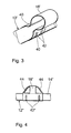
- FIG. 3 shows a short section of an atrial electrode line 12 ' an alternative longitudinal guide 18 ', the outside of the metal sleeve on the Electrode line 12 'is placed.
- the design of the metal sleeve 18 with Constrictions 40 are selected so that one in the metal sleeve 18 ' inserted ventricular lead a lateral distance to the atrial electrode line 12 'occupies.
- Figure 4 again shows a short section of an atrial Electrode line 12 "with longitudinal guide 18" attached to it.
- the Longitudinal guide 18 " is designed similarly to the longitudinal guide 18 'from FIG. 3 and, like this, has restraining constrictions 42 "that are generated, for example, by crimping.
- the Longitudinal guide 18 but also two slopes 44, which are in the manner of a Stents are designed like a bridge and are intended to prevent the Longitudinal guides 18 "when inserting the atrial electrode line 12" in Interlocking tissue.
- Figure 5 again shows a short section of an atrial Electrode line 12 "'with longitudinal guide 18' '' arranged thereon the longitudinal guide 18 "'is preferably made of metal such as Nitinol is formed and has to hold and guide along one ventricular electrode line two brackets 50.
- the Longitudinal guide 18 '' 'on two tongues 52 which surround the atrial electrode line 12 '' 'are molded around and are circumferential to the atrial Electrode line 12 "'overlap.
- the tongues 52 have one Function, the longitudinal guide 18 "'hold on the atrial lead 12' '' to give, by developing a corresponding bracket effect.
- the thickness of the tongues 52 ensures that one in the Longitudinal guide 18 '' 'located ventricular electrode line a distance from the atrial lead 12 '' '. Therefore, at Longitudinal guide 18 '' 'such constrictions as the constrictions 40 of the Longitudinal guide 18 'from Figure 3 are omitted.
- Figure 6 shows the distal end of an atrial electrode lead 12 '' '. With a longitudinal guide 18 "', as already described in Figure 5. From Figure 6 shows that the tip electrode 24 '' 'and the ring electrode 26 '' 'on the circumferential side of the atrial electrode catheter 12' '' are isolated when implanting a ventricular lead is facing and is led past this. This circumferential direction is determined by the orientation of the longitudinal guide 18 '' '.
- a cable 60 which within the ventricular lead and at its distal end exit.
- This cable is with the distal end of the atrial Electrode lead connected so that it is possible to connect the distal end of the atrial lead with the help of the cable in the direction of the distal Pull the end of the ventricular lead.
- the cable pull runs this purpose within the ventricular lead up to proximal end to be operated from there.
- the eyelet can be opposite the longitudinal axis the atrial lead, e.g. tilted by means of a cable that there is a jamming of the eyelet with one in the eyelet located ventricular lead comes, so both Electrode lines are fixed relative to each other.
- the eyelet on the atrial lead can also be used be otherwise deformable to prevent jamming with a Allow electrode lead in the eyelet.
- the atrial lead in the area of the eyelet e.g. S-shaped or otherwise bent to preform such that the Longitudinal axes of the atrial lead and ventricular Electrode leads in the area of the eye tend not to be parallel to run to each other so that there is tension between the eyelet and the second electrode line located in it comes.
- the first atrial lead is then inserted Preforming e.g. canceled by means of an appropriate stylet, see above that atrial and ventricular lead are slightly relative to each other are longitudinally displaceable.
- the atrial electrode lead also tilts the eyelet due to its preforming the ventricular lead and the two lead fixed relative to each other.
Landscapes
- Health & Medical Sciences (AREA)
- Heart & Thoracic Surgery (AREA)
- Life Sciences & Earth Sciences (AREA)
- Public Health (AREA)
- Engineering & Computer Science (AREA)
- Biomedical Technology (AREA)
- Nuclear Medicine, Radiotherapy & Molecular Imaging (AREA)
- Radiology & Medical Imaging (AREA)
- Vascular Medicine (AREA)
- Animal Behavior & Ethology (AREA)
- General Health & Medical Sciences (AREA)
- Cardiology (AREA)
- Veterinary Medicine (AREA)
- Measurement And Recording Of Electrical Phenomena And Electrical Characteristics Of The Living Body (AREA)
- Electrotherapy Devices (AREA)
- Measuring Pulse, Heart Rate, Blood Pressure Or Blood Flow (AREA)
- Electron Tubes For Measurement (AREA)
- Ceramic Capacitors (AREA)
- Secondary Cells (AREA)
Applications Claiming Priority (2)
| Application Number | Priority Date | Filing Date | Title |
|---|---|---|---|
| DE10153842 | 2001-10-24 | ||
| DE10153842A DE10153842A1 (de) | 2001-10-24 | 2001-10-24 | Elektrodenanordnung |
Publications (2)
| Publication Number | Publication Date |
|---|---|
| EP1306103A1 true EP1306103A1 (fr) | 2003-05-02 |
| EP1306103B1 EP1306103B1 (fr) | 2005-10-19 |
Family
ID=7704395
Family Applications (1)
| Application Number | Title | Priority Date | Filing Date |
|---|---|---|---|
| EP02090354A Expired - Lifetime EP1306103B1 (fr) | 2001-10-24 | 2002-10-15 | Ensemble d'électrodes |
Country Status (4)
| Country | Link |
|---|---|
| US (1) | US7561924B2 (fr) |
| EP (1) | EP1306103B1 (fr) |
| AT (1) | ATE306964T1 (fr) |
| DE (2) | DE10153842A1 (fr) |
Cited By (1)
| Publication number | Priority date | Publication date | Assignee | Title |
|---|---|---|---|---|
| EP2459274A4 (fr) * | 2009-07-30 | 2014-09-24 | Richard North | Electrode modulaire et outil d'insertion |
Families Citing this family (18)
| Publication number | Priority date | Publication date | Assignee | Title |
|---|---|---|---|---|
| US7082336B2 (en) | 2003-06-04 | 2006-07-25 | Synecor, Llc | Implantable intravascular device for defibrillation and/or pacing |
| US8239045B2 (en) | 2003-06-04 | 2012-08-07 | Synecor Llc | Device and method for retaining a medical device within a vessel |
| AU2004251673B2 (en) | 2003-06-04 | 2010-01-28 | Synecor Llc | Intravascular electrophysiological system and methods |
| US7617007B2 (en) * | 2003-06-04 | 2009-11-10 | Synecor Llc | Method and apparatus for retaining medical implants within body vessels |
| EP1701766A2 (fr) * | 2003-12-12 | 2006-09-20 | Synecor, LLC | Dispositif medical implantable possedant un exosquelette de pre-implantation |
| JP4680939B2 (ja) * | 2004-02-10 | 2011-05-11 | シネコー・エルエルシー | 治療薬用脈管内送達システム |
| US20050203600A1 (en) * | 2004-03-12 | 2005-09-15 | Scimed Life Systems, Inc. | Collapsible/expandable tubular electrode leads |
| US7590454B2 (en) * | 2004-03-12 | 2009-09-15 | Boston Scientific Neuromodulation Corporation | Modular stimulation lead network |
| US7231260B2 (en) | 2004-05-06 | 2007-06-12 | Boston Scientific Scimed, Inc. | Intravascular self-anchoring electrode body with arcuate springs, spring loops, or arms |
| US7937160B2 (en) | 2004-12-10 | 2011-05-03 | Boston Scientific Neuromodulation Corporation | Methods for delivering cortical electrode leads into patient's head |
| US20110009933A1 (en) * | 2009-07-09 | 2011-01-13 | Boston Scientific Neuromodulation Corporation | Piggy-back percutaneous lead insertion kit |
| US20130259357A1 (en) * | 2012-01-18 | 2013-10-03 | Cachet Financial Solutions Inc. | Remote deposit capture method and apparatus |
| US10098768B2 (en) * | 2014-09-15 | 2018-10-16 | Cook Medical Technologies Llc | Ratchet operated vascular intervention device delivery system |
| DE102018113594A1 (de) * | 2018-06-07 | 2019-12-12 | Biotronik Se & Co. Kg | Elektrodenleitung mit variabler, stufenloser Fixierungslänge |
| DE102018113593A1 (de) | 2018-06-07 | 2019-12-12 | Biotronik Se & Co. Kg | Elektrodenleitung mit variabler, stufenweise einstellbarer Fixierungslänge |
| IL299826A (en) | 2020-07-15 | 2023-03-01 | Cerebral Therapeutics Inc | A medical device with a non-filtered CSF withdrawal path |
| IL299904A (en) * | 2020-07-20 | 2023-03-01 | Cerebral Therapeutics Inc | A liquid catheter device for recording the state of the brain |
| US12605537B2 (en) | 2022-02-15 | 2026-04-21 | Biogen Ma Inc. | Implantable medical device for use with or having recording electrode |
Citations (5)
| Publication number | Priority date | Publication date | Assignee | Title |
|---|---|---|---|---|
| DE2605590A1 (de) * | 1976-02-12 | 1977-08-18 | Heinz Dr Med Praeuer | Herzschrittmacherelektrode |
| US5267958A (en) * | 1992-03-30 | 1993-12-07 | Medtronic, Inc. | Exchange catheter having exterior guide wire loops |
| US6056722A (en) * | 1997-09-18 | 2000-05-02 | Iowa-India Investments Company Limited Of Douglas | Delivery mechanism for balloons, drugs, stents and other physical/mechanical agents and methods of use |
| US6095990A (en) * | 1998-08-31 | 2000-08-01 | Parodi; Juan Carlos | Guiding device and method for inserting and advancing catheters and guidewires into a vessel of a patient in endovascular treatments |
| WO2001068177A1 (fr) * | 2000-03-10 | 2001-09-20 | Kensey Nash Corporation | Dispositif de raccordement d'un catheter sur un fil de guidage |
Family Cites Families (18)
| Publication number | Priority date | Publication date | Assignee | Title |
|---|---|---|---|---|
| US7205A (en) * | 1850-03-26 | Apparatus foe receiving and transferring to the pile sheets of paper | ||
| US4402329A (en) * | 1981-09-28 | 1983-09-06 | Medtronic, Inc. | Positive anchoring A-V lead |
| US4479500A (en) | 1982-09-16 | 1984-10-30 | Medtronic, Inc. | Pacing lead with A-V distance adapter |
| US4904431A (en) * | 1988-08-12 | 1990-02-27 | Baxter International, Inc. | Process for manufacturing catheters |
| US5107856A (en) * | 1991-01-10 | 1992-04-28 | Siemens-Pacesetter, Inc. | Multiple lead suture sleeve |
| US5706809A (en) * | 1993-01-29 | 1998-01-13 | Cardima, Inc. | Method and system for using multiple intravascular sensing devices to detect electrical activity |
| US5908446A (en) * | 1994-07-07 | 1999-06-01 | Cardiac Pathways Corporation | Catheter assembly, catheter and multi-port introducer for use therewith |
| DE4425195C1 (de) * | 1994-07-16 | 1995-11-16 | Osypka Peter | Katheter mit Mehrfachelektrode |
| US5674274A (en) * | 1995-12-14 | 1997-10-07 | Pacesetter, Inc. | Implantable adjustable single-pass A-V lead for use with an implantable stimulation device |
| US5954761A (en) * | 1997-03-25 | 1999-09-21 | Intermedics Inc. | Implantable endocardial lead assembly having a stent |
| US5957967A (en) | 1998-02-19 | 1999-09-28 | Medtronic, Inc. | Implantable medical lead using stamped conductor and distal loop |
| US6132456A (en) * | 1998-03-10 | 2000-10-17 | Medtronic, Inc. | Arrangement for implanting an endocardial cardiac lead |
| US5902331A (en) * | 1998-03-10 | 1999-05-11 | Medtronic, Inc. | Arrangement for implanting an endocardial cardiac lead |
| US6094596A (en) * | 1998-06-19 | 2000-07-25 | Angeron Corporation | Transvenous defibrillation lead system for use in middle cardiac vein |
| US6129749A (en) | 1998-08-25 | 2000-10-10 | Cardiac Pacemakers, Inc. | Monorail left ventricular access lead |
| EP1106202A3 (fr) * | 1999-11-30 | 2004-03-31 | BIOTRONIK Mess- und Therapiegeräte GmbH & Co Ingenieurbüro Berlin | Electrode de stimulation, cardioversion et/ou défibrillation intravasculaire |
| AU2001249877A1 (en) | 2000-04-13 | 2001-10-30 | Uab Research Foundation | Inter-atrial septum electrode for atrial defibrillation |
| US6574512B1 (en) * | 2000-08-28 | 2003-06-03 | Cardiac Pacemakers, Inc. | Lead system with main lead and transverse lead |
-
2001
- 2001-10-24 DE DE10153842A patent/DE10153842A1/de not_active Withdrawn
-
2002
- 2002-10-15 EP EP02090354A patent/EP1306103B1/fr not_active Expired - Lifetime
- 2002-10-15 AT AT02090354T patent/ATE306964T1/de not_active IP Right Cessation
- 2002-10-15 DE DE50204581T patent/DE50204581D1/de not_active Expired - Lifetime
- 2002-10-22 US US10/278,040 patent/US7561924B2/en not_active Expired - Fee Related
Patent Citations (5)
| Publication number | Priority date | Publication date | Assignee | Title |
|---|---|---|---|---|
| DE2605590A1 (de) * | 1976-02-12 | 1977-08-18 | Heinz Dr Med Praeuer | Herzschrittmacherelektrode |
| US5267958A (en) * | 1992-03-30 | 1993-12-07 | Medtronic, Inc. | Exchange catheter having exterior guide wire loops |
| US6056722A (en) * | 1997-09-18 | 2000-05-02 | Iowa-India Investments Company Limited Of Douglas | Delivery mechanism for balloons, drugs, stents and other physical/mechanical agents and methods of use |
| US6095990A (en) * | 1998-08-31 | 2000-08-01 | Parodi; Juan Carlos | Guiding device and method for inserting and advancing catheters and guidewires into a vessel of a patient in endovascular treatments |
| WO2001068177A1 (fr) * | 2000-03-10 | 2001-09-20 | Kensey Nash Corporation | Dispositif de raccordement d'un catheter sur un fil de guidage |
Cited By (1)
| Publication number | Priority date | Publication date | Assignee | Title |
|---|---|---|---|---|
| EP2459274A4 (fr) * | 2009-07-30 | 2014-09-24 | Richard North | Electrode modulaire et outil d'insertion |
Also Published As
| Publication number | Publication date |
|---|---|
| US20030097051A1 (en) | 2003-05-22 |
| DE10153842A1 (de) | 2003-05-08 |
| US7561924B2 (en) | 2009-07-14 |
| EP1306103B1 (fr) | 2005-10-19 |
| ATE306964T1 (de) | 2005-11-15 |
| DE50204581D1 (de) | 2005-11-24 |
Similar Documents
| Publication | Publication Date | Title |
|---|---|---|
| EP1306103B1 (fr) | Ensemble d'électrodes | |
| DE69632006T2 (de) | Führungsdrahteinheit | |
| DE69710062T2 (de) | Einführsystem mit auftrennbarer nichtknickender hülle | |
| DE69213336T2 (de) | Werkzeug zur Einführung und Tunnelung für subkutane Drahtgeflecht-Elektroden | |
| DE69635402T2 (de) | Führungseinheit mit internem Führungsdraht aus einer Formgedächtnislegierung | |
| DE69406445T2 (de) | Steuerbarer führungsdraht und betätigbare haltegriff-einheit | |
| DE602005002182T2 (de) | Flachdrahtspiralenelektrode benutzbar in einschraubbaren Herzstimulationsleitungen | |
| DE69525125T2 (de) | Medizinischer elektrischer Leiter mit verstärkten Zinken | |
| DE60017716T2 (de) | Coextrudierte medizinische multilumenleitung | |
| DE60023702T2 (de) | System zum einführen von kathetern | |
| DE69725302T2 (de) | Medizinische elektrische zuleitung | |
| DE60017962T2 (de) | Klemmvorrichtung zum Festklemmen einer Leitung | |
| DE19957241B4 (de) | Elektrische Leitung für medizinische Zwecke und System zur Einführung derselben | |
| DE2506694C2 (de) | Implantierbare, transvenös einführbare Elektrodenanordnung | |
| DE60015742T2 (de) | Medizinische elektrodenleitung | |
| DE69824425T2 (de) | Verbindungssystem für stimulationsleitungen | |
| DE602004006039T2 (de) | Multifunktioneller Handgriff für Katheter | |
| DE69936786T2 (de) | Temporärer atrialer elektrodenkatheter zur kardioversion | |
| DE60019908T2 (de) | Koronarsinusleitung | |
| DE69636709T2 (de) | Herzleitung mit isolierender Verbundstruktur | |
| DE2613044B2 (de) | Implantierbare elektrische Leitung | |
| DE8207842U1 (de) | Implantierbare leitung | |
| DE3507119A1 (de) | Regelbare endokardiale elektrodenanordnung | |
| DE10058106A1 (de) | Medizinische elektrische Leitung mit in Richtung des fernen ansteigender Biegesteifigkeit | |
| EP0779079B1 (fr) | Sonde à électrode unique pour stimulateurs cardiaques double chambre, en particulier pour stimulateurs cardiaques de type DD |
Legal Events
| Date | Code | Title | Description |
|---|---|---|---|
| PUAI | Public reference made under article 153(3) epc to a published international application that has entered the european phase |
Free format text: ORIGINAL CODE: 0009012 |
|
| AK | Designated contracting states |
Designated state(s): AT BE BG CH CY CZ DE DK EE ES FI FR GB GR IE IT LI LU MC NL PT SE SK TR |
|
| AX | Request for extension of the european patent |
Extension state: AL LT LV MK RO SI |
|
| 17P | Request for examination filed |
Effective date: 20030901 |
|
| AKX | Designation fees paid |
Designated state(s): AT BE BG CH CY CZ DE DK EE ES FI FR GB GR IE IT LI LU MC NL PT SE SK TR |
|
| 17Q | First examination report despatched |
Effective date: 20040716 |
|
| GRAP | Despatch of communication of intention to grant a patent |
Free format text: ORIGINAL CODE: EPIDOSNIGR1 |
|
| GRAS | Grant fee paid |
Free format text: ORIGINAL CODE: EPIDOSNIGR3 |
|
| GRAA | (expected) grant |
Free format text: ORIGINAL CODE: 0009210 |
|
| AK | Designated contracting states |
Kind code of ref document: B1 Designated state(s): AT BE BG CH CY CZ DE DK EE ES FI FR GB GR IE IT LI LU MC NL PT SE SK TR |
|
| PG25 | Lapsed in a contracting state [announced via postgrant information from national office to epo] |
Ref country code: IT Free format text: LAPSE BECAUSE OF FAILURE TO SUBMIT A TRANSLATION OF THE DESCRIPTION OR TO PAY THE FEE WITHIN THE PRE;WARNING: LAPSES OF ITALIAN PATENTS WITH EFFECTIVE DATE BEFORE 2007 MAY HAVE OCCURRED AT ANY TIME BEFORE 2007. THE CORRECT EFFECTIVE DATE MAY BE DIFFERENT FROM THE ONE RECORDED.SCRIBED TIME-LIMIT Effective date: 20051019 Ref country code: IE Free format text: LAPSE BECAUSE OF FAILURE TO SUBMIT A TRANSLATION OF THE DESCRIPTION OR TO PAY THE FEE WITHIN THE PRESCRIBED TIME-LIMIT Effective date: 20051019 Ref country code: FI Free format text: LAPSE BECAUSE OF FAILURE TO SUBMIT A TRANSLATION OF THE DESCRIPTION OR TO PAY THE FEE WITHIN THE PRESCRIBED TIME-LIMIT Effective date: 20051019 Ref country code: SK Free format text: LAPSE BECAUSE OF FAILURE TO SUBMIT A TRANSLATION OF THE DESCRIPTION OR TO PAY THE FEE WITHIN THE PRESCRIBED TIME-LIMIT Effective date: 20051019 Ref country code: CZ Free format text: LAPSE BECAUSE OF FAILURE TO SUBMIT A TRANSLATION OF THE DESCRIPTION OR TO PAY THE FEE WITHIN THE PRESCRIBED TIME-LIMIT Effective date: 20051019 |
|
| REG | Reference to a national code |
Ref country code: GB Ref legal event code: FG4D Free format text: NOT ENGLISH |
|
| REG | Reference to a national code |
Ref country code: CH Ref legal event code: EP Ref country code: CH Ref legal event code: NV Representative=s name: BRAUNPAT BRAUN EDER AG |
|
| GBT | Gb: translation of ep patent filed (gb section 77(6)(a)/1977) | ||
| REG | Reference to a national code |
Ref country code: IE Ref legal event code: FG4D Free format text: LANGUAGE OF EP DOCUMENT: GERMAN |
|
| REF | Corresponds to: |
Ref document number: 50204581 Country of ref document: DE Date of ref document: 20051124 Kind code of ref document: P |
|
| REG | Reference to a national code |
Ref country code: SE Ref legal event code: TRGR |
|
| PG25 | Lapsed in a contracting state [announced via postgrant information from national office to epo] |
Ref country code: DK Free format text: LAPSE BECAUSE OF FAILURE TO SUBMIT A TRANSLATION OF THE DESCRIPTION OR TO PAY THE FEE WITHIN THE PRESCRIBED TIME-LIMIT Effective date: 20060119 Ref country code: BG Free format text: LAPSE BECAUSE OF FAILURE TO SUBMIT A TRANSLATION OF THE DESCRIPTION OR TO PAY THE FEE WITHIN THE PRESCRIBED TIME-LIMIT Effective date: 20060119 Ref country code: GR Free format text: LAPSE BECAUSE OF FAILURE TO SUBMIT A TRANSLATION OF THE DESCRIPTION OR TO PAY THE FEE WITHIN THE PRESCRIBED TIME-LIMIT Effective date: 20060119 |
|
| PG25 | Lapsed in a contracting state [announced via postgrant information from national office to epo] |
Ref country code: ES Free format text: LAPSE BECAUSE OF FAILURE TO SUBMIT A TRANSLATION OF THE DESCRIPTION OR TO PAY THE FEE WITHIN THE PRESCRIBED TIME-LIMIT Effective date: 20060130 |
|
| PG25 | Lapsed in a contracting state [announced via postgrant information from national office to epo] |
Ref country code: PT Free format text: LAPSE BECAUSE OF FAILURE TO SUBMIT A TRANSLATION OF THE DESCRIPTION OR TO PAY THE FEE WITHIN THE PRESCRIBED TIME-LIMIT Effective date: 20060320 |
|
| REG | Reference to a national code |
Ref country code: IE Ref legal event code: FD4D |
|
| ET | Fr: translation filed | ||
| PLBE | No opposition filed within time limit |
Free format text: ORIGINAL CODE: 0009261 |
|
| STAA | Information on the status of an ep patent application or granted ep patent |
Free format text: STATUS: NO OPPOSITION FILED WITHIN TIME LIMIT |
|
| 26N | No opposition filed |
Effective date: 20060720 |
|
| PG25 | Lapsed in a contracting state [announced via postgrant information from national office to epo] |
Ref country code: MC Free format text: LAPSE BECAUSE OF NON-PAYMENT OF DUE FEES Effective date: 20061031 |
|
| BERE | Be: lapsed |
Owner name: BIOTRONIK MESS- UND THERAPIEGERATE G.M.B.H. & CO Effective date: 20061031 |
|
| PG25 | Lapsed in a contracting state [announced via postgrant information from national office to epo] |
Ref country code: AT Free format text: LAPSE BECAUSE OF NON-PAYMENT OF DUE FEES Effective date: 20061015 |
|
| PG25 | Lapsed in a contracting state [announced via postgrant information from national office to epo] |
Ref country code: EE Free format text: LAPSE BECAUSE OF FAILURE TO SUBMIT A TRANSLATION OF THE DESCRIPTION OR TO PAY THE FEE WITHIN THE PRESCRIBED TIME-LIMIT Effective date: 20051019 |
|
| PG25 | Lapsed in a contracting state [announced via postgrant information from national office to epo] |
Ref country code: TR Free format text: LAPSE BECAUSE OF FAILURE TO SUBMIT A TRANSLATION OF THE DESCRIPTION OR TO PAY THE FEE WITHIN THE PRESCRIBED TIME-LIMIT Effective date: 20051019 Ref country code: LU Free format text: LAPSE BECAUSE OF NON-PAYMENT OF DUE FEES Effective date: 20061015 |
|
| PG25 | Lapsed in a contracting state [announced via postgrant information from national office to epo] |
Ref country code: CY Free format text: LAPSE BECAUSE OF FAILURE TO SUBMIT A TRANSLATION OF THE DESCRIPTION OR TO PAY THE FEE WITHIN THE PRESCRIBED TIME-LIMIT Effective date: 20051019 |
|
| PGFP | Annual fee paid to national office [announced via postgrant information from national office to epo] |
Ref country code: NL Payment date: 20081023 Year of fee payment: 7 |
|
| PG25 | Lapsed in a contracting state [announced via postgrant information from national office to epo] |
Ref country code: BE Free format text: LAPSE BECAUSE OF FAILURE TO SUBMIT A TRANSLATION OF THE DESCRIPTION OR TO PAY THE FEE WITHIN THE PRESCRIBED TIME-LIMIT Effective date: 20061031 |
|
| PGFP | Annual fee paid to national office [announced via postgrant information from national office to epo] |
Ref country code: IT Payment date: 20081027 Year of fee payment: 7 |
|
| PGRI | Patent reinstated in contracting state [announced from national office to epo] |
Ref country code: IT Effective date: 20091201 |
|
| REG | Reference to a national code |
Ref country code: NL Ref legal event code: V1 Effective date: 20100501 |
|
| PG25 | Lapsed in a contracting state [announced via postgrant information from national office to epo] |
Ref country code: NL Free format text: LAPSE BECAUSE OF NON-PAYMENT OF DUE FEES Effective date: 20100501 |
|
| PGRI | Patent reinstated in contracting state [announced from national office to epo] |
Ref country code: IT Effective date: 20091201 |
|
| REG | Reference to a national code |
Representative=s name: RANDOLL, SOEREN, DIPL.-CHEM. UNIV. DR. RER. NA, DE Ref country code: DE Ref legal event code: R082 Ref document number: 50204581 Country of ref document: DE |
|
| REG | Reference to a national code |
Ref country code: DE Ref legal event code: R081 Ref document number: 50204581 Country of ref document: DE Owner name: BIOTRONIK SE & CO. KG, DE Free format text: FORMER OWNER: BIOTRONIK MESS- UND THERAPIEGERAETE GMBH & CO. INGENIEURBUERO BERLIN, 12359 BERLIN, DE Effective date: 20111219 |
|
| PGFP | Annual fee paid to national office [announced via postgrant information from national office to epo] |
Ref country code: FR Payment date: 20121113 Year of fee payment: 11 |
|
| PGFP | Annual fee paid to national office [announced via postgrant information from national office to epo] |
Ref country code: GB Payment date: 20121023 Year of fee payment: 11 Ref country code: SE Payment date: 20121024 Year of fee payment: 11 |
|
| REG | Reference to a national code |
Ref country code: SE Ref legal event code: EUG |
|
| GBPC | Gb: european patent ceased through non-payment of renewal fee |
Effective date: 20131015 |
|
| PG25 | Lapsed in a contracting state [announced via postgrant information from national office to epo] |
Ref country code: GB Free format text: LAPSE BECAUSE OF NON-PAYMENT OF DUE FEES Effective date: 20131015 |
|
| REG | Reference to a national code |
Ref country code: FR Ref legal event code: ST Effective date: 20140630 |
|
| PG25 | Lapsed in a contracting state [announced via postgrant information from national office to epo] |
Ref country code: SE Free format text: LAPSE BECAUSE OF NON-PAYMENT OF DUE FEES Effective date: 20131016 Ref country code: FR Free format text: LAPSE BECAUSE OF NON-PAYMENT OF DUE FEES Effective date: 20131031 |
|
| PGFP | Annual fee paid to national office [announced via postgrant information from national office to epo] |
Ref country code: DE Payment date: 20161014 Year of fee payment: 15 Ref country code: CH Payment date: 20161025 Year of fee payment: 15 |
|
| REG | Reference to a national code |
Ref country code: DE Ref legal event code: R119 Ref document number: 50204581 Country of ref document: DE |
|
| REG | Reference to a national code |
Ref country code: CH Ref legal event code: PCAR Free format text: NEW ADDRESS: HOLEESTRASSE 87, 4054 BASEL (CH) |
|
| REG | Reference to a national code |
Ref country code: CH Ref legal event code: PL |
|
| PG25 | Lapsed in a contracting state [announced via postgrant information from national office to epo] |
Ref country code: LI Free format text: LAPSE BECAUSE OF NON-PAYMENT OF DUE FEES Effective date: 20171031 Ref country code: DE Free format text: LAPSE BECAUSE OF NON-PAYMENT OF DUE FEES Effective date: 20180501 Ref country code: CH Free format text: LAPSE BECAUSE OF NON-PAYMENT OF DUE FEES Effective date: 20171031 |