EP1306106A2 - Module de bronzage avec un bôitier - Google Patents
Module de bronzage avec un bôitier Download PDFInfo
- Publication number
- EP1306106A2 EP1306106A2 EP02022555A EP02022555A EP1306106A2 EP 1306106 A2 EP1306106 A2 EP 1306106A2 EP 02022555 A EP02022555 A EP 02022555A EP 02022555 A EP02022555 A EP 02022555A EP 1306106 A2 EP1306106 A2 EP 1306106A2
- Authority
- EP
- European Patent Office
- Prior art keywords
- module according
- reflector
- radiation
- tanning module
- tanning
- Prior art date
- Legal status (The legal status is an assumption and is not a legal conclusion. Google has not performed a legal analysis and makes no representation as to the accuracy of the status listed.)
- Granted
Links
Images



Classifications
-
- A—HUMAN NECESSITIES
- A61—MEDICAL OR VETERINARY SCIENCE; HYGIENE
- A61N—ELECTROTHERAPY; MAGNETOTHERAPY; RADIATION THERAPY; ULTRASOUND THERAPY
- A61N5/00—Radiation therapy
- A61N5/06—Radiation therapy using light
- A61N5/0613—Apparatus adapted for a specific treatment
- A61N5/0614—Tanning
-
- A—HUMAN NECESSITIES
- A61—MEDICAL OR VETERINARY SCIENCE; HYGIENE
- A61N—ELECTROTHERAPY; MAGNETOTHERAPY; RADIATION THERAPY; ULTRASOUND THERAPY
- A61N5/00—Radiation therapy
- A61N2005/002—Cooling systems
- A61N2005/005—Cooling systems for cooling the radiator
Definitions
- the invention relates to a tanning module with a housing, one arranged in the housing three-dimensional reflector and at least one disc-shaped radiation filter, wherein the at least one radiation filter covers the radiation exit surface of the reflector and is arranged on a first side of the housing, at least in the reflector an opening is provided for the installation and electrical connection of a tanning lamp, and the reflector has its maximum cross section in the region of the radiation exit area having.
- Such tanning modules are known for example from DE 29 41 467 A1, wherein a rectangular housing including blower and flow guide plates can be used in the housing.
- the rectangular housing is divided into an air intake side and a pressure side, wherein the tanning lamp is arranged on the pressure side and is cooled indirectly.
- the Cooling air which flows along the filter disc and cools it, is sucked in on the Air intake side of the housing.
- the cooling air leaves the pressure side of the housing Housing through the same side wall as they were on the air intake side into the housing has arrived.
- DE 195 16 603 A1 discloses a low-pressure field of view for tanning devices, one of which rectangular housing including reflector and filter disc is used.
- the housing is suitable for the installation of several UVC tubes. Cooling air is admitted into the housing through an opening between the housing and filter disc, the cooling air along the Tubes flow and leave the housing on the back of the housing.
- DE 36 31 427 C2 describes an irradiation device with a rectangular housing and Reflector and filter disc. It is a low power device, so cooling of the tanning lamp or of the reflector is not provided. To secure of the filter against breakage, a pressure switch is provided which is pressed in by the filter plate Position is fixed, however, in the event of breakage, this position emerges and the Radiation source switches off.
- DE 39 27 695 C2 discloses a tanning device with a pivotably arranged interference filter.
- An infrared filter is arranged downstream of the interference filter in the beam exit direction.
- the limit of the transmission spectrum depends on the inclination of the interference filter in the radiation exit shifted to the shorter-wave UV-B portion or to the longer-wave UV-A portion. By swiveling the filter, the radiation spectrum is thus towards the skin type irradiating person adjustable.
- DE 40 37 483 C2 describes a UV radiation device with breakage protection for a filter glass pane, a current-carrying electrical conductor track being arranged on its circumference is. If the filter glass pane breaks, the conductor path and thus the current is interrupted and the tanning lamp switched off.
- the housing on an opposite of the radiation filter second side in the form of a saddle roof, a hipped roof or a half-hipped roof is configured, the roof ridge being flattened and pointing away from the radiation filter.
- Such a housing shape has the advantage that the free cross section between the outside of the reflector and the inside of the housing can be kept small, so that one Extracting air from the area behind the reflector is a relatively uniform Flow distribution arises. The temperature of the reflector is evened out. Additional flow baffles can be dispensed with in the tanning module according to the invention as the formation of fluidically "dead corners" can be avoided. In the area of the opening of the reflector for installation and connection a tanning lamp, air can also be drawn from the reflector room and thus the tanning lamps can be cooled directly.
- the tanning module according to the invention is for tanning lamps with an electrical output suitable in the range from 250W to 1000W. It is outstanding in a wide variety Tanning equipment or medical equipment for irradiating the visual field, the Cleavage area, body area, leg or foot area can be used. Even the installation in ceilings, for example for irradiating lying surfaces from larger distances, is possible.
- the tanning module according to the invention can basically in any kind of Bracket can be mounted so that it can shine in all directions of a virtual ball.
- Several tanning modules can be installed side by side or one after the other, to create a larger radiation field. There is an option for each tanning module to work with a separate fan or multiple tanning modules with one to operate the central fan.
- the radiation filter is preferably aligned parallel to the radiation exit surface of the reflector.
- the flattened roof ridge can be formed by a flat housing wall part, whereby this can be aligned parallel to the radiation filter.
- the flattened roof ridge can also be formed by a curved part of the housing wall, this with regard to the radiation filter can be concave or convex. It has been particularly proven when on the gable roof, the hip roof or the half-hipped roof in the direction of the radiation filter connects a rectangular housing wall area. In this can for example, the radiation filter is recorded.
- a cup-shaped or trough-shaped reflector is particularly preferred, the cup or trough bottom of the reflector either curved or plane-parallel to the at least a radiation filter can be implemented.
- a circumference of the reflector parallel to the radiation exit surface preferably describes a circle, an ellipse, a rectangle or a polygon. It is preferred if the reflector is formed from facets and the circumference of the reflector describes a polygon with twelve corners parallel to the radiation exit surface.
- a reflector with a height in the range from 90 mm to 95 mm is particularly suitable has and is in particular 93.6 mm high.
- the dodecagon in the plane of the radiation exit surface preferably has a maximum diameter (from corner to corner) in the area from 210 mm to 230 mm and is in particular 210 mm.
- Another suitable reflector has a height in the range from 110 mm to 125 mm and is especially 118.7 mm high.
- the dodecagon in the plane of the radiation exit surface points preferably a maximum diameter (from corner to corner) in the range from 170 mm to 200 mm and is in particular 184 mm.
- Another suitable reflector has a height in the range from 75 mm to 90 mm and is in particular 83.3 mm high.
- the dodecagon in the plane of the radiation exit surface points preferably a maximum diameter (from corner to corner) in the range from 205 mm to 235 mm and is in particular 220 mm.
- the routing of the cooling air flow in the housing is optimized in particular if at least there is an air extraction opening in the area of the sloping ceilings. It can at the Air extraction opening, a flange may be attached. For extracting cooling air from the housing an air suction hose can be arranged on the flange. About such an air suction hose central or decentralized air extraction is possible.
- a reducing disk can be provided to reduce the size of the air extraction opening. This is useful, for example, if several tanning modules are used and these are at different distances from a central fan, ie fans used at the same time by all tanning modules, or the air is extracted in a kind of series connection from one tanning module to at least one other fan.
- At least one holder for electrical connections is preferably on the outside of the housing or components arranged, wherein as components, here for example an igniter Pushbuttons or an earthing strap are possible.
- a suction plate between the housing and the reflector, the radiation exit surface of the reflector being shifted up or down to the plane of the suction plate, at least one suction opening being formed between the suction plate and reflector and the suction plate having a recess for the reflector which has the size of the radiation exit surface of the reflector in the vertical projection onto the at least one radiation filter.
- This arrangement of the reflector with respect to the suction plate preferably forms an annular suction opening between the suction plate and the reflector, through which cooling air can be drawn off from the area between the radiation filter and the radiation exit surface of the reflector in the direction of the outer wall of the reflector.
- a plurality of suction openings preferably arranged in a ring, can also be formed between the suction plate and the reflector, with a possible symmetrical alignment of the suction openings having a positive effect on the uniformity of the cooling of the reflector and the radiation filter.
- the temperature distribution on the radiation filter has a decisive influence on its transmission properties.
- a suction plate covers the housing and the reflector on all sides connects in the area of the radiation exit surface of the reflector, the suction plate has at least one suction opening and also has a recess for the reflector, the size in the vertical projection onto the at least one radiation filter the radiation exit surface of the reflector.
- the suction plate has a rectangular circumference, the circumference of the reflector describing a circle, an ellipse or a polygon parallel to the radiation exit surface, and the at least one suction opening being arranged in the region of a corner of the suction plate. It is preferred that four suction openings are formed in the suction plate and that one suction opening is arranged in each corner of the suction plate. It has proven to be favorable from a fluidic point of view if the at least one suction opening is enlarged along the sides of the suction plate.
- the suction opening can be trapezoidal, for example, the long side of the trapezoid pointing towards the reflector. The long side of the trapezoid and its opposite side can be curved.
- the at least one radiation filter can preferably be detached from the housing via a swivel mechanism.
- the pivoting mechanism is intended to enable the radiation filter to be tilted with respect to the housing, and the radiation filter should only be released from the housing after the tilted radiation filter has been displaced in the housing. This enables a user-friendly replacement of the radiation filter and also prevents the radiation filter from falling suddenly, since such a pivoting mechanism can effectively prevent the radiation filter from falling and thus breaking.
- Attaching the radiation filter to the housing is particularly simple if the at least one radiation filter is rectangular.
- the at least one radiation filter with a length and a width in the range from 215 mm to 240 mm is preferred.
- the at least one radiation filter has a length of 230 mm and a width of 225 mm.
- the at least one radiation filter is preferably an interference filter, since with it the UV portion can be dosed and the visible part of the light can be suppressed.
- An embodiment of the tanning module is preferred in which there is a first radiation filter and a second radiation filter parallel to it, the second radiation filter being arranged between the radiation exit surface of the reflector and the first radiation filter and the first radiation filter being the interference filter.
- the second radiation filter is then preferably a UV filter or an infrared filter.
- At least one push button can be arranged on the housing, which is placed on the at least one radiation filter.
- the pushbutton can be guided through the reflector perpendicular to the radiation exit surface of the reflector or can be guided perpendicular to the radiation exit surface of the reflector through the suction plate.
- the push button can also be arranged on the suction plate and placed on the at least one radiation filter. If the monitored radiation filter breaks, the power supply of the tanning lamp is interrupted by changing the position of the push button and the user is protected from an uncontrolled dose of radiation.
- Tanning module according to one of claims 1 to 39, characterized in that a base (13) in the area of the opening of the reflector (3a, 3b) for mechanical and electrical Connection of a tanning lamp is provided.
- Tanning module according to one of claims 21 to 40, characterized in that between the at least one radiation filter (2a, 2b) and the suction plate (10) a cover plate is arranged, which is arranged spaced from the suction plate (10) and which has a recess, which in the vertical projection onto the at least one radiation filter has the size of the radiation exit surface of the reflector (3a, 3b).
- a mechanical and electrical connection Tanning lamp preferably provided a base.
- a cover plate can be placed between the at least one radiation filter and the suction plate be arranged, which is arranged spaced from the suction plate and which has a recess has that in the vertical projection onto the at least one radiation filter has the size of the radiation exit area of the reflector.
- This cover plate covered any suction openings for cooling air in the suction plate in front of the eye of the user.
- the housing is rectangular in the area of the radiation filter is and ends on all four sides with a fold, the four folds parallel are aligned with the radiation filter. Two opposite folds of the four folds point to the radiation filter and the other two opposite folds of the Point four folds away from the radiation filter.
- Such a configuration is then particularly closed recommend if several tanning modules are used side by side in one tanning device should be, so that in particular the folds pointing away from the radiation filter in the Transition area between two tanning modules the view of the rear area of the tanning module.
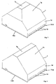
- FIG. 1 shows the housing 1 of a tanning module in a three-dimensional view, wherein here is in the form of a half-hipped roof 1b with a flattened roof ridge 1a.
- To the Roof construction connects a rectangular housing wall area 1d, which in four folds ends, with two folds 14b, 14d pointing outwards and the two remaining folds (not here visible) point inwards. Air intake openings are in the rectangular housing wall area 1d 12 available.
- FIG. 2 shows a further housing 1 of a tanning module in a three-dimensional view, here the shape of a saddle roof 1c with a flattened roof ridge 1a is present.
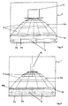
- FIG. 3 shows a tanning module with a housing 1 according to FIG. 1 in cross section to Roof ridge, with a reflector 3a formed from facets 4.
- the reflector 3a is connected to a suction plate 10 via spacers, with cooling air between the spacers can be sucked into the space between reflector 3a and housing 1.
- in the Rectangular housing wall area 1d are a rectangular first radiation filter 2a and a rectangular second radiation filter 2b is present.
- the folds 14a, 14c can also be seen, that point to the radiation filters.
- FIG. 4 shows a tanning module with a housing according to FIG. 2 in cross section to Roof ridge, with a reflector 3b formed from facets 4.
- the reflector 3b is connected to a suction plate 10, cooling air via suction openings in the space between Reflector 3b and housing 1 can be sucked.
- the rectangular housing wall area 1d are a rectangular first radiation filter 2a and a rectangular second radiation filter 2b.
- the base 13 recognizable for receiving a tanning lamp in the opening of the reflector 3b.
- an air suction opening 5 on the roof to which a flange 6 is attached.
- a holder 8 for fastening an igniter 9.
- FIG. 5 shows a further tanning module with a housing 1 according to FIG. 1 in section along the ridge.
- the reflector 3b is spaced from the suction plate 10 with the housing 1, wherein cooling air between the suction plate 10 and the reflector 3b in the Space between reflector 3b and housing 1 can be sucked.
- Figure 6 shows a further tanning module with a housing according to Figure 2 in longitudinal section of the roof ridge.
- the reflector 3b is connected to the suction plate 10, with cooling air via Intake openings can be sucked into the space between the reflector 3b and the housing 1.
- Figure 7 shows a suction plate 10 including four suction openings 11 and a recess 10a for a twelve-sided reflector.
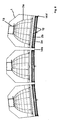
- FIG. 8 shows three tanning modules with a housing according to FIG. 1 in cross section to Roof ridge, the arrangement showing the connection of the folds 14b, 14d from module to module.
- FIG. 9 shows a three-dimensional view of a number of tanning modules mounted side by side.
- a tanning module with the radiation filter closed is shown on the far left.
- On the far right is a tanning module without a radiation filter and without a tanning lamp shown. All three modules are provided with air suction hoses 7.
Landscapes
- Health & Medical Sciences (AREA)
- Engineering & Computer Science (AREA)
- Biomedical Technology (AREA)
- General Health & Medical Sciences (AREA)
- Veterinary Medicine (AREA)
- Radiology & Medical Imaging (AREA)
- Life Sciences & Earth Sciences (AREA)
- Animal Behavior & Ethology (AREA)
- Pathology (AREA)
- Public Health (AREA)
- Nuclear Medicine, Radiotherapy & Molecular Imaging (AREA)
- Radiation-Therapy Devices (AREA)
- Cooling Or The Like Of Electrical Apparatus (AREA)
- Orthopedics, Nursing, And Contraception (AREA)
- Measuring Pulse, Heart Rate, Blood Pressure Or Blood Flow (AREA)
- Aerials With Secondary Devices (AREA)
- Arrangement Of Elements, Cooling, Sealing, Or The Like Of Lighting Devices (AREA)
- Led Device Packages (AREA)
Applications Claiming Priority (2)
| Application Number | Priority Date | Filing Date | Title |
|---|---|---|---|
| DE10151850A DE10151850A1 (de) | 2001-10-24 | 2001-10-24 | Bräunungsmodul mit einem Gehäuse |
| DE10151850 | 2001-10-24 |
Publications (3)
| Publication Number | Publication Date |
|---|---|
| EP1306106A2 true EP1306106A2 (fr) | 2003-05-02 |
| EP1306106A3 EP1306106A3 (fr) | 2003-12-10 |
| EP1306106B1 EP1306106B1 (fr) | 2008-03-26 |
Family
ID=7703172
Family Applications (1)
| Application Number | Title | Priority Date | Filing Date |
|---|---|---|---|
| EP02022555A Expired - Lifetime EP1306106B1 (fr) | 2001-10-24 | 2002-10-08 | Module de bronzage avec un boitier |
Country Status (6)
| Country | Link |
|---|---|
| US (1) | US6837900B2 (fr) |
| EP (1) | EP1306106B1 (fr) |
| AT (1) | ATE390173T1 (fr) |
| DE (2) | DE10151850A1 (fr) |
| DK (1) | DK1306106T3 (fr) |
| ES (1) | ES2304412T3 (fr) |
Cited By (1)
| Publication number | Priority date | Publication date | Assignee | Title |
|---|---|---|---|---|
| EP1515085A3 (fr) * | 2003-09-15 | 2013-07-24 | Heraeus Noblelight GmbH | Ensemble lampe UV et son utilisation |
Families Citing this family (11)
| Publication number | Priority date | Publication date | Assignee | Title |
|---|---|---|---|---|
| DE10151841B4 (de) * | 2001-10-24 | 2007-02-08 | Heraeus Noblelight Gmbh | Rechteckige Rahmenanordnung mit ein bis zwei scheibenförmigen Strahlungsfiltern und Bräunungsmodul |
| NL1021009C2 (nl) * | 2002-07-05 | 2004-01-09 | Sunshower B V | Douche-inrichting met bruiningsinrichting. |
| ITVI20060105A1 (it) | 2006-04-07 | 2007-10-08 | I So Italia Spa | Riflettore per lampade uv, nonche' lampada ed apparato di abbronzatura comprendente tale riflettore |
| US8801235B2 (en) | 2010-01-08 | 2014-08-12 | Best Lights | Lighting assembly |
| US8641239B2 (en) * | 2010-01-08 | 2014-02-04 | Best Lights, Inc. | Reflector for a lighting assembly |
| US20120134162A1 (en) * | 2010-05-27 | 2012-05-31 | David Hanacek | Recessed Lighting Enclosure and Insulation Barrier |
| US20120060757A1 (en) * | 2010-09-15 | 2012-03-15 | Yu Jen Li | Uv curing apparatus utilizing a cold cathode florescent lamp |
| NL2030285B1 (en) * | 2021-12-24 | 2023-06-30 | Sunshower Ip Bv | Device for radiating UV and/or IR radiation to a human body in a humid room |
| NL2030283B1 (en) * | 2021-12-24 | 2023-06-30 | Sunshower Ip Bv | Device for radiating UV and/or IR radiation to a human body in a humid room |
| NL2030286B1 (en) * | 2021-12-24 | 2023-06-30 | Sunshower Ip Bv | Device for radiating UV and/or IR radiation to a human body in a humid room |
| NL2030284B1 (en) * | 2021-12-24 | 2023-06-30 | Sunshower Ip Bv | Device for radiating UV and/or IR radiation to a human body in a humid room |
Citations (5)
| Publication number | Priority date | Publication date | Assignee | Title |
|---|---|---|---|---|
| DE2941467A1 (de) | 1979-10-12 | 1981-04-23 | Hans Robert Dr. Innsbruck Sellmeier | Braeunungsgeraet fuer direktpigmentierung |
| DE3927695C2 (de) | 1989-08-22 | 1995-04-20 | Kratz Josef Gmbh | Bräunungsgerät |
| DE3631427C2 (de) | 1985-09-17 | 1996-02-15 | Philips Electronics Nv | Bestrahlungsgerät |
| DE19516603A1 (de) | 1995-05-09 | 1996-11-14 | Imab Stiftung | Niederdruckgesichtsfeld für Bräunungsgeräte |
| DE4037483C2 (de) | 1990-11-24 | 2000-06-29 | Uwe Unterwasser Electric Gmbh | UV-Bestrahlungsgerät, insbesondere an einer Bräunnungsliege |
Family Cites Families (12)
| Publication number | Priority date | Publication date | Assignee | Title |
|---|---|---|---|---|
| FR711054A (fr) | 1930-02-14 | 1931-09-02 | Thomson Houston Comp Francaise | Perfectionnements aux sources de radiations et à leur appareillage |
| DE2609273A1 (de) * | 1976-03-05 | 1977-09-08 | Mutzhas Maximilian F | Bestrahlungseinrichtung mit ultraviolett-strahlenquelle |
| DE9210776U1 (de) | 1991-12-21 | 1992-12-17 | Callux Leuchten GmbH, 7260 Calw | Leuchtstoffröhrenleuchte |
| US5720772A (en) * | 1992-10-20 | 1998-02-24 | Esc Medical Systems Ltd. | Method and apparatus for therapeutic electromagnetic treatment |
| DE9303352U1 (de) * | 1993-03-08 | 1993-07-22 | Elfo Ag Sachseln, Sachseln | Infrarotbestrahlungslampe mit einer im Strahlungsgang befindlichen Küvette |
| DE4323936A1 (de) | 1993-07-16 | 1995-01-19 | Harald Handwerk | Helio-Dynamik, Bestrahlungsgerät zur Ganzkörperbestrahlung zu Gesunderhaltung und Vitalisierung mit sonnenlichtähnlicher Lichtqualität |
| JP2814195B2 (ja) * | 1994-03-30 | 1998-10-22 | 修 島田 | 温きゅう器 |
| DE29517716U1 (de) * | 1995-11-08 | 1996-01-25 | Herbert Waldmann GmbH & Co, 78056 Villingen-Schwenningen | Gerät zur fotodynamischen Bestrahlung |
| US5743632A (en) * | 1996-11-12 | 1998-04-28 | The Genlyte Group Incorporated | Thermally controlled light fixture |
| US6228074B1 (en) * | 1998-10-15 | 2001-05-08 | Stephen Almeida | Multiple pulse photo-epilator |
| DE20117223U1 (de) * | 2001-10-24 | 2002-01-17 | Heraeus Noblelight Gmbh, 63450 Hanau | Bräunungsmodul mit einem Gehäuse |
| US6649921B1 (en) * | 2002-08-19 | 2003-11-18 | Fusion Uv Systems, Inc. | Apparatus and method providing substantially two-dimensionally uniform irradiation |
-
2001
- 2001-10-24 DE DE10151850A patent/DE10151850A1/de not_active Withdrawn
-
2002
- 2002-09-27 US US10/256,404 patent/US6837900B2/en not_active Expired - Fee Related
- 2002-10-08 AT AT02022555T patent/ATE390173T1/de not_active IP Right Cessation
- 2002-10-08 DE DE50211952T patent/DE50211952D1/de not_active Expired - Fee Related
- 2002-10-08 ES ES02022555T patent/ES2304412T3/es not_active Expired - Lifetime
- 2002-10-08 DK DK02022555T patent/DK1306106T3/da active
- 2002-10-08 EP EP02022555A patent/EP1306106B1/fr not_active Expired - Lifetime
Patent Citations (5)
| Publication number | Priority date | Publication date | Assignee | Title |
|---|---|---|---|---|
| DE2941467A1 (de) | 1979-10-12 | 1981-04-23 | Hans Robert Dr. Innsbruck Sellmeier | Braeunungsgeraet fuer direktpigmentierung |
| DE3631427C2 (de) | 1985-09-17 | 1996-02-15 | Philips Electronics Nv | Bestrahlungsgerät |
| DE3927695C2 (de) | 1989-08-22 | 1995-04-20 | Kratz Josef Gmbh | Bräunungsgerät |
| DE4037483C2 (de) | 1990-11-24 | 2000-06-29 | Uwe Unterwasser Electric Gmbh | UV-Bestrahlungsgerät, insbesondere an einer Bräunnungsliege |
| DE19516603A1 (de) | 1995-05-09 | 1996-11-14 | Imab Stiftung | Niederdruckgesichtsfeld für Bräunungsgeräte |
Cited By (1)
| Publication number | Priority date | Publication date | Assignee | Title |
|---|---|---|---|---|
| EP1515085A3 (fr) * | 2003-09-15 | 2013-07-24 | Heraeus Noblelight GmbH | Ensemble lampe UV et son utilisation |
Also Published As
| Publication number | Publication date |
|---|---|
| DE10151850A1 (de) | 2003-05-15 |
| ES2304412T3 (es) | 2008-10-16 |
| ATE390173T1 (de) | 2008-04-15 |
| US6837900B2 (en) | 2005-01-04 |
| EP1306106B1 (fr) | 2008-03-26 |
| DK1306106T3 (da) | 2008-06-23 |
| US20030078635A1 (en) | 2003-04-24 |
| EP1306106A3 (fr) | 2003-12-10 |
| DE50211952D1 (de) | 2008-05-08 |
Similar Documents
| Publication | Publication Date | Title |
|---|---|---|
| DE3733904C1 (de) | Linear-polarisiertes Licht ausstrahlende Behandlungsleuchte | |
| EP1306106B1 (fr) | Module de bronzage avec un boitier | |
| EP1845396A1 (fr) | Eclairage doté d'au moins une couverture transparente | |
| EP1288561B1 (fr) | Dispositif d'éclairage, notamment dispositif de signalisation d'urgence et éolienne avec un tel dispositif | |
| DE102021103957A1 (de) | Rettungszeichenleuchte mit Rettungswegbeleuchtung | |
| EP3671680A1 (fr) | Détecteur d'incendie ou de fumée | |
| DE2210242A1 (de) | Beleuchtungskörper | |
| DE20117223U1 (de) | Bräunungsmodul mit einem Gehäuse | |
| DE2701948A1 (de) | Operationsleuchte | |
| EP2392854A2 (fr) | Lampe destinée à la production d'un éclairage indirect modifiable | |
| DE10058721A1 (de) | Operationsleuchte an einem Deckenarmsystem | |
| EP0677697B1 (fr) | Appareil d'éclairage pour plan de travail | |
| EP3187773A1 (fr) | Corps lumineux et lampadaire | |
| EP3919122A2 (fr) | Chambre de luminothérapie pourvu d'au moins deux unités de commande et/ou de surveillance et procédé de surveillance d'une chambre de luminothérapie | |
| DE602004004862T2 (de) | Signalleuchte mit lichtemittierenden Dioden | |
| DE102020126096A1 (de) | Vorrichtung zur reinigung von raumluft | |
| EP2472177B1 (fr) | Eclairage | |
| DE102022123220A1 (de) | Optische vorrichtung für die desinfektion oberer luftschichten in einem raum | |
| AT6831U1 (de) | Beleuchtungsvorrichtung, insbesondere für strassen, wege, plätze od. dgl. | |
| DE19607872C2 (de) | Leuchte mit Bewegungsmelder | |
| DE2929805A1 (de) | Entkeimungsgeraet | |
| EP1843086A1 (fr) | Lampe à réflecteur | |
| DE3610724A1 (de) | Klimatisiertes bestrahlungsgeraet | |
| DE9413076U1 (de) | Polarisiertes Licht ausstrahlende Behandlungsleuchte für den Handbetrieb | |
| DE202022106468U1 (de) | Eine Ultraviolettdesinfektionslampenstruktur und eine Ultraviolettdesinfektionsleuchte |
Legal Events
| Date | Code | Title | Description |
|---|---|---|---|
| PUAI | Public reference made under article 153(3) epc to a published international application that has entered the european phase |
Free format text: ORIGINAL CODE: 0009012 |
|
| 17P | Request for examination filed |
Effective date: 20021017 |
|
| AK | Designated contracting states |
Designated state(s): AT BE BG CH CY CZ DE DK EE ES FI FR GB GR IE IT LI LU MC NL PT SE SK TR |
|
| AX | Request for extension of the european patent |
Extension state: AL LT LV MK RO SI |
|
| PUAL | Search report despatched |
Free format text: ORIGINAL CODE: 0009013 |
|
| AK | Designated contracting states |
Kind code of ref document: A3 Designated state(s): AT BE BG CH CY CZ DE DK EE ES FI FR GB GR IE IT LI LU MC NL PT SE SK TR |
|
| AX | Request for extension of the european patent |
Extension state: AL LT LV MK RO SI |
|
| AKX | Designation fees paid |
Designated state(s): AT BE BG CH CY CZ DE DK EE ES FI FR GB GR IE IT LI LU MC NL PT SE SK TR |
|
| GRAP | Despatch of communication of intention to grant a patent |
Free format text: ORIGINAL CODE: EPIDOSNIGR1 |
|
| GRAS | Grant fee paid |
Free format text: ORIGINAL CODE: EPIDOSNIGR3 |
|
| GRAA | (expected) grant |
Free format text: ORIGINAL CODE: 0009210 |
|
| AK | Designated contracting states |
Kind code of ref document: B1 Designated state(s): AT BE BG CH CY CZ DE DK EE ES FI FR GB GR IE IT LI LU MC NL PT SE SK TR |
|
| REG | Reference to a national code |
Ref country code: GB Ref legal event code: FG4D Free format text: NOT ENGLISH |
|
| REG | Reference to a national code |
Ref country code: CH Ref legal event code: EP Ref country code: IE Ref legal event code: FG4D Free format text: LANGUAGE OF EP DOCUMENT: GERMAN |
|
| REF | Corresponds to: |
Ref document number: 50211952 Country of ref document: DE Date of ref document: 20080508 Kind code of ref document: P |
|
| REG | Reference to a national code |
Ref country code: DK Ref legal event code: T3 |
|
| REG | Reference to a national code |
Ref country code: SE Ref legal event code: TRGR |
|
| PG25 | Lapsed in a contracting state [announced via postgrant information from national office to epo] |
Ref country code: FI Free format text: LAPSE BECAUSE OF FAILURE TO SUBMIT A TRANSLATION OF THE DESCRIPTION OR TO PAY THE FEE WITHIN THE PRESCRIBED TIME-LIMIT Effective date: 20080326 |
|
| REG | Reference to a national code |
Ref country code: ES Ref legal event code: FG2A Ref document number: 2304412 Country of ref document: ES Kind code of ref document: T3 |
|
| REG | Reference to a national code |
Ref country code: IE Ref legal event code: FD4D |
|
| PG25 | Lapsed in a contracting state [announced via postgrant information from national office to epo] |
Ref country code: PT Free format text: LAPSE BECAUSE OF FAILURE TO SUBMIT A TRANSLATION OF THE DESCRIPTION OR TO PAY THE FEE WITHIN THE PRESCRIBED TIME-LIMIT Effective date: 20080901 Ref country code: CZ Free format text: LAPSE BECAUSE OF FAILURE TO SUBMIT A TRANSLATION OF THE DESCRIPTION OR TO PAY THE FEE WITHIN THE PRESCRIBED TIME-LIMIT Effective date: 20080326 Ref country code: SK Free format text: LAPSE BECAUSE OF FAILURE TO SUBMIT A TRANSLATION OF THE DESCRIPTION OR TO PAY THE FEE WITHIN THE PRESCRIBED TIME-LIMIT Effective date: 20080326 |
|
| PGFP | Annual fee paid to national office [announced via postgrant information from national office to epo] |
Ref country code: NL Payment date: 20081015 Year of fee payment: 7 |
|
| EN | Fr: translation not filed | ||
| PG25 | Lapsed in a contracting state [announced via postgrant information from national office to epo] |
Ref country code: IE Free format text: LAPSE BECAUSE OF FAILURE TO SUBMIT A TRANSLATION OF THE DESCRIPTION OR TO PAY THE FEE WITHIN THE PRESCRIBED TIME-LIMIT Effective date: 20080326 |
|
| PGFP | Annual fee paid to national office [announced via postgrant information from national office to epo] |
Ref country code: DE Payment date: 20081022 Year of fee payment: 7 Ref country code: DK Payment date: 20081015 Year of fee payment: 7 |
|
| PLBE | No opposition filed within time limit |
Free format text: ORIGINAL CODE: 0009261 |
|
| STAA | Information on the status of an ep patent application or granted ep patent |
Free format text: STATUS: NO OPPOSITION FILED WITHIN TIME LIMIT |
|
| PGFP | Annual fee paid to national office [announced via postgrant information from national office to epo] |
Ref country code: ES Payment date: 20081027 Year of fee payment: 7 |
|
| 26N | No opposition filed |
Effective date: 20081230 |
|
| PGFP | Annual fee paid to national office [announced via postgrant information from national office to epo] |
Ref country code: BE Payment date: 20081120 Year of fee payment: 7 Ref country code: IT Payment date: 20081022 Year of fee payment: 7 Ref country code: SE Payment date: 20081014 Year of fee payment: 7 |
|
| PG25 | Lapsed in a contracting state [announced via postgrant information from national office to epo] |
Ref country code: FR Free format text: LAPSE BECAUSE OF FAILURE TO SUBMIT A TRANSLATION OF THE DESCRIPTION OR TO PAY THE FEE WITHIN THE PRESCRIBED TIME-LIMIT Effective date: 20090116 Ref country code: EE Free format text: LAPSE BECAUSE OF FAILURE TO SUBMIT A TRANSLATION OF THE DESCRIPTION OR TO PAY THE FEE WITHIN THE PRESCRIBED TIME-LIMIT Effective date: 20080326 Ref country code: BG Free format text: LAPSE BECAUSE OF FAILURE TO SUBMIT A TRANSLATION OF THE DESCRIPTION OR TO PAY THE FEE WITHIN THE PRESCRIBED TIME-LIMIT Effective date: 20080626 |
|
| PG25 | Lapsed in a contracting state [announced via postgrant information from national office to epo] |
Ref country code: MC Free format text: LAPSE BECAUSE OF NON-PAYMENT OF DUE FEES Effective date: 20081031 |
|
| REG | Reference to a national code |
Ref country code: CH Ref legal event code: PL |
|
| PGFP | Annual fee paid to national office [announced via postgrant information from national office to epo] |
Ref country code: GB Payment date: 20081021 Year of fee payment: 7 |
|
| PG25 | Lapsed in a contracting state [announced via postgrant information from national office to epo] |
Ref country code: CY Free format text: LAPSE BECAUSE OF FAILURE TO SUBMIT A TRANSLATION OF THE DESCRIPTION OR TO PAY THE FEE WITHIN THE PRESCRIBED TIME-LIMIT Effective date: 20080326 |
|
| PG25 | Lapsed in a contracting state [announced via postgrant information from national office to epo] |
Ref country code: CH Free format text: LAPSE BECAUSE OF NON-PAYMENT OF DUE FEES Effective date: 20081031 Ref country code: LI Free format text: LAPSE BECAUSE OF NON-PAYMENT OF DUE FEES Effective date: 20081031 |
|
| PG25 | Lapsed in a contracting state [announced via postgrant information from national office to epo] |
Ref country code: AT Free format text: LAPSE BECAUSE OF NON-PAYMENT OF DUE FEES Effective date: 20081008 |
|
| BERE | Be: lapsed |
Owner name: HERAEUS NOBLELIGHT G.M.B.H. Effective date: 20091031 |
|
| REG | Reference to a national code |
Ref country code: NL Ref legal event code: V1 Effective date: 20100501 |
|
| EUG | Se: european patent has lapsed | ||
| REG | Reference to a national code |
Ref country code: DK Ref legal event code: EBP |
|
| PG25 | Lapsed in a contracting state [announced via postgrant information from national office to epo] |
Ref country code: DE Free format text: LAPSE BECAUSE OF NON-PAYMENT OF DUE FEES Effective date: 20100501 Ref country code: LU Free format text: LAPSE BECAUSE OF NON-PAYMENT OF DUE FEES Effective date: 20081008 Ref country code: NL Free format text: LAPSE BECAUSE OF NON-PAYMENT OF DUE FEES Effective date: 20100501 |
|
| PG25 | Lapsed in a contracting state [announced via postgrant information from national office to epo] |
Ref country code: TR Free format text: LAPSE BECAUSE OF FAILURE TO SUBMIT A TRANSLATION OF THE DESCRIPTION OR TO PAY THE FEE WITHIN THE PRESCRIBED TIME-LIMIT Effective date: 20080326 |
|
| PG25 | Lapsed in a contracting state [announced via postgrant information from national office to epo] |
Ref country code: GR Free format text: LAPSE BECAUSE OF FAILURE TO SUBMIT A TRANSLATION OF THE DESCRIPTION OR TO PAY THE FEE WITHIN THE PRESCRIBED TIME-LIMIT Effective date: 20080627 Ref country code: BE Free format text: LAPSE BECAUSE OF NON-PAYMENT OF DUE FEES Effective date: 20091031 |
|
| PG25 | Lapsed in a contracting state [announced via postgrant information from national office to epo] |
Ref country code: GB Free format text: LAPSE BECAUSE OF NON-PAYMENT OF DUE FEES Effective date: 20091008 |
|
| PG25 | Lapsed in a contracting state [announced via postgrant information from national office to epo] |
Ref country code: DK Free format text: LAPSE BECAUSE OF NON-PAYMENT OF DUE FEES Effective date: 20091031 |
|
| PG25 | Lapsed in a contracting state [announced via postgrant information from national office to epo] |
Ref country code: IT Free format text: LAPSE BECAUSE OF NON-PAYMENT OF DUE FEES Effective date: 20091008 |
|
| REG | Reference to a national code |
Ref country code: ES Ref legal event code: FD2A Effective date: 20110401 |
|
| PG25 | Lapsed in a contracting state [announced via postgrant information from national office to epo] |
Ref country code: SE Free format text: LAPSE BECAUSE OF NON-PAYMENT OF DUE FEES Effective date: 20091009 |
|
| PG25 | Lapsed in a contracting state [announced via postgrant information from national office to epo] |
Ref country code: ES Free format text: LAPSE BECAUSE OF NON-PAYMENT OF DUE FEES Effective date: 20110322 |
|
| PG25 | Lapsed in a contracting state [announced via postgrant information from national office to epo] |
Ref country code: ES Free format text: LAPSE BECAUSE OF NON-PAYMENT OF DUE FEES Effective date: 20091009 |