EP1306193A2 - Machine for blow-moulding containers made of plastic material, with actuating devices of the electric type - Google Patents
Machine for blow-moulding containers made of plastic material, with actuating devices of the electric type Download PDFInfo
- Publication number
- EP1306193A2 EP1306193A2 EP02079099A EP02079099A EP1306193A2 EP 1306193 A2 EP1306193 A2 EP 1306193A2 EP 02079099 A EP02079099 A EP 02079099A EP 02079099 A EP02079099 A EP 02079099A EP 1306193 A2 EP1306193 A2 EP 1306193A2
- Authority
- EP
- European Patent Office
- Prior art keywords
- machine according
- moulds
- assembly
- longitudinal direction
- actuating
- Prior art date
- Legal status (The legal status is an assumption and is not a legal conclusion. Google has not performed a legal analysis and makes no representation as to the accuracy of the status listed.)
- Granted
Links
Images

Classifications
-
- B—PERFORMING OPERATIONS; TRANSPORTING
- B29—WORKING OF PLASTICS; WORKING OF SUBSTANCES IN A PLASTIC STATE IN GENERAL
- B29C—SHAPING OR JOINING OF PLASTICS; SHAPING OF MATERIAL IN A PLASTIC STATE, NOT OTHERWISE PROVIDED FOR; AFTER-TREATMENT OF THE SHAPED PRODUCTS, e.g. REPAIRING
- B29C49/00—Blow-moulding, i.e. blowing a preform or parison to a desired shape within a mould; Apparatus therefor
- B29C49/42—Component parts, details or accessories; Auxiliary operations
- B29C49/56—Opening, closing or clamping means
- B29C49/5607—Electrically operated, e.g. the closing or opening is done with an electrical motor direct drive
-
- B—PERFORMING OPERATIONS; TRANSPORTING
- B29—WORKING OF PLASTICS; WORKING OF SUBSTANCES IN A PLASTIC STATE IN GENERAL
- B29C—SHAPING OR JOINING OF PLASTICS; SHAPING OF MATERIAL IN A PLASTIC STATE, NOT OTHERWISE PROVIDED FOR; AFTER-TREATMENT OF THE SHAPED PRODUCTS, e.g. REPAIRING
- B29C49/00—Blow-moulding, i.e. blowing a preform or parison to a desired shape within a mould; Apparatus therefor
- B29C49/02—Combined blow-moulding and manufacture of the preform or the parison
- B29C49/04—Extrusion blow-moulding
-
- B—PERFORMING OPERATIONS; TRANSPORTING
- B29—WORKING OF PLASTICS; WORKING OF SUBSTANCES IN A PLASTIC STATE IN GENERAL
- B29C—SHAPING OR JOINING OF PLASTICS; SHAPING OF MATERIAL IN A PLASTIC STATE, NOT OTHERWISE PROVIDED FOR; AFTER-TREATMENT OF THE SHAPED PRODUCTS, e.g. REPAIRING
- B29C49/00—Blow-moulding, i.e. blowing a preform or parison to a desired shape within a mould; Apparatus therefor
- B29C49/28—Blow-moulding apparatus
- B29C49/30—Blow-moulding apparatus having movable moulds or mould parts
- B29C49/32—Blow-moulding apparatus having movable moulds or mould parts moving "to and fro"
-
- B—PERFORMING OPERATIONS; TRANSPORTING
- B29—WORKING OF PLASTICS; WORKING OF SUBSTANCES IN A PLASTIC STATE IN GENERAL
- B29C—SHAPING OR JOINING OF PLASTICS; SHAPING OF MATERIAL IN A PLASTIC STATE, NOT OTHERWISE PROVIDED FOR; AFTER-TREATMENT OF THE SHAPED PRODUCTS, e.g. REPAIRING
- B29C49/00—Blow-moulding, i.e. blowing a preform or parison to a desired shape within a mould; Apparatus therefor
- B29C49/42—Component parts, details or accessories; Auxiliary operations
- B29C49/56—Opening, closing or clamping means
- B29C49/5601—Mechanically operated, i.e. closing or opening of the mould parts is done by mechanic means
- B29C49/5603—Mechanically operated, i.e. closing or opening of the mould parts is done by mechanic means using toggle mechanism
Definitions
- the present invention relates to a machine for blowing plastic containers, with electric means for moving the mould.
- said containers are formed in suitable blow-moulding machines provided with associated moulds (formed by two movable half-moulds) into which a tube of plastic material extruded upstream is introduced.
- the technical problem which is posed, therefore, is that of providing a machine for blowing plastic containers which does not cause contamination of the various parts of the machine and the surrounding environment.
- the machine should ensure the possibility of adjusting in a precise and simple manner the distance of the two half-moulds with respect to a reference axis of symmetry, in order to ensure precision in closing of the mould and a constant closing force thereof, also upon variation in the thickness of the two half-moulds in relation to the container models to be blown.
- a machine for moulding containers made of plastic material comprising an assembly for extruding tubes of plastic material, a blowing assembly, a mould for containing containers, formed by two half-moulds movable, upon actuation of associated first means, in a longitudinal direction and symmetrically with respect to a fixed axis perpendicular to said longitudinal direction, the assembly formed by the mould and the associated first actuating means being movable, upon actuation of second actuating means, in a transverse direction from a position corresponding to the extrusion assembly to a position corresponding to the blowing assembly and vice versa, wherein said first means for actuation in the longitudinal direction are of the electric type and means for symmetrically adjusting the distance of the two half-moulds from said fixed axis are provided.
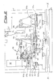
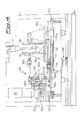
- the machine comprises a support frame 1 which has, constrained thereto, the means 2 for extrusion of the tube 3 of plastic material, the means 100 for moving the mould 4 in the longitudinal direction X-X, the means 200 for moving the mould 4 in the transverse direction Y-Y, the blowing nozzles 5 and the means 6 for removal of the moulded containers 3a.
- Said mould 4 is formed by two half-moulds 4a,4b symmetrically arranged with respect to a fixed reference axis of symmetry Z-Z.
- said means 100 for performing movement in the longitudinal direction comprise an electric motor 101 which is arranged parallel to the axis Z-Z and the shaft 101a of which carries a gear 101b suitable for engagement with a corresponding toothed wheel 102b mounted on a shaped sleeve 102 in turn arranged parallel to the axis Z-Z.
- the sleeve 102 has suitable opposite and externally open seats 102a which receive internally respective spindles 103 having, mounted at their free end, the small end of a respective connecting rod 104a,104b, the big end of which is pivotably mounted on one end of a respective rod 105a,105b.
- the lower rod 105a is connected to the carriage 106b supporting the half-mould 4b and sliding on the said rail 107 by means of the arrangement, in between, of a device 110 for adjusting the distance of the two half-moulds with respect to the fixed axis of symmetry Z-Z.
- Said adjustment device 110 comprises a bracket 111 to which the other free end of the rod 105b is fastened; the bracket 111 is in turn connected to one end of a sleeve 112, the other end of which is constrained to the base of the carriage 106b of the half-mould 4b by means of a screw/internal thread coupling 112a.
- the sleeve 112 has passing through it a splined shaft 113 extending parallel to the longitudinal axis of the machine.
- the rear end of the splined shaft 113 is provided with a screw/internal thread coupling 122a connecting the splined shaft itself and a support 122 in turn joined to a slide 120 movable on longitudinal rails 121, which slide carries all of the part of the actuating assembly 100 formed by the kinematic chain comprising motor 101 and rods 105a,105b.
- the pitch of the front screw/internal thread coupling 122a is double the pitch of the rear screw/internal thread coupling 122a and the two couplings operate in the opposite sense to each other so as to ensure the correct relative displacement of the two carriages 106a,106b, as will appear more clearly below.
- a hexagonal member 113a is provided for actuation of the said shaft by suitable means (not shown).
- Said devices 200 for displacement of the moulding assembly in the transverse direction Y-Y consist of a motor-reducer unit 210, the shaft 210a of which supports the small end of a connecting rod 211, the big end of which is pivotably mounted on the first end of a rod 212, the other end of which is pivotably mounted on the mould-support assembly.
- the rod 212 is interrupted and its continuity is ensured by a sleeved joint 213, the ends of which are coupled to the respective rod portions 212 by means of a screw/internal thread coupling operating in the opposite sense.
- the connecting rods, the rods, the splined shafts and the associated accessories may be duplicated so as to ensure an improved alignment and supporting and actuating capacity using elements which, although greater in number, may nevertheless be made with smaller dimensions which comply with normal production standards.
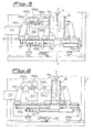
- Figures 5 and 6 show a second embodiment of the machine according to the invention, in which the actuating motor 1101 is arranged with its axis horizontal and operates a reducer 1102, the horizontal shaft of which supports a flat member 1102a to which two pins 1102b arranged at 180° with respect to each other are constrained.
- One end of a connecting rod 1104a, 1104b is pivotably mounted on each pin 1102b, the other end thereof being respectively joined to:
Landscapes
- Engineering & Computer Science (AREA)
- Manufacturing & Machinery (AREA)
- Mechanical Engineering (AREA)
- Blow-Moulding Or Thermoforming Of Plastics Or The Like (AREA)
- Moulds For Moulding Plastics Or The Like (AREA)
- Processing And Handling Of Plastics And Other Materials For Molding In General (AREA)
- Table Devices Or Equipment (AREA)
Abstract
Description
- with the machine stopped and depending on the
thickness of the mould 4 in the longitudinal direction,
the front
hexagonal member 113a is operated, rotating it in either direction in order to determine:
- both rotation of the front coupling 112a in one
direction or the other with consequent displacement of
the
carriage 106b away from/towards the axis Z-Z; - and rotation, in the opposite direction and with a
halved pitch, of the
rear coupling 122a so as to cause displacement of theslide 120 and therefore thecarriage 106a by an identical amount towards/away from said axis Z-Z;
- in a co-ordinated and controlled sequence by suitable programming and control means 1000;
- the
motor 101 is actuated (Figs. 1,2) so as to cause a rotation of the upper connectingrod 104a and the lower connectingrod 104b, such that thecarriage 106a and thecarriage 106b are respectively pushed and pulled away symmetrically from the axis Z-Z so as to cause opening of the two half-moulds - the entire mould-carrying assembly 4 is positioned
underneath the extruded
tubes 3 of plastic material by means of the actuating means 200; - the
motor 101 is operated in the opposite direction to the previous direction so as to cause counter-rotation of the two connectingrods carriage 106a and thecarriage 106b are respectively pushed and pulled towards the axis of symmetry Z-Z in order to cause closing of the two half-moulds tubes 3; - the
devices 200 for performing displacement in the transverse direction Y-Y are actuated so as to cause displacement of the said assembly underneath the blowing station 5 where moulding of the containers is performed; - the actuating
assembly 100 is actuated again in the longitudinal direction so as to cause opening of the two half-moulds
- the
rod 105a connected to one 4a of the two half-moulds - a
column 1100 for transmission to arod 105b connected to the other 4b of the two half-moulds
Claims (19)
- Machine for moulding containers (3a) made of plastic material, comprising an assembly (2) for extruding tubes (3) of plastic material, a blowing assembly (5), a mould for containing containers (3a), formed by two half-moulds (4a,4b) movable upon actuation of associated first means (100), in a longitudinal direction (X-X) and symmetrically with respect to a fixed axis (Z-Z) perpendicular to said longitudinal direction, the assembly formed by the mould (4) and the associated first actuating means (100) being movable, upon actuation of second actuating means (200), in a transverse direction (Y-Y) from a position corresponding to the extrusion assembly to a position corresponding to the blowing assembly and vice versa, characterized in that said first means for actuation of the half-moulds (4a,4b) in the longitudinal direction are of the electric type and means (110) for symmetrically adjusting the distance of the two half-moulds (4a,4b) from said fixed axis (Z-Z) are provided.
- Machine according to Claim 1, characterized in that said first means (100) for moving the two half-moulds consist of an electric motor (101), the shaft (101) of which is joined to a transmission assembly connected to associated carriages (6a,6b) carrying the two half-moulds.
- Machine according to Claim 2, characterized in that said transmission assembly comprises at least two rods (105a,105b) connected respectively to the said carriages (106a,106b) and to respective connecting rods (104a,104b;1104a,1104b).
- Machine according to Claim 3, characterized in that said connecting rods (104a,104b;1104a,1104b) are located opposite each other in the longitudinal direction (X-X).
- Machine according to Claim 4, characterized in that said connecting rods (104a,104b) have an axis of rotation parallel to the axis of symmetry (Z-Z) and are actuated by a gear (103) on which they are pivotably mounted and which is moved rotationally moved by the said drive shaft (101a).
- Machine according to Claim 3, characterized in that said connecting rods (1104a,1104b) are actuated by a flat member (1102a) joined to the shaft of a reducer (1102).
- Machine according to Claim 6, characterized in that said flat member (1102a) rotates about a horizontal axis.
- Machine according to Claim 6, characterized in that said motor (1101) actuating the reducer (1102) has an axis parallel to the direction (X-X) of displacement of the two half-moulds (4a,4b).
- Machine according to Claim 2, characterized in that said first actuating means (100) are mounted on a slide (120) movable in the longitudinal direction on associated fixed rails (121).
- Machine according to Claim 9, characterized in that said means (110) for adjusting the relative distance of the two half-moulds (4a,4b) are arranged in between said slide (120) and the front carriage (106b).
- Machine according to Claim 1, characterized in that said means (110) for adjusting the relative distance of the two half-moulds (4a,4b) comprise a sleeve (112) which is parallel to the longitudinal direction (X-X) and a first end of which is joined to the rod (105b) actuating the front carriage (106b) and the other end of which is constrained to the base of the said carriage (106b) by means of a screw/internal thread coupling (112a).
- Machine according to Claim 11, characterized in that said sleeve (112) has, passing through it, a splined shaft (113) extending parallel to the longitudinal axis of the machine.
- Machine according to Claim 12, characterized in that a screw/internal thread coupling (122a) is provided at the rear end of the splined shaft (112), between the said splined shaft and a support (122) in turn joined to said slide.
- Machine according to Claim 13, characterized in that the pitch of the front screw/internal thread coupling (122a) is double the pitch of the rear screw/internal thread coupling (122a) and the two couplings operate in the opposite sense to each other.
- Machine according to Claim 12, characterized in that the front end of the splined shaft (113) is provided with a hexagonal member (113a) for actuation of the said shaft.
- Machine according to Claim 1, characterized in that said second means (200) for actuating the moulding assembly (4) in the transverse direction are of the electric type.
- Machine according to Claim 16, characterized in that said second means (200) for actuating the mould (4) in the transverse direction consist of a motor reducer unit (210,210a) connected to a movement transmission assembly.
- Machine according to Claim 17, characterized in that said transmission assembly comprises a connecting rod (211), the small end of which is pivotably mounted on the shaft (210a) of the reducer and the big end of which is pivotably mounted on the first end of a rod (212), the other end of which is pivotably mounted on the mould-support assembly.
- Machine according to Claim 18, characterized in that the rod (212) is interrupted and its continuity is restored by means of a sleeved joint (213), the ends of which of which are coupled to the respective rod portions (212) by means of a screw/internal thread coupling operating in the opposite sense.
Applications Claiming Priority (2)
| Application Number | Priority Date | Filing Date | Title |
|---|---|---|---|
| ITMI20012230 | 2001-10-24 | ||
| IT2001MI002230A ITMI20012230A1 (en) | 2001-10-24 | 2001-10-24 | BLOWER FORMING MACHINE FOR PLASTIC CONTAINERS EQUIPPED WITH ELECTRIC TYPE DRIVE DEVICES |
Publications (3)
| Publication Number | Publication Date |
|---|---|
| EP1306193A2 true EP1306193A2 (en) | 2003-05-02 |
| EP1306193A3 EP1306193A3 (en) | 2003-10-15 |
| EP1306193B1 EP1306193B1 (en) | 2008-12-31 |
Family
ID=11448539
Family Applications (1)
| Application Number | Title | Priority Date | Filing Date |
|---|---|---|---|
| EP02079099A Expired - Lifetime EP1306193B1 (en) | 2001-10-24 | 2002-10-02 | Machine for blow-moulding containers made of plastic material, with actuating devices of the electric type |
Country Status (12)
| Country | Link |
|---|---|
| US (1) | US6884059B2 (en) |
| EP (1) | EP1306193B1 (en) |
| JP (1) | JP2003159740A (en) |
| AT (1) | ATE419106T1 (en) |
| AU (1) | AU2002301179B2 (en) |
| BR (1) | BR0203872B1 (en) |
| DE (1) | DE60230574D1 (en) |
| DK (1) | DK1306193T3 (en) |
| ES (1) | ES2319391T3 (en) |
| IT (1) | ITMI20012230A1 (en) |
| NZ (1) | NZ521537A (en) |
| PT (1) | PT1306193E (en) |
Cited By (7)
| Publication number | Priority date | Publication date | Assignee | Title |
|---|---|---|---|---|
| WO2006134031A1 (en) * | 2005-06-14 | 2006-12-21 | Techne Technipack Engineering Italia S.P.A. | Apparatus and method for closing of moulds |
| EP1818158A2 (en) | 2006-02-13 | 2007-08-15 | Magic MP S.p.A. | Machine for moulding plastic containers with linear-rack means for moving the mould-carrying unit |
| EP1914061A2 (en) | 2006-10-16 | 2008-04-23 | Magic MP S.p.A. | Machine for moulding plastic containers using means for moving mould-support unit comprising two in-line connecting tools |
| ITUA20163867A1 (en) * | 2016-05-27 | 2016-08-27 | Cristian Andreon | COMPACT AND QUICK PRESS FOR IRONING AND BLOWING PROCESSES |
| IT201700035363A1 (en) * | 2017-03-30 | 2018-09-30 | Lanfranchi Srl | DEVICE FOR THE PRODUCTION OF PLASTIC CONTAINERS |
| WO2019108577A1 (en) | 2017-11-28 | 2019-06-06 | Weiler Engineering, Inc. | Blow molding apparatus |
| EP4344852A1 (en) * | 2022-09-30 | 2024-04-03 | BEKUM Maschinenfabriken GmbH | Apparatus for manufacturing hollow bodies |
Families Citing this family (6)
| Publication number | Priority date | Publication date | Assignee | Title |
|---|---|---|---|---|
| ITMI20040835A1 (en) * | 2004-04-27 | 2004-07-27 | Magic Mp Spa | MACHINE FOR FORMING PLASTIC CONTAINERS WITH LINEAR MOTOR FOR HANDLING OF THE MOLD HOLDER GROUP |
| DE102004026450B4 (en) * | 2004-05-29 | 2007-10-25 | Krauss Maffei Gmbh | Clamping unit with double crank drive |
| US20080233229A1 (en) * | 2007-03-22 | 2008-09-25 | The Procter & Gamble Company | Apparatus and method for producing containers |
| EP2263854B1 (en) * | 2008-12-19 | 2013-05-01 | Krones AG | Electrically operated blow-moulding machine and the method |
| ITMI20131557A1 (en) * | 2013-09-20 | 2015-03-21 | Magic Mp Spa | MACHINE FOR THE CONSTRUCTION OF CONTAINERS IN THERMOPLASTIC MATERIAL |
| AU2016284878B2 (en) * | 2015-06-26 | 2019-10-03 | Shinwoo Costec Co., Ltd | Container manufacturing apparatus |
Family Cites Families (12)
| Publication number | Priority date | Publication date | Assignee | Title |
|---|---|---|---|---|
| DE2030488A1 (en) * | 1969-01-10 | 1972-01-05 | Mehnert J | Device for the production of hollow bodies made of thermoplastic material |
| US3883286A (en) * | 1972-03-08 | 1975-05-13 | Ethyl Dev Corp | Blow molding method and apparatus |
| US4421472A (en) * | 1981-08-31 | 1983-12-20 | R & B Machine Tool Company | Clamp for blow molding machine |
| DE4032659A1 (en) * | 1990-10-15 | 1992-04-16 | Kautex Maschinenbau Gmbh | METHOD AND DEVICE FOR PRODUCING HOLLOW BODIES FROM THERMOPLASTIC PLASTIC |
| JP2561776B2 (en) | 1992-06-17 | 1996-12-11 | 株式会社日本製鋼所 | Clamping device for blow molding machine |
| DE4223314A1 (en) | 1992-07-13 | 1994-01-20 | Gonzalez Augusto E Salvo | Opening and closing mechanism for blow mould tools - has mould clamping plates with extensions mounted on columns and spindles which have specific type drive for precise linear movements |
| US5478229A (en) * | 1993-01-29 | 1995-12-26 | The Japan Steel Works, Ltd. | Apparatus for forming hollow article |
| JP2988809B2 (en) * | 1993-07-21 | 1999-12-13 | 株式会社タハラ | Mold clamping device for blow molding machine |
| US6499988B1 (en) * | 1997-02-25 | 2002-12-31 | Kao Corporation | Blow molding machine |
| EP0913245A4 (en) * | 1997-02-25 | 2002-07-10 | Kao Corp | CLAMPING DEVICE FOR BLOWING MACHINES |
| JP3914632B2 (en) * | 1998-04-02 | 2007-05-16 | 株式会社タハラ | Hollow molding machine |
| DE19927138C2 (en) | 1999-06-15 | 2002-02-28 | Fischer W Mueller Blasformtech | Method and device for closing and opening the molds of a plastic processing machine |
-
2001
- 2001-10-24 IT IT2001MI002230A patent/ITMI20012230A1/en unknown
-
2002
- 2002-09-23 NZ NZ521537A patent/NZ521537A/en not_active IP Right Cessation
- 2002-09-24 BR BRPI0203872-2A patent/BR0203872B1/en not_active IP Right Cessation
- 2002-09-24 AU AU2002301179A patent/AU2002301179B2/en not_active Ceased
- 2002-10-02 ES ES02079099T patent/ES2319391T3/en not_active Expired - Lifetime
- 2002-10-02 EP EP02079099A patent/EP1306193B1/en not_active Expired - Lifetime
- 2002-10-02 US US10/262,917 patent/US6884059B2/en not_active Expired - Fee Related
- 2002-10-02 DK DK02079099T patent/DK1306193T3/en active
- 2002-10-02 PT PT02079099T patent/PT1306193E/en unknown
- 2002-10-02 DE DE60230574T patent/DE60230574D1/en not_active Expired - Lifetime
- 2002-10-02 AT AT02079099T patent/ATE419106T1/en not_active IP Right Cessation
- 2002-10-24 JP JP2002309462A patent/JP2003159740A/en active Pending
Cited By (13)
| Publication number | Priority date | Publication date | Assignee | Title |
|---|---|---|---|---|
| WO2006134031A1 (en) * | 2005-06-14 | 2006-12-21 | Techne Technipack Engineering Italia S.P.A. | Apparatus and method for closing of moulds |
| EP1818158A2 (en) | 2006-02-13 | 2007-08-15 | Magic MP S.p.A. | Machine for moulding plastic containers with linear-rack means for moving the mould-carrying unit |
| EP1818158A3 (en) * | 2006-02-13 | 2008-11-05 | Magic MP S.p.A. | Machine for moulding plastic containers with linear-rack means for moving the mould-carrying unit |
| EP1914061A2 (en) | 2006-10-16 | 2008-04-23 | Magic MP S.p.A. | Machine for moulding plastic containers using means for moving mould-support unit comprising two in-line connecting tools |
| EP1914061A3 (en) * | 2006-10-16 | 2010-08-11 | Magic MP S.p.A. | Machine for moulding plastic containers using means for moving mould-support unit comprising two in-line connecting tools |
| US7874828B2 (en) | 2006-10-16 | 2011-01-25 | Magic Mp S.P.A. | Machine for moulding plastic containers using means for moving the mould-support unit comprising two in-line connecting rods |
| ITUA20163867A1 (en) * | 2016-05-27 | 2016-08-27 | Cristian Andreon | COMPACT AND QUICK PRESS FOR IRONING AND BLOWING PROCESSES |
| IT201700035363A1 (en) * | 2017-03-30 | 2018-09-30 | Lanfranchi Srl | DEVICE FOR THE PRODUCTION OF PLASTIC CONTAINERS |
| WO2018178774A3 (en) * | 2017-03-30 | 2018-12-06 | Lanfranchi S.R.L. | Device for the production of plastic containers |
| WO2019108577A1 (en) | 2017-11-28 | 2019-06-06 | Weiler Engineering, Inc. | Blow molding apparatus |
| EP3717199A4 (en) * | 2017-11-28 | 2021-08-04 | Weiler Engineering, Inc. | BLOW MOLDING APPARATUS |
| EP4344852A1 (en) * | 2022-09-30 | 2024-04-03 | BEKUM Maschinenfabriken GmbH | Apparatus for manufacturing hollow bodies |
| WO2024068807A1 (en) * | 2022-09-30 | 2024-04-04 | Bekum Maschinenfabriken Gmbh | Device for producing hollow bodies |
Also Published As
| Publication number | Publication date |
|---|---|
| ES2319391T3 (en) | 2009-05-07 |
| AU2002301179B2 (en) | 2007-10-04 |
| ATE419106T1 (en) | 2009-01-15 |
| JP2003159740A (en) | 2003-06-03 |
| DE60230574D1 (en) | 2009-02-12 |
| EP1306193A3 (en) | 2003-10-15 |
| BR0203872A (en) | 2003-07-15 |
| US6884059B2 (en) | 2005-04-26 |
| EP1306193B1 (en) | 2008-12-31 |
| NZ521537A (en) | 2004-06-25 |
| DK1306193T3 (en) | 2009-03-16 |
| ITMI20012230A1 (en) | 2003-04-24 |
| BR0203872B1 (en) | 2010-11-16 |
| US20030077352A1 (en) | 2003-04-24 |
| PT1306193E (en) | 2009-02-25 |
Similar Documents
| Publication | Publication Date | Title |
|---|---|---|
| EP1306193B1 (en) | Machine for blow-moulding containers made of plastic material, with actuating devices of the electric type | |
| JP4112658B2 (en) | Blow molding machine | |
| RU2481948C2 (en) | Device for moring reservoirs from synthetic material by blowing | |
| EP1626903B1 (en) | Device for blow moulding, filling and closing plastic containers | |
| US3355763A (en) | Rotary parison head blow molding machine | |
| BRPI0811255B1 (en) | apparatus for opening and closing mold arms in a glass artifact forming machine | |
| JP2002503604A (en) | Transfer device for hollow body with neck | |
| JPH01105724A (en) | Rotary molder | |
| US5464635A (en) | Blow molding machine | |
| US4648831A (en) | Blow molding apparatus | |
| CN107297884B (en) | Blow mold opening and closing device and blow molding machine | |
| EP1591226A1 (en) | Machine for forming plastic containers with a linear motor for moving the mould-support unit | |
| US4569651A (en) | Blow molding apparatus | |
| AU773060B2 (en) | I.S. machine | |
| EP1818158B1 (en) | Machine for moulding plastic containers with linear-rack means for moving the mould-carrying unit | |
| EP1588824B1 (en) | Device for adjusting the thickness of the extruded parison in a blow molding machine | |
| CN115042397B (en) | Injection mold | |
| RU2096176C1 (en) | Device for manufacturing hollow articles made of thermoplast | |
| KR0115664Y1 (en) | Mold switchgear of blow molding machine | |
| CN116766561B (en) | Plastic container blow molding device | |
| US20260084364A1 (en) | Apparatus | |
| JPH0651345B2 (en) | Parison cutting device for blow molding machine | |
| JP4718280B2 (en) | Method for aligning axial center of driving nozzle in hollow molding apparatus | |
| CN116252456A (en) | Injection and blowing integrated production line for plastic cups with external expansion in the middle | |
| DE19519094A1 (en) | Blow moulding of long hollow plastic products and blow moulding plant |
Legal Events
| Date | Code | Title | Description |
|---|---|---|---|
| PUAI | Public reference made under article 153(3) epc to a published international application that has entered the european phase |
Free format text: ORIGINAL CODE: 0009012 |
|
| AK | Designated contracting states |
Designated state(s): AT BE BG CH CY CZ DE DK EE ES FI FR GB GR IE IT LI LU MC NL PT SE SK TR |
|
| AX | Request for extension of the european patent |
Extension state: AL LT LV MK RO SI |
|
| PUAL | Search report despatched |
Free format text: ORIGINAL CODE: 0009013 |
|
| AK | Designated contracting states |
Kind code of ref document: A3 Designated state(s): AT BE BG CH CY CZ DE DK EE ES FI FR GB GR IE IT LI LU MC NL PT SE SK TR |
|
| AX | Request for extension of the european patent |
Extension state: AL LT LV MK RO SI |
|
| 17P | Request for examination filed |
Effective date: 20040405 |
|
| 17Q | First examination report despatched |
Effective date: 20040430 |
|
| AKX | Designation fees paid |
Designated state(s): AT BE BG CH CY CZ DE DK EE ES FI FR GB GR IE IT LI LU MC NL PT SE SK TR |
|
| 17Q | First examination report despatched |
Effective date: 20040430 |
|
| GRAP | Despatch of communication of intention to grant a patent |
Free format text: ORIGINAL CODE: EPIDOSNIGR1 |
|
| GRAS | Grant fee paid |
Free format text: ORIGINAL CODE: EPIDOSNIGR3 |
|
| GRAA | (expected) grant |
Free format text: ORIGINAL CODE: 0009210 |
|
| AK | Designated contracting states |
Kind code of ref document: B1 Designated state(s): AT BE BG CH CY CZ DE DK EE ES FI FR GB GR IE IT LI LU MC NL PT SE SK TR |
|
| REG | Reference to a national code |
Ref country code: CH Ref legal event code: EP Ref country code: GB Ref legal event code: FG4D |
|
| REG | Reference to a national code |
Ref country code: CH Ref legal event code: NV Representative=s name: DR. LUSUARDI AG |
|
| REF | Corresponds to: |
Ref document number: 60230574 Country of ref document: DE Date of ref document: 20090212 Kind code of ref document: P |
|
| REG | Reference to a national code |
Ref country code: IE Ref legal event code: FG4D |
|
| REG | Reference to a national code |
Ref country code: PT Ref legal event code: SC4A Free format text: AVAILABILITY OF NATIONAL TRANSLATION Effective date: 20090216 |
|
| REG | Reference to a national code |
Ref country code: DK Ref legal event code: T3 |
|
| REG | Reference to a national code |
Ref country code: GR Ref legal event code: EP Ref document number: 20090400787 Country of ref document: GR |
|
| REG | Reference to a national code |
Ref country code: SE Ref legal event code: TRGR |
|
| REG | Reference to a national code |
Ref country code: ES Ref legal event code: FG2A Ref document number: 2319391 Country of ref document: ES Kind code of ref document: T3 |
|
| PG25 | Lapsed in a contracting state [announced via postgrant information from national office to epo] |
Ref country code: BE Free format text: LAPSE BECAUSE OF FAILURE TO SUBMIT A TRANSLATION OF THE DESCRIPTION OR TO PAY THE FEE WITHIN THE PRESCRIBED TIME-LIMIT Effective date: 20081231 Ref country code: EE Free format text: LAPSE BECAUSE OF FAILURE TO SUBMIT A TRANSLATION OF THE DESCRIPTION OR TO PAY THE FEE WITHIN THE PRESCRIBED TIME-LIMIT Effective date: 20081231 |
|
| PG25 | Lapsed in a contracting state [announced via postgrant information from national office to epo] |
Ref country code: AT Free format text: LAPSE BECAUSE OF FAILURE TO SUBMIT A TRANSLATION OF THE DESCRIPTION OR TO PAY THE FEE WITHIN THE PRESCRIBED TIME-LIMIT Effective date: 20081231 Ref country code: CZ Free format text: LAPSE BECAUSE OF FAILURE TO SUBMIT A TRANSLATION OF THE DESCRIPTION OR TO PAY THE FEE WITHIN THE PRESCRIBED TIME-LIMIT Effective date: 20081231 |
|
| PLBE | No opposition filed within time limit |
Free format text: ORIGINAL CODE: 0009261 |
|
| STAA | Information on the status of an ep patent application or granted ep patent |
Free format text: STATUS: NO OPPOSITION FILED WITHIN TIME LIMIT |
|
| 26N | No opposition filed |
Effective date: 20091001 |
|
| PG25 | Lapsed in a contracting state [announced via postgrant information from national office to epo] |
Ref country code: BG Free format text: LAPSE BECAUSE OF FAILURE TO SUBMIT A TRANSLATION OF THE DESCRIPTION OR TO PAY THE FEE WITHIN THE PRESCRIBED TIME-LIMIT Effective date: 20090331 |
|
| PG25 | Lapsed in a contracting state [announced via postgrant information from national office to epo] |
Ref country code: MC Free format text: LAPSE BECAUSE OF NON-PAYMENT OF DUE FEES Effective date: 20091031 |
|
| PG25 | Lapsed in a contracting state [announced via postgrant information from national office to epo] |
Ref country code: IE Free format text: LAPSE BECAUSE OF NON-PAYMENT OF DUE FEES Effective date: 20091002 |
|
| PGFP | Annual fee paid to national office [announced via postgrant information from national office to epo] |
Ref country code: TR Payment date: 20100930 Year of fee payment: 9 |
|
| PGFP | Annual fee paid to national office [announced via postgrant information from national office to epo] |
Ref country code: DK Payment date: 20101015 Year of fee payment: 9 Ref country code: FR Payment date: 20101112 Year of fee payment: 9 Ref country code: NL Payment date: 20101028 Year of fee payment: 9 |
|
| PGFP | Annual fee paid to national office [announced via postgrant information from national office to epo] |
Ref country code: CH Payment date: 20100930 Year of fee payment: 9 Ref country code: DE Payment date: 20101025 Year of fee payment: 9 Ref country code: FI Payment date: 20101022 Year of fee payment: 9 Ref country code: PT Payment date: 20100930 Year of fee payment: 9 Ref country code: SK Payment date: 20101001 Year of fee payment: 9 |
|
| PGFP | Annual fee paid to national office [announced via postgrant information from national office to epo] |
Ref country code: GR Payment date: 20101101 Year of fee payment: 9 Ref country code: GB Payment date: 20101027 Year of fee payment: 9 Ref country code: IT Payment date: 20101028 Year of fee payment: 9 Ref country code: SE Payment date: 20101021 Year of fee payment: 9 |
|
| PG25 | Lapsed in a contracting state [announced via postgrant information from national office to epo] |
Ref country code: LU Free format text: LAPSE BECAUSE OF NON-PAYMENT OF DUE FEES Effective date: 20091002 |
|
| PGFP | Annual fee paid to national office [announced via postgrant information from national office to epo] |
Ref country code: ES Payment date: 20100930 Year of fee payment: 9 |
|
| PG25 | Lapsed in a contracting state [announced via postgrant information from national office to epo] |
Ref country code: CY Free format text: LAPSE BECAUSE OF FAILURE TO SUBMIT A TRANSLATION OF THE DESCRIPTION OR TO PAY THE FEE WITHIN THE PRESCRIBED TIME-LIMIT Effective date: 20081231 |
|
| REG | Reference to a national code |
Ref country code: PT Ref legal event code: MM4A Free format text: LAPSE DUE TO NON-PAYMENT OF FEES Effective date: 20120402 |
|
| REG | Reference to a national code |
Ref country code: NL Ref legal event code: V1 Effective date: 20120501 |
|
| REG | Reference to a national code |
Ref country code: CH Ref legal event code: PL |
|
| REG | Reference to a national code |
Ref country code: GR Ref legal event code: ML Ref document number: 20090400787 Country of ref document: GR Effective date: 20120503 |
|
| GBPC | Gb: european patent ceased through non-payment of renewal fee |
Effective date: 20111002 |
|
| REG | Reference to a national code |
Ref country code: DK Ref legal event code: EBP |
|
| REG | Reference to a national code |
Ref country code: SE Ref legal event code: EUG Ref country code: SK Ref legal event code: MM4A Ref document number: E 5155 Country of ref document: SK Effective date: 20111002 |
|
| REG | Reference to a national code |
Ref country code: FR Ref legal event code: ST Effective date: 20120629 |
|
| PG25 | Lapsed in a contracting state [announced via postgrant information from national office to epo] |
Ref country code: NL Free format text: LAPSE BECAUSE OF NON-PAYMENT OF DUE FEES Effective date: 20120501 Ref country code: LI Free format text: LAPSE BECAUSE OF NON-PAYMENT OF DUE FEES Effective date: 20111031 Ref country code: SK Free format text: LAPSE BECAUSE OF NON-PAYMENT OF DUE FEES Effective date: 20111002 Ref country code: CH Free format text: LAPSE BECAUSE OF NON-PAYMENT OF DUE FEES Effective date: 20111031 Ref country code: DE Free format text: LAPSE BECAUSE OF NON-PAYMENT OF DUE FEES Effective date: 20120501 |
|
| REG | Reference to a national code |
Ref country code: DE Ref legal event code: R119 Ref document number: 60230574 Country of ref document: DE Effective date: 20120501 |
|
| PG25 | Lapsed in a contracting state [announced via postgrant information from national office to epo] |
Ref country code: GR Free format text: LAPSE BECAUSE OF NON-PAYMENT OF DUE FEES Effective date: 20120503 Ref country code: GB Free format text: LAPSE BECAUSE OF NON-PAYMENT OF DUE FEES Effective date: 20111002 Ref country code: FI Free format text: LAPSE BECAUSE OF NON-PAYMENT OF DUE FEES Effective date: 20111002 Ref country code: FR Free format text: LAPSE BECAUSE OF NON-PAYMENT OF DUE FEES Effective date: 20111102 Ref country code: IT Free format text: LAPSE BECAUSE OF NON-PAYMENT OF DUE FEES Effective date: 20111002 Ref country code: PT Free format text: LAPSE BECAUSE OF NON-PAYMENT OF DUE FEES Effective date: 20120402 |
|
| PG25 | Lapsed in a contracting state [announced via postgrant information from national office to epo] |
Ref country code: DK Free format text: LAPSE BECAUSE OF NON-PAYMENT OF DUE FEES Effective date: 20111031 Ref country code: SE Free format text: LAPSE BECAUSE OF NON-PAYMENT OF DUE FEES Effective date: 20111003 |
|
| REG | Reference to a national code |
Ref country code: ES Ref legal event code: FD2A Effective date: 20131023 |
|
| PG25 | Lapsed in a contracting state [announced via postgrant information from national office to epo] |
Ref country code: TR Free format text: LAPSE BECAUSE OF NON-PAYMENT OF DUE FEES Effective date: 20111002 |
|
| PG25 | Lapsed in a contracting state [announced via postgrant information from national office to epo] |
Ref country code: ES Free format text: LAPSE BECAUSE OF NON-PAYMENT OF DUE FEES Effective date: 20111003 |