EP1306239A2 - Unité d'alimentation d'air pour un véhicule - Google Patents
Unité d'alimentation d'air pour un véhicule Download PDFInfo
- Publication number
- EP1306239A2 EP1306239A2 EP02018423A EP02018423A EP1306239A2 EP 1306239 A2 EP1306239 A2 EP 1306239A2 EP 02018423 A EP02018423 A EP 02018423A EP 02018423 A EP02018423 A EP 02018423A EP 1306239 A2 EP1306239 A2 EP 1306239A2
- Authority
- EP
- European Patent Office
- Prior art keywords
- supply unit
- air supply
- air
- hose
- unit according
- Prior art date
- Legal status (The legal status is an assumption and is not a legal conclusion. Google has not performed a legal analysis and makes no representation as to the accuracy of the status listed.)
- Granted
Links
- 229920001971 elastomer Polymers 0.000 claims abstract description 7
- 239000005060 rubber Substances 0.000 claims abstract description 5
- 230000003584 silencer Effects 0.000 claims description 22
- 239000000463 material Substances 0.000 claims description 4
- 239000006096 absorbing agent Substances 0.000 abstract 1
- 229920000459 Nitrile rubber Polymers 0.000 description 3
- 230000000694 effects Effects 0.000 description 3
- NIXOWILDQLNWCW-UHFFFAOYSA-M Acrylate Chemical compound [O-]C(=O)C=C NIXOWILDQLNWCW-UHFFFAOYSA-M 0.000 description 2
- 238000013016 damping Methods 0.000 description 2
- 239000000806 elastomer Substances 0.000 description 2
- 238000009434 installation Methods 0.000 description 2
- 238000004519 manufacturing process Methods 0.000 description 2
- 239000004952 Polyamide Substances 0.000 description 1
- 230000002238 attenuated effect Effects 0.000 description 1
- 238000007599 discharging Methods 0.000 description 1
- 239000006260 foam Substances 0.000 description 1
- 238000001746 injection moulding Methods 0.000 description 1
- 238000000465 moulding Methods 0.000 description 1
- 239000004033 plastic Substances 0.000 description 1
- 229920002647 polyamide Polymers 0.000 description 1
- 230000000717 retained effect Effects 0.000 description 1
- 239000007779 soft material Substances 0.000 description 1
- 238000010025 steaming Methods 0.000 description 1
- 239000000725 suspension Substances 0.000 description 1
- 238000011144 upstream manufacturing Methods 0.000 description 1
- 238000013022 venting Methods 0.000 description 1
Images

Classifications
-
- B—PERFORMING OPERATIONS; TRANSPORTING
- B60—VEHICLES IN GENERAL
- B60G—VEHICLE SUSPENSION ARRANGEMENTS
- B60G17/00—Resilient suspensions having means for adjusting the spring or vibration-damper characteristics, for regulating the distance between a supporting surface and a sprung part of vehicle or for locking suspension during use to meet varying vehicular or surface conditions, e.g. due to speed or load
- B60G17/02—Spring characteristics, e.g. mechanical springs and mechanical adjusting means
- B60G17/04—Spring characteristics, e.g. mechanical springs and mechanical adjusting means fluid spring characteristics
- B60G17/0408—Spring characteristics, e.g. mechanical springs and mechanical adjusting means fluid spring characteristics details, e.g. antifreeze for suspension fluid, pumps, retarding means per se
-
- B—PERFORMING OPERATIONS; TRANSPORTING
- B60—VEHICLES IN GENERAL
- B60G—VEHICLE SUSPENSION ARRANGEMENTS
- B60G17/00—Resilient suspensions having means for adjusting the spring or vibration-damper characteristics, for regulating the distance between a supporting surface and a sprung part of vehicle or for locking suspension during use to meet varying vehicular or surface conditions, e.g. due to speed or load
- B60G17/02—Spring characteristics, e.g. mechanical springs and mechanical adjusting means
- B60G17/04—Spring characteristics, e.g. mechanical springs and mechanical adjusting means fluid spring characteristics
- B60G17/052—Pneumatic spring characteristics
- B60G17/0523—Regulating distributors or valves for pneumatic springs
-
- B—PERFORMING OPERATIONS; TRANSPORTING
- B60—VEHICLES IN GENERAL
- B60G—VEHICLE SUSPENSION ARRANGEMENTS
- B60G2500/00—Indexing codes relating to the regulated action or device
- B60G2500/20—Spring action or springs
- B60G2500/201—Air spring system type
- B60G2500/2012—Open systems
Definitions
- the invention relates to an air supply unit for a vehicle with pneumatic Facilities, esp. With air springs, a compressor and a silencer contains.
- the silencer has a plurality of chambers arranged one behind the other, the diffuser-like narrowing channels are interconnected. Furthermore are porous plates e.g. made of sintered material with a variety of fine channels, through the air is passed through. With this air supply unit could already a significant sound reduction can be achieved.
- the muffler however, has the disadvantage that he needs a certain minimum diameter and a minimum length. at Many modern vehicles, the installation space is so cramped that the muffler difficult to accommodate due to its volume. In addition, the production of the Muffler consuming because it has a complicated structure in its interior and composed of a plurality of individual parts, such as the diffusers.
- the invention is therefore based on the object, an air supply unit of to provide the aforementioned type, which has a muffler, the can be installed in very tight conditions in the vehicle and on simple Way can be produced.
- This object is achieved in that the muffler from a or more hoses made of rubber or a rubber-like material, and is divided into several chambers by throttling in its interior.
- the silencer is an air discharge hose that does not require a separate housing.
- the space problem that always exists with damping measures is thus overcome.
- the hose has a smaller diameter than known silencers. by virtue of Its flexibility means that it can be routed practically anywhere in the vehicle. Consequently the muffler can be arranged in the vehicle even under unfavorable circumstances.
- the silencer is made up of very simple parts. Both its production as Its installation on the air supply unit are possible in a simple manner. It can also be used on standard, commercially available components.
- the hose can e.g. be produced by injection molding, wherein by inserting a correspondingly shaped core, the throttle bodies integrally into the hose can be molded.
- This embodiment of the invention is then advantageous if the silencer is to be produced in large numbers.
- the silencer is made in one piece, additional steps, such as the assembly of Individual parts, can be omitted.
- the muffler is composed of several tube sections, the are interconnected by connecting pieces, wherein the connecting pieces additionally assume the function of throttle points.
- This embodiment of the Invention is particularly advantageous when the muffler only in minor Quantity required as standard, non-specialized items are used can.
- the air supply unit according to the invention could by the muffler a reduction of the exhaust noise, but also the intake noise and knocking noises of the compressor can be achieved by at least 7 dBA.
- the soundproofing is caused on the one hand by the throttle points, where the sound energy especially at the short-term, very intense air flow when deflating the system is swirled and converted into heat.
- the soft material of the Steaming hose could in Compared to the above-mentioned known air supply unit, the one from hard components existing silencer, not only a better noise reduction be achieved, but the remaining noise is also more pleasant and less hard.
- a high quality of noise reduction can be achieved by suitable Properties of the hose material can be achieved. It has been shown that one Particularly good damping could be achieved if the hose has a Shore hardness between 70 and 80, preferably about 75 (indicated in Shore A).
- the third significant effect for reducing the sound effect in the invention Reflections in the chambers, which leads to an extinguishing of the sound phase-shifted, reflected sound waves of the same frequency lead.
- the Chambers designed so that their lengths in an integer ratio to the Wavelength of those portions of the sound are to be attenuated priority.
- the muffler can thus be optimized by choosing suitable dimensions, however, these dimensions depend on the noise to be damped and thus from the other components of the air supply unit, in particular the compressor, are.
- a strong reduction of low frequencies up to about 1000 Hz
- the muffler is made a hose in which the chambers are arranged one behind the other, so that they are separated from the Air can be flowed through in order.
- Such an embodiment of Invention has the advantage of being particularly simple and a particularly slim Have silencers.
- the silencer on its middle section two or more parallel hoses.
- These Embodiment has the advantage of a particularly short, compact design.
- the air flow is divided into parallel streams and after merged again for a certain distance.
- the sound waves spread in the parallel hoses and overlap each other in the places where they again be merged, whereby it is for the cancellation of phase-shifted Sound waves of the same frequency comes.
- this muffler are two or more Chambers arranged parallel to each other, wherein the branching points also can be formed simultaneously as throttle points.
- This silencer is special good in the manner described above from several tube sections and Connectors produce, with the connectors branches exhibit.
- silencer with in-line and to combine with parallel chambers are also within the scope of the invention.
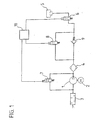
- Fig. 1 shows a level control system in a simplified representation.
- To the air supply unit include a compressor 1 that can be powered by a motor 2, as well as a silencer 3 and an air dryer 4.
- the pneumatic elements by The air supply unit to be supplied with air are air springs 5, from those in Fig. 1 for the sake of simplicity, only one is shown.
- the air springs 5 are upstream valves 6, via which the individual air springs 5 individually controlled can be.
- the valves 7, and 8 are actuated electromagnetically. You can go through an electronic control unit 10 are controlled.
- the venting or suction of air may e.g. for the level control of a vehicle with Serve air suspension.
- the compressor sucks 1 air from the environment via the silencer 3 and promotes them over the Air dryer 4 and the check valve 9 via the in-transit position Valves 6 to the air springs 5.
- the check valve 9 ensures that the air unhindered added to the system, but only controlled by the valve 8 again can be drained.
- the valves 6, 7 and 8 open. By the valve 7 is when draining in the air supply unit of the Bypassed compressor 1. The air then flows through the air dryer 4 and the Silencer 3 in the reverse direction and enters the outdoors.
- the system ensures that both the inflow of air to the system and the Discharge of air from the system is a sound attenuation.
- the air is always passed through the air dryer 4, where it is dried when flowing into the system and when flowing out of the system the retained moisture in the air dryer 4 is discharged to the outside.
- the muffler 3 will now be explained in more detail with reference to Figures 2 to 4.
- Silencer consists of individual cylindrical tube sections 11 made of rubber, z, B. made of NBR (acrylonitrile butadiene rubber) or ACM (acrylate elastomer) with a Shore hardness 75.
- the tube sections 11 are open at one end and provided at the other end with connectors 12, each to the free end towards a paragraph 13 having a reduced diameter, in the open End of the adjacent Schlauchabschittes 11 is inserted.
- the connecting pieces 12 are formed on the tube sections 11. Alternatively, they can be prepared separately and connected to the tube sections 11.
- the Connectors 12 are penetrated by holes 14, mainly in Longitudinal direction of the muffler and the diameter is significantly lower as the inner diameter of the tube sections 11, so that throttle points formed become.
- Participants give the tube sections 11 a hose that in his Inner has a plurality of chambers 15 which are arranged one behind the other and through the Throttle 14 are separated from each other.
- This hose is also at one end with a hose portion 16 is provided which has no connection piece 12, so that the Hose is open at both ends.
- the one end of the hose is with the Air supply unit connected while the other end leads into the open (Fig. 1), so that air taken in or discharged by the air supply unit passes through the hose is passed.
- the muffler of FIG. 3 is similar in its operation to that of Fig. 2. He is but not composed of individual sections, but consists of one single tube 17 made of rubber, the projections 18 at its inner diameter has, which form the throttle bodies 14 and merge integrally into the tube 17. In turn, chambers 15 are formed between the throttling points 14.
- a Silencer may e.g. by molding in a mold with a core for training the structures are made inside the tube 17.
- the chambers 15 can be about twice as long be as the throttle body 15 and the inner diameter of the tube 17 and the Hose sections 11 and 16 about twice as large as that of the throttle bodies 14th
- Typical dimensions for a model with three orifices were, for example: Total length 200 mm, length of the chambers 40 mm, diameter of the chambers 10 mm, Diameter of the throttling points 4.5 mm, wall thickness of the hose 2 mm.
- Fig. 4 In the embodiment shown in Fig. 4 are two tube sections 19 and 20 arranged parallel to each other. In their ends are connectors 21 and 22nd used. The connection of the silencer to the air supply unit as well as Exit to the outside via hose sections 23 and 24, which also on the Connecting pieces 21 and 22 are pushed. The connecting pieces 21 and 22 have channels for guiding the air, which branch at 26. The diameter of the Channels 25 is less than the inner diameter of the tube sections. The Connecting pieces 21 and 22 thus simultaneously act as throttling points.
- the Hose sections 19 and 20 thus form two chambers 27 and 28 which are parallel are arranged to each other.
- the tube sections 19, 20, 23 and 24 are made Gum, e.g. NBR or an acrylate elastomer.
- the connectors can be off Plastic, e.g. Made of polyamide.
- the air is in the muffler of the hose section 23 or 24 coming in the branches 26 in the Verbindugs Nativeen 21 and 22 in two parallel Divided flows that led in the tube sections 19 and 20 and in the second connector 22 and 21 is brought together again.
- the sound is spreading along the same paths.
- the sound is divided into two fronts that in the second connector 22 or 21 are superimposed and thereby partially cancel each other out.
Landscapes
- Engineering & Computer Science (AREA)
- Mechanical Engineering (AREA)
- Compressor (AREA)
- Exhaust Silencers (AREA)
- Structures Of Non-Positive Displacement Pumps (AREA)
Applications Claiming Priority (2)
| Application Number | Priority Date | Filing Date | Title |
|---|---|---|---|
| DE10152153A DE10152153C2 (de) | 2001-10-25 | 2001-10-25 | Schalldämpfer eines Luftversorgungs-Aggregats für ein Fahrzeug |
| DE10152153 | 2001-10-25 |
Publications (3)
| Publication Number | Publication Date |
|---|---|
| EP1306239A2 true EP1306239A2 (fr) | 2003-05-02 |
| EP1306239A3 EP1306239A3 (fr) | 2004-11-17 |
| EP1306239B1 EP1306239B1 (fr) | 2008-08-06 |
Family
ID=7703349
Family Applications (1)
| Application Number | Title | Priority Date | Filing Date |
|---|---|---|---|
| EP02018423A Expired - Lifetime EP1306239B1 (fr) | 2001-10-25 | 2002-08-16 | Unité d'alimentation d'air pour un véhicule |
Country Status (4)
| Country | Link |
|---|---|
| US (1) | US20030080481A1 (fr) |
| EP (1) | EP1306239B1 (fr) |
| JP (1) | JP2003148123A (fr) |
| DE (2) | DE10152153C2 (fr) |
Cited By (3)
| Publication number | Priority date | Publication date | Assignee | Title |
|---|---|---|---|---|
| WO2011160735A1 (fr) * | 2010-06-24 | 2011-12-29 | Wabco Gmbh | Dispositif d'alimentation en air pour un véhicule à moteur, pourvu d'appareils pneumatiques |
| EP1411244B1 (fr) | 2002-10-16 | 2015-09-09 | WABCO GmbH | Dispositif pour l'insonorisation d'un compresseur d'air |
| TWI727808B (zh) * | 2020-05-22 | 2021-05-11 | 林鈺文 | 空壓機之降噪裝置 |
Families Citing this family (4)
| Publication number | Priority date | Publication date | Assignee | Title |
|---|---|---|---|---|
| DE102010047402A1 (de) | 2010-10-02 | 2012-04-05 | Wabco Gmbh | Verdichter sowie ein Verfahren zum Betrieb eines solchen Verdichters |
| US20150275882A1 (en) * | 2012-09-25 | 2015-10-01 | Jaguar Land Rover Limited | Noise suppressor for vehicle suspension system |
| US20200362845A1 (en) * | 2019-05-14 | 2020-11-19 | Cummins Inc. | Resonance free compressor inlet acoustic suppressor |
| EP4100661A4 (fr) * | 2020-02-06 | 2024-03-27 | Bruce V. Weeks | Éléments d'absorption d'impact, systèmes et procédés d'utilisation |
Citations (2)
| Publication number | Priority date | Publication date | Assignee | Title |
|---|---|---|---|---|
| DE19835491A1 (de) | 1998-08-06 | 2000-02-17 | Continental Ag | Niveauregeleinrichtung für Fahrzeuge mit Luftfedern |
| DE10121582A1 (de) | 2001-05-03 | 2002-11-14 | Continental Ag | Luftversorgungs-Aggregat für Fahrzeuge mit einem Kompressor und einem Schalldämpfer |
Family Cites Families (17)
| Publication number | Priority date | Publication date | Assignee | Title |
|---|---|---|---|---|
| GB471431A (en) * | 1936-03-03 | 1937-09-03 | Frederick Heather | Improvements in and relating to silencers for gaseous currents |
| US2903085A (en) * | 1954-07-06 | 1959-09-08 | James L Matheny | Engine exhaust muffler |
| FR1272608A (fr) * | 1960-08-19 | 1961-09-29 | Polycarbure | Silencieux pour l'écoulement pulsatoire de gaz |
| US3187837A (en) * | 1963-08-28 | 1965-06-08 | Charles G Beeching | Free flow acoustic silencer constructed of resilient material |
| DE2134178A1 (de) * | 1971-03-03 | 1972-09-21 | VEB Monsator Haushaltgroßgeratekom binat Schwarzenberg, χ 9430 Schwarzen berg | Dampfer fur Verdichter, insbesondere fur hermetische Kältemittelverdichter |
| JPS528506A (en) * | 1975-07-09 | 1977-01-22 | Hitachi Ltd | All closed motor driven compressor |
| US4234054A (en) * | 1978-04-18 | 1980-11-18 | Chapin John S | Multi-duct muffler |
| US4239461A (en) * | 1978-11-06 | 1980-12-16 | Copeland Corporation | Compressor induction system |
| US4285534A (en) * | 1979-12-28 | 1981-08-25 | Nichirin Rubber Industrial Co., Ltd. | Pulsation-absorbing flexible pipe for pressure fluid device |
| US4448538A (en) * | 1982-04-06 | 1984-05-15 | Juval Mantel | Device for reducing static and dynamic pressures in pipelines, particularly of solid-borne sound in tubular conduits |
| DE3311682A1 (de) * | 1983-03-30 | 1984-10-04 | Knorr-Bremse GmbH, 8000 München | Luftrockner |
| US4915594A (en) * | 1986-04-25 | 1990-04-10 | Campbell Hausfeld/Scott Fetzer Company | Improved compressor crankshaft |
| GB9119534D0 (en) * | 1991-09-13 | 1991-10-23 | Dunlop Ltd | Vehicle suspension system |
| US5183974A (en) * | 1992-04-03 | 1993-02-02 | General Motors Corporation | Gas pulsation attenuator for automotive air conditioning compressor |
| FI94903C (fi) * | 1994-03-09 | 1995-11-10 | Neles Jamesbury Oy | Menetelmä kaasuvirtauksen kuristamisen aiheuttaman melun vaimentamiseksi ja kaasuvirtauskanavalla varustettu laite |
| US5435699A (en) * | 1994-04-05 | 1995-07-25 | Ford Motor Company | Accumulator for air conditioning system |
| WO1999051909A1 (fr) * | 1998-04-01 | 1999-10-14 | Aeroquip-Vickers International Gmbh | Systeme pour reduire les pulsations et/ou les vibrations dans des systemes hydrauliques de conduites en tuyaux souples |
-
2001
- 2001-10-25 DE DE10152153A patent/DE10152153C2/de not_active Expired - Fee Related
-
2002
- 2002-08-16 DE DE50212593T patent/DE50212593D1/de not_active Expired - Lifetime
- 2002-08-16 EP EP02018423A patent/EP1306239B1/fr not_active Expired - Lifetime
- 2002-09-26 JP JP2002280743A patent/JP2003148123A/ja not_active Withdrawn
- 2002-10-25 US US10/279,976 patent/US20030080481A1/en not_active Abandoned
Patent Citations (2)
| Publication number | Priority date | Publication date | Assignee | Title |
|---|---|---|---|---|
| DE19835491A1 (de) | 1998-08-06 | 2000-02-17 | Continental Ag | Niveauregeleinrichtung für Fahrzeuge mit Luftfedern |
| DE10121582A1 (de) | 2001-05-03 | 2002-11-14 | Continental Ag | Luftversorgungs-Aggregat für Fahrzeuge mit einem Kompressor und einem Schalldämpfer |
Cited By (6)
| Publication number | Priority date | Publication date | Assignee | Title |
|---|---|---|---|---|
| EP1411244B1 (fr) | 2002-10-16 | 2015-09-09 | WABCO GmbH | Dispositif pour l'insonorisation d'un compresseur d'air |
| WO2011160735A1 (fr) * | 2010-06-24 | 2011-12-29 | Wabco Gmbh | Dispositif d'alimentation en air pour un véhicule à moteur, pourvu d'appareils pneumatiques |
| CN102958715A (zh) * | 2010-06-24 | 2013-03-06 | 威伯科有限公司 | 用于带有气动装置的车辆的空气供应装置 |
| KR101384870B1 (ko) * | 2010-06-24 | 2014-04-15 | 바브코 게엠베하 | 공압 장치를 갖는 차량용 공기 공급 장치 |
| CN102958715B (zh) * | 2010-06-24 | 2016-01-13 | 威伯科有限公司 | 用于带有气动装置的车辆的空气供应装置 |
| TWI727808B (zh) * | 2020-05-22 | 2021-05-11 | 林鈺文 | 空壓機之降噪裝置 |
Also Published As
| Publication number | Publication date |
|---|---|
| DE50212593D1 (de) | 2008-09-18 |
| US20030080481A1 (en) | 2003-05-01 |
| EP1306239A3 (fr) | 2004-11-17 |
| DE10152153A1 (de) | 2003-05-15 |
| EP1306239B1 (fr) | 2008-08-06 |
| DE10152153C2 (de) | 2003-11-20 |
| JP2003148123A (ja) | 2003-05-21 |
Similar Documents
| Publication | Publication Date | Title |
|---|---|---|
| DE68908734T2 (de) | Schalldämpfer. | |
| DE3429633C2 (fr) | ||
| DE19720410A1 (de) | Auspufftopf mit Schalldämpfer für Kraftfahrzeuge | |
| DE102005041692A1 (de) | Schalldämpfer für eine Abgasanlage | |
| DE19956172C5 (de) | Doppelkammerdämpfer | |
| DE10121582C2 (de) | Luftversorgungs-Aggregat für Fahrzeuge mit einem Kompressor und einem Schalldämpfer | |
| DE19903165A1 (de) | Ansaugvorrichtung mit einem Durchbrüche aufweisenden Leitungsabschnitt | |
| EP1306239B1 (fr) | Unité d'alimentation d'air pour un véhicule | |
| DE102008020104A1 (de) | Kompressoreinheit für ein Luftfederungssystem eines Kraftwagens | |
| DE102007000793A1 (de) | Luftansaugvorrichtung | |
| EP1321639B2 (fr) | Dispositif silencieux | |
| EP1484237A2 (fr) | Déflecteur pour véhicule automobile | |
| DE3807948A1 (de) | Schalldaempfer fuer fahrzeugmotore | |
| DE202006003989U1 (de) | Druckluft-Schalldämpfer für pneumatische Anwendungen | |
| DE10348288B4 (de) | Vorrichtung zur Schalldämpfung bei Beatmungsgeräten | |
| DE4419219A1 (de) | Schalldämpfungseinrichtung für luftführende Kanäle | |
| DE10243884A1 (de) | Resonatorschalldämpfer | |
| DE202004005746U1 (de) | Schalldämpfersystem | |
| DE2738601C2 (de) | Schalldämpfer | |
| EP1049866B1 (fr) | Filtre a air dote d'un organe amortisseur et destine a des moteurs a combustion interne | |
| DE3931228A1 (de) | Schalldaempfer | |
| DE4326837A1 (de) | Absaugvorrichtung | |
| DE8006103U1 (de) | Absorptionsschalldaempfer | |
| DE102021116126B4 (de) | Lüftungsrohr-Einsatz | |
| DE19532751A1 (de) | Ansauggeräuschdämpfer und Verfahren hierzu |
Legal Events
| Date | Code | Title | Description |
|---|---|---|---|
| PUAI | Public reference made under article 153(3) epc to a published international application that has entered the european phase |
Free format text: ORIGINAL CODE: 0009012 |
|
| AK | Designated contracting states |
Designated state(s): AT BE BG CH CY CZ DE DK EE ES FI FR GB GR IE IT LI LU MC NL PT SE SK TR |
|
| AX | Request for extension of the european patent |
Extension state: AL LT LV MK RO SI |
|
| PUAL | Search report despatched |
Free format text: ORIGINAL CODE: 0009013 |
|
| AK | Designated contracting states |
Kind code of ref document: A3 Designated state(s): AT BE BG CH CY CZ DE DK EE ES FI FR GB GR IE IT LI LU MC NL PT SE SK TR |
|
| AX | Request for extension of the european patent |
Extension state: AL LT LV MK RO SI |
|
| RIC1 | Information provided on ipc code assigned before grant |
Ipc: 7F 01N 7/16 B Ipc: 7B 60G 17/052 A Ipc: 7F 04B 39/00 B |
|
| 17P | Request for examination filed |
Effective date: 20050517 |
|
| AKX | Designation fees paid |
Designated state(s): DE FR GB IT |
|
| 17Q | First examination report despatched |
Effective date: 20071105 |
|
| GRAP | Despatch of communication of intention to grant a patent |
Free format text: ORIGINAL CODE: EPIDOSNIGR1 |
|
| GRAS | Grant fee paid |
Free format text: ORIGINAL CODE: EPIDOSNIGR3 |
|
| GRAA | (expected) grant |
Free format text: ORIGINAL CODE: 0009210 |
|
| AK | Designated contracting states |
Kind code of ref document: B1 Designated state(s): DE FR GB IT |
|
| REG | Reference to a national code |
Ref country code: GB Ref legal event code: FG4D Free format text: NOT ENGLISH |
|
| REF | Corresponds to: |
Ref document number: 50212593 Country of ref document: DE Date of ref document: 20080918 Kind code of ref document: P |
|
| PLBE | No opposition filed within time limit |
Free format text: ORIGINAL CODE: 0009261 |
|
| STAA | Information on the status of an ep patent application or granted ep patent |
Free format text: STATUS: NO OPPOSITION FILED WITHIN TIME LIMIT |
|
| 26N | No opposition filed |
Effective date: 20090507 |
|
| GBPC | Gb: european patent ceased through non-payment of renewal fee |
Effective date: 20081106 |
|
| PG25 | Lapsed in a contracting state [announced via postgrant information from national office to epo] |
Ref country code: IT Free format text: LAPSE BECAUSE OF FAILURE TO SUBMIT A TRANSLATION OF THE DESCRIPTION OR TO PAY THE FEE WITHIN THE PRESCRIBED TIME-LIMIT Effective date: 20080806 |
|
| PG25 | Lapsed in a contracting state [announced via postgrant information from national office to epo] |
Ref country code: GB Free format text: LAPSE BECAUSE OF NON-PAYMENT OF DUE FEES Effective date: 20081106 |
|
| REG | Reference to a national code |
Ref country code: DE Ref legal event code: R081 Ref document number: 50212593 Country of ref document: DE Owner name: CONTINENTAL TEVES AG CO. OHG, DE Free format text: FORMER OWNER: CONTINENTAL AKTIENGESELLSCHAFT, 30165 HANNOVER, DE Effective date: 20110414 Ref country code: DE Ref legal event code: R081 Ref document number: 50212593 Country of ref document: DE Owner name: CONTINENTAL TEVES AG & CO. OHG, DE Free format text: FORMER OWNER: CONTINENTAL AKTIENGESELLSCHAFT, 30165 HANNOVER, DE Effective date: 20110414 |
|
| REG | Reference to a national code |
Ref country code: FR Ref legal event code: PLFP Year of fee payment: 15 |
|
| REG | Reference to a national code |
Ref country code: FR Ref legal event code: PLFP Year of fee payment: 16 |
|
| REG | Reference to a national code |
Ref country code: FR Ref legal event code: PLFP Year of fee payment: 17 |
|
| PGFP | Annual fee paid to national office [announced via postgrant information from national office to epo] |
Ref country code: FR Payment date: 20190822 Year of fee payment: 18 Ref country code: DE Payment date: 20190831 Year of fee payment: 18 |
|
| REG | Reference to a national code |
Ref country code: DE Ref legal event code: R119 Ref document number: 50212593 Country of ref document: DE |
|
| PG25 | Lapsed in a contracting state [announced via postgrant information from national office to epo] |
Ref country code: DE Free format text: LAPSE BECAUSE OF NON-PAYMENT OF DUE FEES Effective date: 20210302 Ref country code: FR Free format text: LAPSE BECAUSE OF NON-PAYMENT OF DUE FEES Effective date: 20200831 |